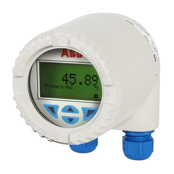
ABB TTF300 Operating Instruction
Field-mount temperature transmitter for all communications protocols, redundancy thanks to two inputs
Hide thumbs
Also See for TTF300:
- Commissioning instructions (364 pages) ,
- Operating instruction (92 pages) ,
- Manual (48 pages)
Table of Contents
Advertisement
Quick Links
—
A B B M E A S U R E M E N T & A N A L Y T I C S | O P E R A T I N G I N S T R U C T I O N
TTF300
Field-mount temperature transmitter
—
Introduction
TTF300
The TTF300 is available with the HART,
PROFIBUS PA and FOUNDATION Fieldbus
communication protocols.
The TTF300 has global approvals for explosion
protection up to Zone 0.
Safety-relevant applications up to SIL 3
(redundant) are supported in accordance with
IEC 61508.
The TTF300 is approved for custody transfer
measurements by MID certificate in accordance
with the Measuring Instruments Directive
2014/32/EU.
Temperature transmitter for all
communications protocols.
Redundancy thanks to two inputs.
Measurement made easy
Additional Information
Additional documentation on TTF300 is available for
download free of charge at
www.abb.com/temperature.
Alternatively simply scan this code:
Advertisement
Table of Contents

Related Manuals for ABB TTF300


Summary of Contents for ABB TTF300
- Page 1 Redundancy thanks to two inputs. Measurement made easy — Introduction Additional Information TTF300 The TTF300 is available with the HART, Additional documentation on TTF300 is available for PROFIBUS PA and FOUNDATION Fieldbus download free of charge at communication protocols. www.abb.com/temperature.
-
Page 2: Table Of Contents
TTF300 FIELD-MOUNT TEMPERATURE TRANSMITTER | OI/TTF300-EN REV. G Table of contents Change from one to two columns Product identification ..........22 Safety ................4 Name plate ................22 General information and instructions ........4 ... - Page 3 TTF300 FIELD-MOUNT TEMPERATURE TRANSMITTER | OI/TTF300-EN REV. G Diagnosis / error messages ........64 Commissioning ............39 Diagnostic information ............64 General ..................39 Monitoring of operating data ......... 64 Checks prior to commissioning .......... 39 ...
-
Page 4: Safety
TTF300 FIELD-MOUNT TEMPERATURE TRANSMITTER | OI/TTF300-EN REV. G 1 Safety Warnings General information and instructions The warnings in these instructions are structured as follows: These instructions are an important part of the product and must be retained for future reference. -
Page 5: Intended Use
/ or theft of data or information. the SIL Safety Manual should be observed. ABB Automation Products GmbH and its affiliates are not liable for damages and / or losses related to such security breaches, any unauthorized access, interference, intrusion, leakage and / Improper use or theft of data or information. -
Page 6: Use In Potentially Explosive Atmospheres In Accordance With Atex And Iecex
TTF300 FIELD-MOUNT TEMPERATURE TRANSMITTER | OI/TTF300-EN REV. G Change from two to one column 2 Use in potentially explosive atmospheres in accordance with ATEX and IECEx hange from one to two columns Ex marking ATEX dust explosion protection and intrinsic safety Approved for zone 21, 22 and Zone 0, 1 and 2. -
Page 7: Lcd Indicator
TTF300 FIELD-MOUNT TEMPERATURE TRANSMITTER | OI/TTF300-EN REV. G IECEx intrinsic safety LCD indicator Approved for use in Zone 0, 1, and 2. ATEX intrinsic safety The device fulfills the requirements of Directive 2014/34/EU in Model TTF300-H1H case of corresponding purchase orders and is approved for use IECEx certificate of conformity IECEx PTB 09.0014X... -
Page 8: Temperature Data
TTF300 FIELD-MOUNT TEMPERATURE TRANSMITTER | OI/TTF300-EN REV. G … 2 Use in potentially explosive atmospheres in accordance with ATEX and IECEx Temperature data Electrical data Transmitter Transmitter ATEX / IECEx intrinsic safety, ATEX non-sparking Intrinsic safety type of protection Ex ia IIC (Part 1) -
Page 9: Lcd Indicator
In this case, the electric data of the transmitter for the intrinsic safety type of protection Ex ia IIC (Part 1) for TTF300-E1H and TTF300-H1H, Ex ia IIC (Part 2) as well Ex ia IIC (Part 3) should be complied with. -
Page 10: Installation Instructions
TTF300 FIELD-MOUNT TEMPERATURE TRANSMITTER | OI/TTF300-EN REV. G … 2 Use in potentially explosive atmospheres in accordance with ATEX and IECEx Installation instructions ATEX / IECEx Installation instructions for cable glands The sealing rings of the cable glands harden at low The installation, commissioning, maintenance and repair of temperatures. -
Page 11: Electrical Connections
TTF300 FIELD-MOUNT TEMPERATURE TRANSMITTER | OI/TTF300-EN REV. G Maintenance Intrinsic safety installation check Check the cable glands during each maintenance session. If the If transmitters are operated in an intrinsically safe circuit, proof cable is slack, retighten the cap(s) of the cable glands. - Page 12 (observe the warnings on the device). Risk of explosion! When using the device in areas which require the ‘Ga’ equipment protection level - EPL (Zone 0), the TTF300 types should be installed with aluminum housings to protect against mechanical impact loads or friction.
- Page 13 TTF300 FIELD-MOUNT TEMPERATURE TRANSMITTER | OI/TTF300-EN REV. G ATEX – Zone 1 (20) ATEX – Zone 2 Marking: II 2 G (1D) Ex [ia IIIC Da] ib IIC T6 Gb Designation: II 3 G Ex nA IIC T1-T6 Gc Zone 20 or 21...
- Page 14 TTF300 FIELD-MOUNT TEMPERATURE TRANSMITTER | OI/TTF300-EN REV. G … 2 Use in potentially explosive atmospheres in accordance with ATEX and IECEx … Installation instructions Dust explosion protection – Zone 21 Dust explosion protection – Zone 0/21 Marking: Housing design: ATEX II 2D Ex tb IIIC T135°C Db II 2D Ex tb IIIC T135°C Db...
- Page 15 TTF300 FIELD-MOUNT TEMPERATURE TRANSMITTER | OI/TTF300-EN REV. G Flameproof (enclosure) – Zone 1 The transmitter must be connected using suitable cable and cable entries or pipeline systems that satisfy the requirements Housing design: ATEX II 2G Ex db IIC T6/T4 Gb of EN 60079-1 and for which a separate examination certificate exists.
-
Page 16: Commissioning
Alternatively, an Ex modem can be connected to the circuit • The device may only be repaired by the ABB Service outside the potentially explosive atmosphere. Department. •... -
Page 17: Use In Potentially Explosive Atmospheres In Accordance With Fm And Csa
TTF300 FIELD-MOUNT TEMPERATURE TRANSMITTER | OI/TTF300-EN REV. G Change from two to one column 3 Use in potentially explosive atmospheres in accordance with FM and CSA Change from one to two columns Note CSA Intrinsically Safe • Further information on the approval of devices for use in... -
Page 18: Lcd Indicator
TTF300 FIELD-MOUNT TEMPERATURE TRANSMITTER | OI/TTF300-EN REV. G … 3 Use in potentially explosive atmospheres in accordance with FM and CSA … Ex marking Installation instructions LCD indicator FM / CSA FM Intrinsically Safe The installation, commissioning, maintenance and repair of devices in areas with explosion hazard must only be carried out by appropriately trained personnel. -
Page 19: Commissioning
TTF300 FIELD-MOUNT TEMPERATURE TRANSMITTER | OI/TTF300-EN REV. G Commissioning Proof of intrinsic safety is said to have been provided if the The commissioning and parameterization of the device may also following conditions are fulfilled when a comparison is carried be carried out in potentially explosive atmospheres using a... -
Page 20: Repair
Explosion hazard Explosion hazard due to improper repair of the device. Faulty devices must not be repaired by the operator. • The device may only be repaired by the ABB Service Department. • Repairs on flameproof joints are not permitted. -
Page 21: Design And Function
Sensor Redundancy In the HART® transmitter, an FSK signal is superimposed on the To enhance system availability, the TTF300 has two sensor 4 to 20 mA output signal in accordance with the HART standard inputs. to facilitate bidirectional communication. -
Page 22: Sensor Error Adjustment In Accordance With Callendar-Van Dusen
TTF300 FIELD-MOUNT TEMPERATURE TRANSMITTER | OI/TTF300-EN REV. G … 4 Design and function 5 Product identification … Input functionality Name plate If drift monitoring is used for the same types of sensor Note (2 × Pt100 or 2 × thermocouple), the mean value calculated from The name plates displayed are examples. -
Page 23: Explosion Protection Marking For Devices With One Type Of Protection
TTF300 FIELD-MOUNT TEMPERATURE TRANSMITTER | OI/TTF300-EN REV. G Explosion protection marking for devices with a combination of explosion protection types Coding of the type of protection of the device in accordance with order information can also refer to a combination of different explosion approvals for various types of protection. -
Page 24: Transport And Storage
TTF300 FIELD-MOUNT TEMPERATURE TRANSMITTER | OI/TTF300-EN REV. G … 5 Product identification 6 Transport and storage … Name plate Inspection Devices with combined types of protection may only be Check the devices immediately after unpacking for possible operated in one of the possible types of protection. -
Page 25: Installation
TTF300 FIELD-MOUNT TEMPERATURE TRANSMITTER | OI/TTF300-EN REV. G 7 Installation Mounting Note When using the device in potentially explosive atmospheres, note the additional data in Use in potentially explosive atmospheres in accordance with ATEX and IECEx on page 6 and... -
Page 26: Opening And Closing The Housing
TTF300 FIELD-MOUNT TEMPERATURE TRANSMITTER | OI/TTF300-EN REV. G … 7 Installation Rotating the LCD indicator Opening and closing the housing DANGER Danger of explosion if the device is operated with the transmitter housing or terminal box open! While using the device in potentially explosive atmospheres... -
Page 27: Electrical Connections
TTF300 FIELD-MOUNT TEMPERATURE TRANSMITTER | OI/TTF300-EN REV. G 8 Electrical connections Safety instructions Protection of the transmitter from damage caused by DANGER highly energetic electrical interferences Improper installation and commissioning of the device The transmitter has no switch-off elements. Therefore, carries a risk of explosion. -
Page 28: Conductor Material
TTF300 FIELD-MOUNT TEMPERATURE TRANSMITTER | OI/TTF300-EN REV. G … 8 Electrical connections Shielding of the sensor connecting cable … Safety instructions To ensure the system benefits from optimum electromagnetic Suited protective measures interference immunity, the individual system components, and The following items should be observed to protect the the connection cables in particular, need to be shielded. -
Page 29: Examples Of Shielding / Grounding
TTF300 FIELD-MOUNT TEMPERATURE TRANSMITTER | OI/TTF300-EN REV. G Examples of shielding / grounding Insulated sensor measuring inset (thermocouple, mV, RTD, ohms), transmitter housing grounded The shielding of the sensor connection cable is grounded via the grounded transmitter housing. This shielding is insulated from the sensor. - Page 30 TTF300 FIELD-MOUNT TEMPERATURE TRANSMITTER | OI/TTF300-EN REV. G … 8 Electrical connections … Shielding of the sensor connecting cable Insulated sensor measuring inset (thermocouple, mV, RTD, ohms), transmitter housing not grounded The shielding of the power supply cable and the shielding of the sensor connection cable are connected to one another via the transmitter housing.
-
Page 31: Pin Assignment
TTF300 FIELD-MOUNT TEMPERATURE TRANSMITTER | OI/TTF300-EN REV. G Pin assignment Resistance thermometers (RTD) / resistors (potentiometer) A Potentiometer, four-wire circuit I Sensor 1 B Potentiometer, three-wire circuit J Sensor 2* C Potentiometer, two-wire circuit K 4 to 20 mA HART®, PROFIBUS PA®, FOUNDATION Fieldbus®... - Page 32 TTF300 FIELD-MOUNT TEMPERATURE TRANSMITTER | OI/TTF300-EN REV. G … 8 Electrical connections … Pin assignment Thermocouples / voltages and resistance thermometer (RTD) / thermocouple combinations A 2 x voltage measurement* H Sensor 1 B 1 x voltage measurement I Sensor 2* C 2 x thermocouple* J 4 to 20 mA HART®, PROFIBUS PA®, FOUNDATION Fieldbus®...
-
Page 33: Terminal For Sensor Connection Cable
TTF300 FIELD-MOUNT TEMPERATURE TRANSMITTER | OI/TTF300-EN REV. G Terminal for sensor connection cable Electrical data for inputs and outputs Input - resistance thermometer / resistances DANGER Resistance thermometer Danger of explosion if the device is operated with the • Pt100 in accordance with IEC 60751, JIS C1604, MIL-T-24388 transmitter housing or terminal box open! •... -
Page 34: Input - Thermocouples / Voltages
TTF300 FIELD-MOUNT TEMPERATURE TRANSMITTER | OI/TTF300-EN REV. G … 8 Electrical connections … Electrical data for inputs and outputs Input - thermocouples / voltages Output – HART® Types B, E, J, K, N, R, S, T in accordance with IEC 60584 •... -
Page 35: Output - Profibus Pa
TTF300 FIELD-MOUNT TEMPERATURE TRANSMITTER | OI/TTF300-EN REV. G Output – PROFIBUS PA® Output – FOUNDATION Fieldbus® Note Note The PROFIBUS PA® protocol is an unsecured protocol, as such The FOUNDATION Fieldbus® protocol is an unsecured protocol, the intended application should be assessed to ensure that as such the intended application should be assessed to ensure these protocols are suitable before implementation. -
Page 36: Power Supply
TTF300 FIELD-MOUNT TEMPERATURE TRANSMITTER | OI/TTF300-EN REV. G … 8 Electrical connections … Electrical data for inputs and outputs Power supply Voltage drop on the signal line When connecting the devices, note the voltage drop on the Two-wire technology, polarity safe; power supply lines = signal signal line. -
Page 37: Power Supply - Profibus / Foundation Fieldbus
TTF300 FIELD-MOUNT TEMPERATURE TRANSMITTER | OI/TTF300-EN REV. G Power supply – PROFIBUS / FOUNDATION Fieldbus Input terminal voltage Non-Ex application: = 9 to 32 V DC Ex-applications with: = 9 to 17 V DC (FISCO) = 9 to 24 V DC (Fieldbus Entity model I.S.) Current consumption: ≤... -
Page 38: Mid Certification
TTF300 FIELD-MOUNT TEMPERATURE TRANSMITTER | OI/TTF300-EN REV. G 9 MID Certification TTF300 with MID certification The temperature transmitter TTF300 is certified by an MID Parts Areas of application, conditions and requirements Certificate in accordance with the Measuring Instruments The temperature transmitter TTF300 with MID certification for Directive 2014/32/EU (MID) and the standard WELMEC 7.2. -
Page 39: Commissioning
TTF300 FIELD-MOUNT TEMPERATURE TRANSMITTER | OI/TTF300-EN REV. G 10 Commissioning General In case of corresponding order the transmitter is ready for The device is listed with the FieldComm Group. operation after mounting and installation of the connections. The parameters are set at the factory. -
Page 40: Profibus® Communication
TTF300 FIELD-MOUNT TEMPERATURE TRANSMITTER | OI/TTF300-EN REV. G … 10 Commissioning … Communication PROFIBUS® Communication FOUNDATION Fieldbus® Communication Note Note The PROFIBUS PA® protocol is an unsecured protocol, as such The FOUNDATION Fieldbus® protocol is an unsecured protocol, the intended application should be assessed to ensure that as such the intended application should be assessed to ensure these protocols are suitable before implementation. -
Page 41: Basic Setup
TTF300 FIELD-MOUNT TEMPERATURE TRANSMITTER | OI/TTF300-EN REV. G Basic Setup Note Transmitter communication and configuration via HART, PROFIBUS PA, and FOUNDATION Fieldbus H1 are described in separate documentation (‘Interface description’). The following configuration types are available for the transmitter: •... -
Page 42: Operation
TTF300 FIELD-MOUNT TEMPERATURE TRANSMITTER | OI/TTF300-EN REV. G 11 Operation Safety instructions Menu navigation If there is a chance that safe operation is no longer possible, take the device out of operation and secure it against unintended startup. Hardware settings... -
Page 43: Hart® Menu Levels
TTF300 FIELD-MOUNT TEMPERATURE TRANSMITTER | OI/TTF300-EN REV. G HART® menu levels Process display Configuration level Device Setup Device Info Display Process Alarm Communication Calibrate Diagnosis Process display The process display shows the current process values. Configuration level The configuration level contains all the parameters required for device commissioning and configuration. The device configuration can be changed on this level. -
Page 44: Process Display
TTF300 FIELD-MOUNT TEMPERATURE TRANSMITTER | OI/TTF300-EN REV. G … 11 Operation Process display Error messages on the HART® LCD display If the event of an error, a message consisting of a symbol or letter (device status) and a number (DIAG NO.) will appear at the 25.7... -
Page 45: Error Messages On The Profibus Pa® And Foundation Fieldbus® Lcd Display
TTF300 FIELD-MOUNT TEMPERATURE TRANSMITTER | OI/TTF300-EN REV. G Switching to the information level Error messages on the PROFIBUS PA® and (PROFIBUS PA and FOUNDATION Fieldbus only) FOUNDATION Fieldbus® LCD display On the information level, the operator menu can be used to... -
Page 46: Switching To The Configuration Level (Parameterization)
TTF300 FIELD-MOUNT TEMPERATURE TRANSMITTER | OI/TTF300-EN REV. G … 11 Operation Switching to the configuration level (parameterization) Numerical entry When a numerical entry is made, a value is set by entering the The device parameters can be displayed and changed on the individual decimal positions. - Page 47 TTF300 FIELD-MOUNT TEMPERATURE TRANSMITTER | OI/TTF300-EN REV. G Alphanumeric entry When an alphanumeric entry is made, a value is set by entering the individual decimal positions. Menu name Parameter name Currently set value Next Edit 1. Select the parameters you want to set in the menu.
-
Page 48: Hart® Parameter Overview
TTF300 FIELD-MOUNT TEMPERATURE TRANSMITTER | OI/TTF300-EN REV. G … 11 Operation HART® Parameter Overview Note This overview of parameters shows all the menus and parameters available on the device. Depending on the version and configuration of the device, not all of the menus and parameters may be visible in it. - Page 49 TTF300 FIELD-MOUNT TEMPERATURE TRANSMITTER | OI/TTF300-EN REV. G Calibrate Measured range Apply Lower Range Apply Upper Range Analog Out Trim 4 mA Trim 20 mA Diagnosis Looptest Device status Temp. of Electronics Sensor 1 process data Sensor 2 process data...
-
Page 50: Parameter Description Hart
TTF300 FIELD-MOUNT TEMPERATURE TRANSMITTER | OI/TTF300-EN REV. G … 11 Operation Parameter description HART® Menu: Device Setup Menu / parameter Description … / Device Setup Write protection Activates write protection for the entire device • Yes: locked Entry combination: ≠ 0110 •... - Page 51 TTF300 FIELD-MOUNT TEMPERATURE TRANSMITTER | OI/TTF300-EN REV. G Menu / parameter Description … / Device Setup / Input Sensor 1 … / Device Setup / Input Sensor 2 Sensor Type Selection of the sensor type (continued): • –125 ... 125 mV: Linear voltage measurement -125 to 125 mV •...
- Page 52 TTF300 FIELD-MOUNT TEMPERATURE TRANSMITTER | OI/TTF300-EN REV. G … 11 Operation … Parameter description HART® Menu / parameter Description R-Connection Sensor connection type relevant for all Pt, Ni, Cu resistance thermometers • two-wire: Sensor connection type in two-wire technology •...
-
Page 53: Menu: Device Info
TTF300 FIELD-MOUNT TEMPERATURE TRANSMITTER | OI/TTF300-EN REV. G Menu: Device Info Menu / parameter Description … / Device Info Device Type Displays device type. Serial Number Displays device serial number. Software Version Displays device software version. Hardware Version Displays device hardware version. -
Page 54: Menu: Process Alarm
TTF300 FIELD-MOUNT TEMPERATURE TRANSMITTER | OI/TTF300-EN REV. G … 11 Operation … Parameter description HART® Menu: Process Alarm Menu / parameter Description … / Process Alarm Fault signaling • Underrange: in the event of an error, the current, for example 3.6 mA, is output •... -
Page 55: Menu: Diagnosis
TTF300 FIELD-MOUNT TEMPERATURE TRANSMITTER | OI/TTF300-EN REV. G Menu: Diagnosis Menu / parameter Description … / Diagnosis Looptest Simulates the current output signal Value range: 0 to 23.600 mA Device status Diagnosis notice (maintenance required, error, etc.) Temp. of Electronics... -
Page 56: Profibus Pa® Und Foundation Fieldbus® Parameter Overview
TTF300 FIELD-MOUNT TEMPERATURE TRANSMITTER | OI/TTF300-EN REV. G … 11 Operation PROFIBUS PA® und FOUNDATION Fieldbus® Parameter overview Note This overview of parameters shows all the menus and parameters available on the device. Depending on the version and configuration of the device, not all of the menus and parameters may be visible in it. - Page 57 TTF300 FIELD-MOUNT TEMPERATURE TRANSMITTER | OI/TTF300-EN REV. G Display Language Contrast Operator Page 1 Line 1 Operator Page 2 Line 1 Line 2 Calibrate Reset Device Reset with Defaults PROFIBUS PA only...
-
Page 58: Parameter Description Profibus Pa® And Foundation Fieldbus
TTF300 FIELD-MOUNT TEMPERATURE TRANSMITTER | OI/TTF300-EN REV. G … 11 Operation Parameter description PROFIBUS PA® and FOUNDATION Fieldbus® Menu: Device Setup Menu / parameter Description … / Device Setup Sensor 1 / Sensor 2 Selects sensor type: • Pt100 (IEC751): Resistance thermometer Pt100 (IEC751) •... - Page 59 TTF300 FIELD-MOUNT TEMPERATURE TRANSMITTER | OI/TTF300-EN REV. G Menu / parameter Description (continuation) Sensor 1 / Sensor 2 Selection of the sensor type (continued): • Ni50 (DIN43760): Resistance thermometer Ni50 (DIN43716) • Ni100 (DIN43760): Resistance thermometer Ni100 (DIN43716) • Ni120 (DIN43760): Resistance thermometer Ni120 (DIN43716) •...
-
Page 60: Menu: Device Info
TTF300 FIELD-MOUNT TEMPERATURE TRANSMITTER | OI/TTF300-EN REV. G … 11 Operation … Parameter description PROFIBUS PA® and FOUNDATION Fieldbus® Menu: Device Info Menu / parameter Description … / Device Info Device ID Displays device ID Serial Number Displays serial number... -
Page 61: Menu: Service Menu
TTF300 FIELD-MOUNT TEMPERATURE TRANSMITTER | OI/TTF300-EN REV. G Menu: Service Menu Menu / parameter Description … / Service Menu Device temperature Select the ‘Device temperature’ submenu. Sensor 1 Select the ‘Sensor 1’ submenu. Sensor 2 Select the ‘Sensor 2’ submenu. -
Page 62: Menu: Display
TTF300 FIELD-MOUNT TEMPERATURE TRANSMITTER | OI/TTF300-EN REV. G … 11 Operation … Parameter description PROFIBUS PA® and FOUNDATION Fieldbus® Menu: Display Menu / parameter Description … / Display Language Selects the menu language • German • English Contrast Sets the display contrast... -
Page 63: Factory Settings
TTF300 FIELD-MOUNT TEMPERATURE TRANSMITTER | OI/TTF300-EN REV. G Factory settings Firmware settings The transmitter is configured at the factory. The table below contains the relevant parameter values. Menu Designation Parameter Factory setting Device Setup Write protection – Input Sensor 1... -
Page 64: Diagnosis / Error Messages
TTF300 FIELD-MOUNT TEMPERATURE TRANSMITTER | OI/TTF300-EN REV. G 12 Diagnosis / error messages Diagnostic information Monitoring of operating data The transmitter saves the highest and lowest values for the electronic unit temperature as well as measured values from sensor 1 and sensor 2 in the non-volatile memory (‘Drag Indicator’). -
Page 65: Calling Up The Error Description
TTF300 FIELD-MOUNT TEMPERATURE TRANSMITTER | OI/TTF300-EN REV. G Calling up the error description For PROFIBUS PA and FOUNDATION Fieldbus transmitters only! Additional details about the error that has occurred can be called up on the information level. Process display Electronics 1. -
Page 66: Possible Error Messages - Hart
TTF300 FIELD-MOUNT TEMPERATURE TRANSMITTER | OI/TTF300-EN REV. G … 12 Diagnosis / error messages Possible error messages – HART® Range Displays the Displays the Cause Remedy device DIAG. NO. status Electronics Device defective Replace the device Electronics Ambient temperature overshot / undershot Check environment;... - Page 67 Lower limit value: alarm Operating conditions Limit HIGH Upper limit value: warning Operating conditions Limit LOW Lower limit value: warning Note If the remedial measures listed for the error message do not improve the status of the device, please consult ABB Service.
-
Page 68: Possible Error Messages - Profibus Pa® And Foundation Fieldbus
Sensor 2 redundancy, wire break Maintenance required Rectify break at sensor 2 or replace sensor 2 Note If the remedial measures listed for the error message do not improve the status of the device, please consult ABB Service. Change from one to two columns... -
Page 69: Maintenance
All devices delivered to ABB must be free from any hazardous When using the device in potentially explosive atmospheres, materials (acids, alkalis, solvents, etc.). observe the notice on cleaning in Protection against electrostatic discharges on page 16. -
Page 70: Recycling And Disposal
16 Specification Note Note Products that are marked with the adjacent symbol The device data sheet is available in the ABB download area at may not be disposed of as unsorted municipal waste www.abb.com/temperature. (domestic waste). They should be disposed of through separate collection of electric and electronic devices. -
Page 71: Appendix
TTF300 FIELD-MOUNT TEMPERATURE TRANSMITTER | OI/TTF300-EN REV. G 18 Appendix Return form Statement on the contamination of devices and components Repair and/or maintenance work will only be performed on devices and components if a statement form has been completed and submitted. - Page 72 We reserve the right to make technical changes or modify the contents of this document without prior notice. With regard to purchase orders, the agreed particulars shall prevail. ABB does not accept any responsibility whatsoever for potential errors or possible lack of information in this document.