Mitsubishi Electric MELSEC iQ-F Series Quick Start Manual
Safety extension module
Hide thumbs
Also See for MELSEC iQ-F Series:
- User manual (282 pages) ,
- Handbook (132 pages) ,
- Programming manual (128 pages)

Related Manuals for Mitsubishi Electric MELSEC iQ-F Series


Summary of Contents for Mitsubishi Electric MELSEC iQ-F Series
- Page 1 FACTORY AUTOMATION Programmable Controller MELSEC iQ-F Series Quick Start Guide (Safety Extension Module)
-
Page 2: Introduction
Mitsubishi Electric is not liable for damages that could have been prevented by compliance with any applicable safety standard, regulation or law. -
Page 3: Table Of Contents
CONTENTS INTRODUCTION ................................2 RELEVANT MANUALS ..............................4 RECOMMENDED POINTS 1 PREPARATION 1.1 Before Connecting Safety Devices ..........................7 1.2 Safety Application Example .............................8 1.2.1 Safety application example described in this manual ..................8 1.2.2 Connection example of safety devices ......................9 1.2.3 Operation flow ..............................10 1.3 Required Products ..............................11 2 EXAMINATION OF SAFETY CONTROL CIRCUITS 2.1 Operation of Program 7 ............................12... -
Page 4: Relevant Manuals
2.2 Part Names of the Safety Input Expansion Module (FX5-SF-8DI4) ..............47 2.3 LED indications ..............................48 3 When MELSEC iQ-F Series Safety Extension Module Configuration Guide Does Not Start ........49 4 Buffer Memory ................................51 5 Examples of Sequence Programs for Checking the Safety Extension Module Status ..........52 6 Safety Components Partner Products ........................54... -
Page 5: Recommended Points
MELSEC iQ-F Series Safety Extension Module Configuration Guide Printing of a wiring diagram Built-in program : MELSEC iQ-F Series Safety Extension Module Configuration Guide can be downloaded from the Mitsubishi Electric FA site. https://www.mitsubishielectric.com/fa/ref/ref.html?kisyu=plcf&&software=iqfsafety_cfgguide... - Page 6 RECOMMENDED POINTS Point Downtime reduction improves operating rate. Error details and corrective actions of the safety extension module can be checked using the module diagnostic function of GX Works3, helping early recovery from an error. Error "Module Diagnostics" window Information such as safety device settings and input/output status can be checked in the buffer memory, reducing the recovery time.
-
Page 7: Preparation
1 PREPARATION Before Connecting Safety Application Required Products Safety Devices Example 1.1 Before Connecting Safety Devices Preparing required Examining safety Selecting a built- products control circuits in program Rotary switch Setting the safety Wiring the safety Applying the safety main module main module main module settings Emergency stop... -
Page 8: Safety Application Example
1 PREPARATION Before Connecting Safety Application Required Products Safety Devices Example 1.2 Safety Application Example This manual describes the settings and wiring of the safety main module (FX5-SF-MU4T5), the settings of the FX5U CPU module, and the safety devices, such as emergency stop pushbuttons and safety light curtains, using the following safety application example. -
Page 9: Connection Example Of Safety Devices
1 PREPARATION Before Connecting Safety Application Required Products Safety Devices Example 1.2.2 Connection example of safety devices Reset Reset Start switch Safety light curtain Emergency stop switch 1 switch 2 pushbutton Partial stop Entire stop FX5U CPU module Safety main module (FX5-SF-MU4T5) "program 7"... -
Page 10: Operation Flow
1 PREPARATION Before Connecting Safety Application Required Products Safety Devices Example 1.2.3 Operation flow The following shows the operation flow of the safety application. Power ON External device monitoring (EDM) Whether the Safety contactor NC safety contactor External device contact: OFF is welded or not monitoring (EDM) (The safety contactors... -
Page 11: Required Products
Pushbutton switch (Supporting mirror contact (automatic return type) × 2 × 4 (manufactured by Mitsubishi Electric: SD-Q11 This safety device is described as "safety contactor" in this manual. GX Works3 *1: Mirror contact is a mechanism that detects welding of a main contact. -
Page 12: Examination Of Safety Control Circuits
2 EXAMINATION OF SAFETY CONTROL CIRCUITS Operation of Logic Diagram of Program 7 Program 7 There are nine built-in programs in the safety main module (FX5-SF-MU4T5). The program 7 is applied to the safety application example ( P. 8 ) described in this manual. This section describes the operation of the program 7. -
Page 13: Logic Diagram Of Program 7
2 EXAMINATION OF SAFETY CONTROL CIRCUITS Operation of Logic Diagram of Program 7 Program 7 2.2 Logic Diagram of Program 7 NC input Safety output Dual wiring NC input Safety output (NC/NC) NC input Safety output Dual wiring NC input Safety output (NC/NC) NC input and NO input operations... -
Page 14: Selection Of A Built-In Program
MELSEC iQ-F Series Safety Extension Module Configuration Guide can be downloaded from the following URL. https://www.mitsubishielectric.com/fa/ref/ref.html?kisyu=plcf&&software=iqfsafety_cfgguide Step 2 . Installation Extract the downloaded MELSEC iQ-F Series Safety Extension Module Configuration Guide, and store it to a local folder. (Save destination example: C:\) Step 3 . -
Page 15: Module Selection
In this manual, " " is used. For details on the window configuration, refer to the following. Appendix 6 How to Use MELSEC iQ-F Series Safety Extension Module Configuration Guide in the MELSEC iQ-F MELSEC iQ-F FX5 User's Manual (Safety Control). -
Page 16: Input Device Selection
3 SELECTION OF A BUILT-IN PROGRAM Input Device Output Device General Input Printing of Module Printing of Wiring Installation Module Selection Selection Selection Settings Configuration Diagram 3.3 Input Device Selection After selecting the safety main module ( P. 15 ), select input devices. For the selectable input devices, refer to Connectable devices and ladder symbols in the MELSEC iQ-F FX5 User's Manual (Safety... - Page 17 3 SELECTION OF A BUILT-IN PROGRAM Input Device Output Device General Input Printing of Module Printing of Wiring Installation Module Selection Selection Selection Settings Configuration Diagram Selecting a safety light curtain The connection configuration of the emergency Select "Electro-sensitive protective stop pushbutton and safety light curtain to the equipment (ESPE)".
-
Page 18: Output Device Selection
3 SELECTION OF A BUILT-IN PROGRAM Input Device Output Device General Input Printing of Module Printing of Wiring Installation Module Selection Selection Selection Settings Configuration Diagram 3.4 Output Device Selection Select output devices. Select the following in sequence. Click Output Devices Mod 1 - Q0 - MU Mod 1 - Q1 - MU Mod 1 - Q2 - MU... -
Page 19: General Input Settings
3 SELECTION OF A BUILT-IN PROGRAM Input Device Output Device General Input Printing of Module Printing of Wiring Installation Module Selection Selection Selection Settings Configuration Diagram 3.5 General Input Settings Set the following to execute the external device monitoring (EDM) and the reset switch status check in the operation flow ( P. -
Page 20: Printing Of Module Configuration
3 SELECTION OF A BUILT-IN PROGRAM Input Device Output Device General Input Printing of Module Printing of Wiring Installation Module Selection Selection Selection Settings Configuration Diagram 3.6 Printing of Module Configuration Display the module configuration of the selected safety main module, input devices, and output devices on the configuration window, and print it. -
Page 21: Printing Of Wiring Diagram
3 SELECTION OF A BUILT-IN PROGRAM Output Device Printing of Module Printing of Wiring Installation Module Selection Input Device Selection General Input Settings Selection Configuration Diagram 3.7 Printing of Wiring Diagram Display the wiring diagram of the selected safety main module, input devices, output devices, and general input settings on the wiring window, and print them. -
Page 22: Safety Main Module Settings
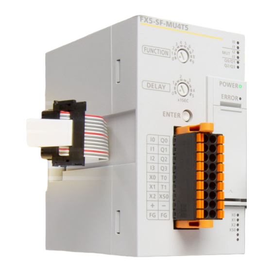
4 SAFETY MAIN MODULE SETTINGS 4 SAFETY MAIN MODULE SETTINGS Part Names Set the following for the safety application example ( ) in this manual. Rotary switch Initial value Setting range Setting value FUNCTION 0 to 9 DELAY 0.0 s 0.0 s, 0.5 s, 1.0 s, 1.5 s, 2.0 s, 2.5 s, 3.0 s, 3.5 s, 4.0 s, 5.0 s 0.0 s Rotary switch... -
Page 23: Safety Main Module Wiring
5 SAFETY MAIN MODULE WIRING Terminal Safety Contactor Power Supply Input Wiring Arrangement Wiring Wiring Wire the safety main module and the safety devices based on the wiring diagram created using MELSEC iQ-F Series Safety Extension Module Configuration Guide. The following shows the wiring diagram of Input wiring (Emergency stop pushbutton) Input wiring... -
Page 24: Input Wiring
5 SAFETY MAIN MODULE WIRING Terminal Safety Contactor Power Supply Input Wiring Arrangement Wiring Wiring 5.2 Input Wiring Wiring between the emergency stop pushbutton (ES21-SB10G1) and the safety main module The following shows the wiring between the emergency stop pushbutton and the safety main module. 24 VDC Backside of the emergency stop... -
Page 25: Safety Contactor Wiring
5 SAFETY MAIN MODULE WIRING Terminal Safety Contactor Power Supply Input Wiring Arrangement Wiring Wiring 5.3 Safety Contactor Wiring Wiring of safety contactors, restart interlocks, and EDM 24 VDC Safety contactor RESET Q0/Q1 Pushbutton switch (automatic return type) Spring clamp terminal block of the safety main module RESET Q3 Pushbutton switch... -
Page 26: Application Of Safety Main Module Settings
6 APPLICATION OF SAFETY MAIN MODULE SETTINGS This section describes how to apply the settings of the FUNCTION and DELAY rotary switches ( P. 22 ) to the safety main module (FX-SF-MU4T5). Point Wire safety devices to the safety main module before applying the settings. ( P. -
Page 27: Cpu Module Settings
7 CPU MODULE SETTINGS Communication Writing Data to the Parameter Settings Settings Programmable Controller This section describes how to add a safety extension module to the module configuration using GX Works3. 7.1 Parameter Settings Using GX Works3 (Required Settings) Drag and drop a safety main module (FX5-SF-MU4T5), and double-click the added FX5-SF-MU4T5. Drag and drop Double-click Click the [OK] button. -
Page 28: Communication Settings Using Gx Works3
7 CPU MODULE SETTINGS Communication Writing Data to the Parameter Settings Settings Programmable Controller Directly connect the Ethernet ports with a cable as shown below. Perform a communication test before writing data to the programmable controller. FX5U CPU FX5-SF-MU4T5 Ethernet 7.2 Communication Settings Using GX Works3 Select [Online] [Current Connection Destination]. - Page 29 7 CPU MODULE SETTINGS Communication Writing Data to the Parameter Settings Settings Programmable Controller Specify the Ethernet adapter of the personal computer that is directly connected to the CPU module. When "Not Specified" is set, select an adapter to be used from the drop-down list. After the adapter is selected, click the button.
-
Page 30: Writing Data To The Programmable Controller
7 CPU MODULE SETTINGS Communication Writing Data to the Parameter Settings Settings Programmable Controller 7.3 Writing Data to the Programmable Controller Convert the program and write data to the programmable controller. Select [Convert] [Rebuild All]. Click the OK button. The program is transferred to the programmable controller. Select [Online] [Write to PLC]. - Page 31 7 CPU MODULE SETTINGS Communication Writing Data to the Parameter Settings Settings Programmable Controller Click the [Parameter + Program] button, and click the button. Execute Click the OK button. When the data is written to the programmable controller, power OFF the FX5U CPU module and the safety main module, and then power them ON simultaneously (within two seconds).
-
Page 32: Operation Check Of Safety Circuits
8 OPERATION CHECK OF SAFETY CIRCUITS Installation of Safety Operation Check Light Curtain 8.1 Installation of Safety Light Curtain Install the safety light curtain. For details, refer to the following. deTec4 Safety light curtain OPERATING INSTRUCTIONS 8.2 Operation Check Check the following operations after the packaging machine in the connection example of the safety devices P. - Page 33 8 OPERATION CHECK OF SAFETY CIRCUITS Installation of Safety Operation Check Light Curtain Partial stop Check that some safety contactors turn OFF when the safety light curtain detects a person. Step 1 . Inserting a test rod into the safety light curtain Insert the test rod into the safety light curtain.
-
Page 34: Troubleshooting
9 TROUBLESHOOTING Checking the LED Checking the LED Checking the LED Checking the Error Checking the Error Checking the Error Checking Procedure Checking Procedure Checking Procedure Status Status Status Code Code Code 9.1 Checking Procedure P. 35 Checking the LED status Check the error details with LEDs of the safety main module (FX5-SF-MU4T5) and the FX5U CPU module. -
Page 35: Checking The Led Status
9 TROUBLESHOOTING Checking Procedure Checking the LED Checking the Error Status Code 9.2 Checking the LED Status Checking the LED status is the primary diagnostics without using GX Works3. It narrows down a cause of an error. The following table lists the LEDs of the safety main module (FX5-SF-MU4T5) and the descriptions of each status. For the corrective actions, refer to Section 10.4 List of Error Codes in the MELSEC iQ-F FX5 User's Manual (Safety Control). -
Page 36: Checking The Error Code
9 TROUBLESHOOTING Checking the LED Checking the Error Checking Procedure Status Code 9.3 Checking the Error Code 9.3.1 Module diagnostics Check an error occurred in the module and error history, and identify a cause using GX Works3. The detailed information, such as error causes and corrective actions, obtained from GX Works3 is more helpful than those obtained from LEDs. -
Page 37: Lists Of Error Codes
ON. If the LED does not turn ON, reset the power of the whole system. If the POWER LED of the safety extension module does not turn ON, there is a possibility that the module is malfunctioning. Please contact your local Mitsubishi Electric sales office or representative. 3053H Number of... - Page 38 9 TROUBLESHOOTING Checking the LED Checking the Error Checking Procedure Status Code PU module The following table lists the CPU module error codes when an error occurs in the safety main module. CPU module Safety main module Description and Error code Error code Error Corrective action...
-
Page 39: Appendices
Example 1 Safety Application Examples of Built-In Programs 1.1 Template Files in MELSEC iQ-F Series Safety Extension Module Configuration Guide Template files which correspond to the programs 1 to 9 of the safety main module is included in MELSEC iQ-F Series Safety Extension Module Configuration Guide. -
Page 40: Safety Application Example
Inputs Configuration Guide Example 1.2 Safety Application Example This section describes the safety application examples of the nine different template files in MELSEC iQ-F Series Safety Extension Module Configuration Guide. Program 1: OR control (1) Case example When both the pressure sensitive mat and safety light curtain are turned OFF, all the safety outputs turn OFF. - Page 41 APPENDICES Safety Application Increasing Safety Safety Extension Module Sequence Program Buffer Memory Partner Products Example Inputs Configuration Guide Example Program 3: Muting control Case example When the muting sensor input is turned ON, the safety light curtain is temporarily disabled. Safety output Safety output Safety light curtain...
- Page 42 APPENDICES Safety Application Increasing Safety Safety Extension Module Sequence Program Buffer Memory Partner Products Example Inputs Configuration Guide Example Program 5: Two-hand control (2) Case example When both the two-hand switches and safety light curtain are turned ON, all the safety outputs turn ON. Safety output Safety output Two-hand control switches...
- Page 43 APPENDICES Safety Application Increasing Safety Safety Extension Module Sequence Program Buffer Memory Partner Products Example Inputs Configuration Guide Example Program 8: Independent control Case example When the safety light curtains are turned OFF, the safety outputs turn OFF. Each safety light curtain independently controls the safety output status.
-
Page 44: Increasing Safety Inputs
The following describes the procedure for setting the safety input expansion modules in the program 7 P. 15 ) using MELSEC iQ-F Series Safety Extension Module Configuration Guide. Procedure for adding the safety input extension modules Click "8DI". - Page 45 APPENDICES Safety Application Increasing Safety Safety Extension Module Sequence Program Buffer Memory Partner Products Example Inputs Configuration Guide Example Set the following program, as an example, using of "8DI". 1st 8DI INPUT A rotary switch INPUT B rotary switch 2nd 8DI INPUT A rotary switch INPUT B rotary switch Check that the "&"...
- Page 46 APPENDICES Safety Application Increasing Safety Safety Extension Module Sequence Program Buffer Memory Partner Products Example Inputs Configuration Guide Example Entire logics The following show the entire logics using inputs 1) to 10) and outputs Q0 to Q3. Safety output & Safety output &...
-
Page 47: Part Names Of The Safety Input Expansion Module (Fx5-Sf-8Di4)
APPENDICES Safety Application Increasing Safety Safety Extension Module Sequence Program Buffer Memory Partner Products Example Inputs Configuration Guide Example 2.2 Part Names of the Safety Input Expansion Module (FX5-SF-8DI4) INPUT A rotary switch Sets a built-in program. INPUT B rotary switch Sets a built-in program. -
Page 48: Led Indications
APPENDICES Safety Application Increasing Safety Safety Extension Module Sequence Program Buffer Memory Partner Products Example Inputs Configuration Guide Example 2.3 LED indications Checking the LED status is the primary diagnostics without using GX Works3. It narrows down a cause of an error. The following table lists the LEDs of the safety input expansion module (FX5-SF-8D14) and the descriptions of each status. -
Page 49: When Melsec Iq-F Series Safety Extension Module Configuration Guide Does Not Start
Example 3 When MELSEC iQ-F Series Safety Extension Module Configuration Guide Does Not Start This section describes the corrective actions to be taken when MELSEC iQ-F Series Safety Extension Module Configuration Guide does not operate normally. When MELSEC iQ-F Series Safety Extension Module Configuration Guide does not start normally on Internet Explorer ®... - Page 50 Buffer Memory Partner Products Example Inputs Configuration Guide Example When MELSEC iQ-F Series Safety Extension Module Configuration Guide does not start normally on Internet Explorer ® 11 (2) Perform the following operation. Step 1 . Opening the "Compatibility View Settings" window on Internet Explorer ®...
-
Page 51: Buffer Memory
APPENDICES Safety Application Increasing Safety Safety Extension Module Sequence Program Buffer Memory Partner Products Example Inputs Configuration Guide Example 4 Buffer Memory When an error occurs in the running safety main module (FX5-SF-MU4T5), the error flag turns ON and the error code is stored in "Latest error code"... -
Page 52: Examples Of Sequence Programs For Checking The Safety Extension Module Status
APPENDICES Safety Application Increasing Safety Safety Extension Module Sequence Program Buffer Memory Partner Products Example Inputs Configuration Guide Example 5 Examples of Sequence Programs for Checking the Safety Extension Module Status Example of a sequence program for checking the rotary switch settings of the safety extension modules Buffer memory areas of the safety extension modules Buffer memory name Device... - Page 53 APPENDICES Safety Application Increasing Safety Safety Extension Module Sequence Program Buffer Memory Partner Products Example Inputs Configuration Guide Example Example of a sequence program for checking the safety output status Buffer memory areas of the safety main module (FX5-SF-MU4T5) Buffer memory Device Purpose Status when the device is ON...
-
Page 54: Safety Components Partner Products
APPENDICES Safety Extension Module Sequence Program Safety Application Example Increasing Safety Inputs Buffer Memory Partner Products Configuration Guide Example 6 Safety Components Partner Products State-of-the-art safety system satisfying the international standard Other than efficiency and high-speed performance, machinery safety. The product lineups include advanced functional safety is fundamental requirement of factory products which meet high safety standard of Europe automation. -
Page 55: Warranty
First edition This manual confers no industrial property rights or any rights of any other kind, nor does it confer any patent licenses. Mitsubishi Electric Corporation cannot be held responsible for any problems involving industrial property rights which may occur as a result of using the contents noted in this manual. - Page 56 Mitsubishi Electric Programmable Controller MELSEC iQ-F Series HEAD OFFICE: TOKYO BLDG., 2-7-3, MARUNOUCHI, CHIYODA-KU, TOKYO 100-8310, JAPAN www.MitsubishiElectric.com L(NA)08708ENG-A 2002(MEE)