Mitsubishi Electric MELSEC iQ-F Series Training Manual
Hide thumbs
Also See for MELSEC iQ-F Series:
- User manual (282 pages) ,
- Handbook (132 pages) ,
- Programming manual (128 pages)
Table of Contents
Advertisement
Quick Links
Advertisement
Table of Contents
Troubleshooting

Related Manuals for Mitsubishi Electric MELSEC iQ-F Series


Summary of Contents for Mitsubishi Electric MELSEC iQ-F Series
- Page 1 FX5U Training Manual...
- Page 2 The Definition of a PLC A programmable Logic Controller (PLC) is referred to as a Programmable Controller (PC) or Sequence Controller (SC). A PLC is defined as "an electronic device which controls many types of systems through its I/O ports and incorporates a memory to store programmable instructions." Actual Usages PLCs are broadly used as core components for FA (Factory Automation) and as electronic application products essential for saving labor costs and improving automation.
- Page 3 Mechanism of PLC The PLC is a microcomputer for industrial purposes. Programming tool Programming software GX Works3 Program creating, program transferring, operation monitor, Input devices forced ON/OFF and so on Limit switch Contactor Memory section Memory Lamp Relay contact Toggle switch Solenoid valve (Solenoid valve) Pushbutton switch...
- Page 4 The PLC can be, in effect, considered as an aggregate of relays and timers. Activate input relays Activate the internal sequential Activate output Activate external with external signals circuit with input relay contacts relays loads Power supply COM0 Fuse Output relay Timer M100 K100...
- Page 5 Types of relay and timers As shown below, a PLC incorporates multiple relays, timers and counters with countless N.O. and N.C. contacts. A sequential circuit is formed by connecting the contacts and coils. Also, one advantage of using a PLC is that a lot of storage cases called "data registers" are included. Input Input terminal Input relay: X...
- Page 6 Program processing sequence A CPU module executes operations in series from the start step of the program memory from left to right and from top to bottom (in the order of 1), 2) ... and 17)) in units of a ladder block as shown below.
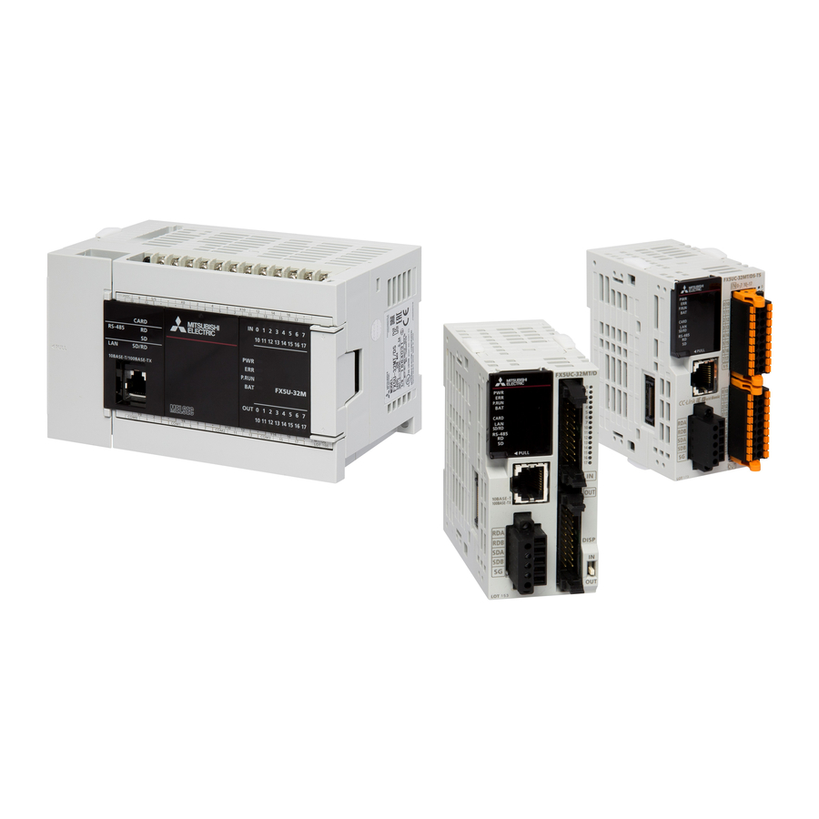
- Page 7 FX5U Hardware Part Names Front panel [10] [11] Name Description DIN rail mounting hooks Hook for mounting the CPU module on a DIN rail of DIN46277 (35 mm wide). Expansion adapter connecting When connecting an expansion adapter, secure it with these hooks. hooks Terminal block cover Cover for protecting the terminal block.
- Page 8 With cover open [10] Name Description Built-in RS-485 communication Terminal block for connection with RS-485-compatible devices terminal block RS-485 terminal resistor selector Switch for switching terminal resistance for built-in RS-485 communication. switch RUN/STOP/RESET switch Switch for operating the CPU module. RUN: Runs the program STOP: Stops the program RESET: Resets the CPU module (hold the switch on the RESET side for approximately 1 second.)
- Page 9 Power, input/output terminal block ■Interpretation of terminal block layout Power supply 24 V DC service [•] Vacant terminal (Do not use) Input terminal terminals power supply S/S 0 V 24 V Output terminals FX5U-32MR/ES connected to COM3 COM0 3 COM1 COM2 COM3 Common terminal...
-
Page 10: Power Supply Specifications
Power Supply Specifications The CPU module power supply specifications are explained below. AC power supply type Item Specifications Rated voltage 100 to 240 V AC Allowable supply voltage range 85 to 264 V AC Frequency rating 50/60 Hz Allowable instantaneous power failure time Operation can be continued upon occurrence of instantaneous power failure for 10 ms or less. -
Page 11: Input Specifications
Input Specifications The CPU module input specifications are explained below. 24 V DC Input (sink/source) The input points in the table below indicate the CPU module terminal points. Item Specifications No. of input points FX5U-32M 16 points FX5U-64M 32 points FX5U-80M... -
Page 12: Input Wiring Example
Input wiring example Sink input [AC power supply type] FX5U-32MT/ES Fuse Class D grounding Three-wire sensor Input Input terminal impedance 5V 0V 24V FX5-16EX/ES Two-wire proximity sensor 5V 0V 24V Input terminal FX5-16EX/ES 24 V DC Three-wire 5V 0V 24V sensor Input terminal... - Page 13 Source input [AC power supply type] FX5U-32MT/ESS Fuse Class D grounding Three-wire sensor Input Input impedance terminal 5V 0V 24V Two-wire FX5-16EX/ES proximity sensor 5V 0V 24V Input terminal FX5-16EX/ES 24 V DC Three-wire sensor 5V 0V 24V Input terminal *1 Handle the power supply circuit properly in accordance with "Power Supply Wiring."...
- Page 14 One common terminal is used for 4 or 8 relay output points. The common terminal blocks can drive loads of different circuit voltage systems (for example, 220 V AC and 24 V DC). Load 24 V DC Fuse COM0 Load 220 V AC Fuse COM1...
-
Page 15: Transistor Output
Transistor output Item Output specifications No. of output points FX5U-32MT/ 16 points FX5U-64MT/ 32 points FX5U-80MT/ 40 points Connection type Removable terminal block (M3 screws) Output type FX5U-MT/S Transistor/sink output FX5U-MT/SS Transistor/source output External power supply 5 to 30 V DC Max. -
Page 16: Built-In Analog Specifications
Built-in Analog Specifications The analog input/output specifications of the built-in analog function are explained below. For details on the analog built-in function, refer to MELSEC iQ-F FX5 User's Manual (Analog Control). Analog input Item Specifications Analog input points 2 points (2 channels) Analog input Voltage 0 to 10 V DC (input resistance 115.7 kΩ) -
Page 17: Analog Input Wiring
Analog Wiring Wiring to the built-in analog I/O terminals of the CPU module is explained below. Analog input wiring CH Shield 82.7 k V+ 33 k Class D grounding CH No. goes in of V+, CH. *1 For analog input wiring, use shielded twisted-pair cables (double-core type). Separate them from other power lines or lines which can be induced by others. -
Page 18: Communication Specifications
Communication Specifications The built-in Ethernet and built-in RS-485 communication specifications are as explained below. Built-in Ethernet communication For details of built-in Ethernet communication, refer to the following. MELSEC iQ-F FX5 User's Manual (Ethernet Communication) MELSEC iQ-F FX5 User's Manual (SLMP) Item Specifications Data transmission speed... -
Page 19: Built-In Rs-485 Communication
Built-in RS-485 communication For details of built-in RS-485 communication, refer to the following. MELSEC iQ-F FX5 User's Manual (Serial Communication) MELSEC iQ-F FX5 User's Manual (MELSEC Communication Protocol) MELSEC iQ-F FX5 User's Manual (MODBUS Communication) Item Specifications Transmission standards Conforms to RS-485/RS-422 specifications Data transmission speed Max. -
Page 20: Creating Programs
OPERATING GX Works3 Main Functions of GX Works3 GX Works3 manages programs and parameters in a project for each CPU module. It has the following main functions. Creating programs Users can create programs in a desired programming language, depending on the processing. <Ladder program>... -
Page 21: Diagnostic Function
Reading/writing data from/to the CPU module Users can read/write created sequence programs from/to the CPU module by using the "Write to PLC" and "Read from PLC" functions. Users can edit sequence programs with the online change function even while the CPU module is in the RUN state. Writing data Reading data Monitoring and debugging programs... -
Page 22: Screen Configuration
Screen Configuration Title bar Menu bar Toolbar Work window A main screen used for operations such as programming, parameter setting, and monitoring Status bar Navigation window Cross Reference window, Element Selection Connection Destination Watch window, etc. window Docked window Docking/floating dockable windows •... -
Page 23: Initializing The Cpu Module
Connecting a Personal Computer When Ethernet cable is used (direct connection) Connect a personal computer directly to the CPU module, following the procedure below. Connect a personal computer to the CPU module using the Ethernet cable. Select [Online] [Current Connection Destination] on the menubar of the engineering tool. -
Page 24: Clock Function
CLOCK FUNCTION The CPU module has an internal clock and is used to manage time in functions performed by the system such as dates of the event history function and the data logging function. Time operation continues with the large internal capacitor in the CPU module even though the power in the CPU module is turned OFF or the power failure exceeds the allowable momentary power failure time. - Page 25 Creating a Ladder Program This section describes how to create a ladder program such as the one shown below. A ladder program to be created The following figure shows the buttons on the toolbar. The character below each ladder symbol indicates each function key.
- Page 26 Creating a ladder program by entering devices and labels Move the cursor to the position where a ladder is added, and enter "X2". (When entering of the number starts, the ladder input window appears.) Press the To cancel an incorrect entry, press the Enter key! key.
- Page 27 (From the previous page) Move the cursor to the next position and enter "Y0". Press the Enter key! Press the key. Enter the I/O number! The added symbol ( ) is displayed. The symbol is displayed! Move the cursor to the next position, enter "Y0", and select "Open Branch".
-
Page 28: Converting The Program
(From the previous page) The added symbol ( ) is displayed. The symbol is displayed! Move the cursor to the next position and enter "Y1". Press the Enter key! Press the key. Enter the I/O number! The added symbol ( ) is displayed. -
Page 29: Writing Data To The Cpu Module
Writing Data to the CPU Module Write the set parameters and the created program to the CPU module. [Online] [Write to PLC] Select the system parameter file, CPU parameter file, module parameter file, and program file on the "Online Data Operation" window. -
Page 30: Monitoring The Program
Monitoring the Program Select [Online] [Monitor] [Monitor Mode] (F3) on the menu bar. Monitoring on the monitor status bar The LED status of the CPU module and the scan time can be monitored on the monitor status bar. ■Displayed item Item Description... -
Page 31: Troubleshooting
Reconnect the modules and wire one by one to identify the cause. If the PWR LED still does not turn on, there may be a hardware issue. Consult your local Mitsubishi Electric representative. Checking the BAT LED If the BAT LED is turned on, check the following items. -
Page 32: Troubleshooting Using The Engineering Tool
Troubleshooting using the engineering tool Check the error or history using the engineering tool, and identify the error cause. More detailed information on the error as well as the error cause and action to be taken can be checked by using the engineering tool. The engineering tool has the following functions for troubleshooting. -
Page 33: Simulation Function
Simulation Function Starting a simulation... - Page 34 Editing a Ladder Program Modifying a part of a ladder program This section describes how to modify a part of A ladder program to be created the ladder program shown on the left. (OUT Y1 → OUT Y2) • Use only one-byte characters. Two-byte characters cannot be used.
-
Page 35: Online Change
(From the previous page) The ladder program after the modification is displayed. To change only the device number, click the F2 key. The device after change is displayed! Online Change This section describes how to change a program while the CPU module is in the RUN state. This function allows users to write a program even while the CPU module is in the RUN state. -
Page 36: Drawing A Line
Drawing a line This section describes how to draw a line in the A ladder program to be created ladder program shown on the left. Move the mouse pointer close to the exiting line, and click the displayed icon. Click! Drag the icon from the position to the end position. -
Page 37: Deleting A Line
(From the previous page) The added symbol ( ) is displayed. The symbol is displayed! Click [Convert] → [Convert] () from the menu to convert the ladder program. Lines can be added or deleted with the key + , ,, or . Users can draw a horizontal line from the cursor position to the position of the next contact, coil, or line by pressing ... - Page 38 Inserting a row This section describes how to insert a row in the A ladder program to be modified ladder program shown on the left. Click and move the cursor on the row (desired position on the row) where a new row is inserted above.
- Page 39 (From the previous page) A new row is inserted above the row. A new row is inserted! Click on the toolbar to open the ladder input window, and enter "X7". Click! Click the [OK] button to confirm the entry. Click and enter the I/O number! The added symbol (...
- Page 40 Deleting a row This section describes how to delete a row in the A ladder program to be modified ladder program shown on the left. Click and move Click and move the cursor on the row (desired the cursor! position on the row) to be deleted. Right-click on the ladder editor, and click [Edit] →...
- Page 41 Cutting or copying a ladder This section describes how to cut or copy a part of A ladder program to be modified the ladder program shown on the left and paste the cut part or the copy of the part to any desired location in the ladder.
- Page 42 (From the previous page) Click and the move the cursor to the position where a part of the ladder program is to be copied. Click and move the cursor! Drag the mouse to specify the copy range. The color of the specified range is highlighted. To easily specify the range in units of ladder blocks, Drag to specify click the position where a step number is displayed...
-
Page 43: Verifying Data
Verifying Data This section describes how to verify the currently-opened project and the data stored in the CPU module. Perform this operation to check whether the projects are identical or to check changes in a program. Click [Online] → [Verify with PLC] from the menu. - Page 44 Differences Between [OUT] and [SET]/[RST] This section describes the OUT and SET/RST instructions and the operation of a self-holding ladder. [OUT] (Coil output) The OUT instruction turns on a specified device when the input condition turns on, and turns off the device when the condition turns off.
- Page 45 Self-holding Ladder A self-holding ladder holds the operation status of the coil by its contact. By configuring the sequence, the output status can be held or canceled. [Example of ladder diagram] Self-holding [Sequence] [Timing chart] When the input X0 is on and X1 is off, the output Y0 turns on.
- Page 46 Timer, High-speed Timer, Retentive Timer Timer setting value (time limit: 3.0 seconds) • The operation of the timer contact delays by a set time after the coil is energized. (On delay timer) • The setting range of a timer value is K1 to K32767.
-
Page 47: System Clock
When X2 turns on, Y1 turns on, or turns off. This flip-flop operation is repeated. OUT T0 OUT T1 Contact T0 Contact T1 NC contact T0 System clock The special relay about system clock is shown below. Name Description SM400 Always ON SM401 Always OFF... - Page 48 Counter • This section describes how to input a counter. • This section describes the words "rise (rising edge)" and "fall (falling edge)". Counter setting value Timing chart • A counter counts at the rising edge of an input signal. Contact X1 •...
- Page 49 [PLS] (Turning on a Specified Device for One Scan at the Rising Edge of an Input Condition) [PLF] (Turning on a Specified Device for One Scan at the Falling Edge of an Input Condition) • This section describes the concept of one scan. •...
- Page 50 Useful application of the PLS/PLF instructions (Part 1) Timing chart The following shows the timing chart of a self-holding ladder created with the OUT instruction. Compare this timing chart with the one of the self-holding ladder created with the PLS instruction. If the rising edge pulse contact and the falling edge pulse contact are used, the...
- Page 51 Useful application of the PLS/PLF instructions (Part 2) These instructions can be used in a program that executes a repetitive operation such as switching the on/o status every time a push button switch (snap switch) is pressed. (If the PLS instruction is used in the program, the program is executed at the rising edge caused when the push button switch is pressed.) P LS M0 Y0...
- Page 52 Sequence control example with self-holding function and PLF When executing a control target in sequence control, create "Operation memory 1" and create an actual control program with the condition of "Operation memory 1". "Operation memory 1"of the actual control program is reset with "Completed PLS 1". To proceed to the next process, create "Next process PLF", which is a falling signal, to turn off "Operation memory 1"...
- Page 53 Output to device: Add auxiliary relays according to the device outputs. RY1 Conveyor leftward relay output RY1 leftward operation command M110 Conveyor leftward operation RY2 Conveyor rightward relay output RY2 rightward operation command M120 Conveyor rightward operation Ladder example 1 The following program runs automatic operations.
- Page 54 Ladder example 2 The following program switches between manual and automatic operations. • When the manual operation is selected by turning off X7; 1) Turning X2 sets the system to the low-speed operation mode. 2) Turning X3 sets the system to the high-speed operation mode. •...
-
Page 55: Master Control Instruction
Master Control Instruction Setting/resetting the master control MC, MCR • MC: This instruction starts master control. • MCR: This instruction ends master control. (1): Master control ladder These instructions create program with efficient ladder switching by opening/closing common buses in ladders. Ladder using master control is illustrated below. - Page 56 Ladder example The program switches between manual and automatic operations using the MC and MCR instructions. • When the manual operation is selected by turning off X7; 1) Turning X2 sets the system to the low-speed operation mode. 2) Turning X3 sets the system to the high-speed operation mode. •...
- Page 57 Notation of Values (Data) The programmable controller CPU converts all information into on or off signals (logical 1 or 0) to store and process them. Thus, the programmable controller executes numerical operations using the numerical values stored as logical 1 or 0 (binary numbers = BIN).
- Page 58 Hexadecimal • A hexadecimal value consists of 16 symbols, 0 to 9 and A to F, which represent the order and size (amount). After a digit reaches F, an increment resets it to 0, causing an increment of the next digit to the left. Decimal Hexadecimal Binary...
- Page 59 Binary-coded decimal (BCD) • The binary-coded decimal system uses a binary value to represent each digit of a decimal value. The decimal value 157, for example, is expressed as follows. ← Digit number ← Decimal (100) (10) ← Power of digit 0001 0101 0111...
- Page 60 Binary-coded decimal Binary Decimal Hexadecimal (BCD) (BIN) 00000000 00000000 00000000 00000000 0000 00000000 00000001 00000000 00000001 0001 00000000 00000010 00000000 00000010 0002 00000000 00000011 00000000 00000011 0003 00000000 00000100 00000000 00000100 0004 00000000 00000101 00000000 00000101 0005 00000000 00000110 00000000 00000110 0006 00000000 00000111 00000000 00000111...
-
Page 61: Bit Specification Of A Word Device (D .B)
Digit Specification of Bit Devices (K1M0) • A word device D (data register), T (current value of a timer), or C (current value of a counter) consists of 16 bits (one word), and data is basically transferred in one device. •... -
Page 62: Transfer Instructions
Transfer Instructions [MOV(P)] (Transferring 16-bit data) K1500 D100 MOVP D101 MOVP K157 D102 MOVP H4A9D D103 • When the input condition turns on, the current value of the timer T0 (source) is transferred into the data register D100 (destination). • The current value of T0 in binary is transferred into D100 as it is. (Data conversion is not performed.) 64 32 16 D100 64 32 16... -
Page 63: Items To Be Checked
Differences between MOV and MOVP The P in the MOVP instruction stands for a pulse. Input condition Data is transferred at every scan while the input condition is on. MOVP Data is transferred only in one scan after the input condition turns on. - Page 64 • Enter "D100" in "Device Name" and press the key. Enter "D100". Enter the device number and press the Enter key. Current values of a timer and counter are monitored. (The values change.) This value indicates that a decimal number 157 (K157) has been stored.
- Page 65 • Click on the toolbar or select [View] → [Display Format Detailed Setting] from the menu. The "Display Format" dialog box appears. • Change the display of the numerical values being monitored to the hexadecimal notation. Select "HEX" for "Value" in the "Device Format" dialog box. ["Device/Buffer Memory Batch Monitor"...
- Page 66 [FMOV(P)] (Transferring the same data in a batch) [BMOV(P)] (Transferring block data in a batch) FMOVP K365 D100 FMOVP K7000 D108 BMOVP D100 D132 FMOVP D100 ■FMOV When the input condition turns on, the FMOV instruction transfers data in the device specified by (s) to the (n) points of device areas starting from the device specified by (d).
- Page 69 Comparison Operation Instructions This section describes how to compare numerical values. <> > Size comparison >= < <= (s1) (s2) > <= <> > < <= >= • The comparison instruction compares the value in the source 1 (s1) and that in the source 2 (s2), and brings the devices in the continuity state when conditions are satisfied.
- Page 70 Arithmetic Operation Instructions [+(P)] (Addition of 16-bit binary data) [-(P)] (Subtraction of 16-bit binary data) • This section describes addition or subtraction. • This section describes the differences between the instructions with P and the one without P. D100 (s1) (s2) D100 K100...
- Page 71 MOVP K1000 D102 D102 (s1) (s2) D102 D103 Every time the input condition turns on, the value in the device specified in (s) is subtracted from the value in the device specified in (d), and the result is stored in the device specified in (d). D102 (10) →...
- Page 72 [*(P)] (Multiplication of 16-bit binary data) [/(P)] (Division of 16-bit binary data) MOVP D100 (s1) (s2) K600 D100 D110 (s1) (s2) D100 K600 D120 When the input condition turns on, the value in the device specified in (s1) is multiplied by the value in the device specified in (s2), and the result is stored in the device specified in (d).
- Page 73 Current value change of the device Set the CPU module to the RUN state before this operation. Select the "D20" cell on the ladder editor and click [Online] → [Watch] → [Register to Watch Window] → Click! [Watch Window 1]. "D20"...
- Page 74 32-bit data instructions and their necessities • This section describes the concept of two words. • This section describes the differences between a one-word instruction and two-word instruction. • The unit of the data memory of the programmable controller is one word that consists of 16 bits. Thus, data is typically processed in units of one word at the transfer processing, comparison, and arithmetic operation.
- Page 75 (2) When the result of the 16-bit multiplication instruction (one-word instruction) is transferred (s1) (s2) D100 D101 D110 D100 D101 D111 D110 The multiplication result is stored in two × adjacent device areas. DMOV D110 D111 D110 *1 The result of the 32-bit data multiplication will be 64-bit data. (3) When the result of the 32-bit division instruction is used D120 D130...
- Page 76 External Setting of Timer/Counter Values and External Display of Current Values This section describes how to indirectly specify a setting value of a timer/counter. A setting value of a timer or counter can be directly specified with K (decimal constant) or indirectly specified with D (data register).
-
Page 77: Creating Comments
How to Create Comments This section describes how to create comments (device comments, statements, and notes) in a program. Creating comments Click [Device] → [Device Comment] in the "Project" view and double-click [Common Device Comment] to display the "Device Comment" window. Double-click! Click "Device Name"... - Page 78 Reading sample comments The comments of system devices (special relays/special registers) can be applied to a device comment automatically. Open the device comment editor. Select [Edit] [Read from Sample Comment]. Set each item in the "Read from Sample Comment" screen, and click the [OK] button. The sample comments are applied to the device comment editor.
-
Page 79: Creating Notes
Creating statments Select [Edit] [Documentation] [Edit Statment] ( ) and double-click a ladder block where a comment is to be created. The "Input Line Statement" dialog box appears. Enter a comment and click the [OK] button. After entering statements is completed, select [Edit] [Documentation] [Edit Statement] ( ) again. - Page 80 Splitting a ladder editor The following show the procedures for splitting a ladder editor. ■ Horizontal sprit Drag the splitter bar (horizontal) downward or double-click it. In another way, use the following menu. • Select [Window] [Split]. • Since split ladder editors can be scrolled separately, programs which are described in different parts can be displayed at once.