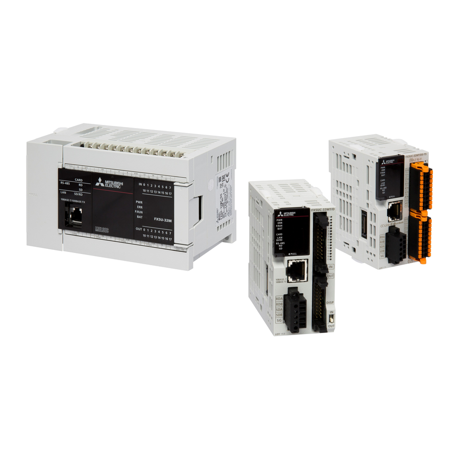
Mitsubishi Electric MELSEC iQ-F Series User Manual
Programmable controller
Hide thumbs
Also See for MELSEC iQ-F Series:
- User manual (282 pages) ,
- Handbook (132 pages) ,
- Programming manual (128 pages)
Table of Contents
Advertisement
Quick Links
Advertisement
Table of Contents
Troubleshooting

Related Manuals for Mitsubishi Electric MELSEC iQ-F Series


Summary of Contents for Mitsubishi Electric MELSEC iQ-F Series
- Page 1 MELSEC iQ-F FX5-ENET/IP User's Manual...
-
Page 3: Safety Precautions
SAFETY PRECAUTIONS (Read these precautions before use.) Before using this product, please read this manual and the relevant manuals introduced in this manual carefully and pay full attention to safety in order to handle the product correctly. This manual classifies the safety precautions into two categories: [ WARNING] and [ CAUTION]. - Page 4 WARNING ● Do not write any data to the "system area" and "write-protect area" of the buffer memory in the intelligent function module. Executing data writing to the "system area" or "write-protect area" may cause malfunction of the programmable controller alarm. For the "system area" or "write-protect area", refer to Page 136 Buffer Memory.
- Page 5 [INSTALLATION PRECAUTIONS] CAUTION ● Do not touch the conductive parts of the product directly. Doing so may cause device failures or malfunctions. ● When drilling screw holes or wiring, make sure that cutting and wiring debris do not enter the ventilation slits of the PLC.
- Page 6 [WIRING PRECAUTIONS] CAUTION ● Perform class D grounding (grounding resistance: 100 Ω or less) of the grounding terminal on the CPU module and extension modules with a wire 2 mm or thicker. Do not use common grounding with heavy electrical systems (refer to the User's Manual (Hardware) of the CPU module used). ●...
- Page 7 CPU module in case of a communication failure. ● Do not disassemble or modify the PLC. Doing so may cause fire, equipment failures, or malfunctions. For repair, contact your local Mitsubishi Electric representative. CAUTION ●...
- Page 8 [DISPOSAL PRECAUTIONS] CAUTION ● Please contact a certified electronic waste disposal company for the environmentally safe recycling and disposal of your device. [TRANSPORTATION PRECAUTIONS] CAUTION ● The PLC is a precision instrument. During transportation, avoid impacts larger than those specified in the general specifications of the User's Manual (Hardware) of the CPU module by using dedicated packaging boxes and shock-absorbing palettes.
-
Page 9: Introduction
If in doubt about the operation or use, please consult the nearest Mitsubishi Electric representative. • Mitsubishi Electric will not accept responsibility for actual use of the product based on these illustrative examples. • This manual content, specification etc. may be changed, without a notice, for improvement. -
Page 10: Table Of Contents
CONTENTS SAFETY PRECAUTIONS ..............1 INTRODUCTION . - Page 11 Network configuration settings ............. . 73 Setting Target Instance .
- Page 12 TCP/IP Interface ............... . 158 Ethernet Link .
-
Page 14: Relevant Manuals
RELEVANT MANUALS Manual name <manual number> Description MELSEC iQ-F FX5 User's Manual (Startup) Performance specifications, procedures before operation, and troubleshooting of the <JY997D58201> CPU module. MELSEC iQ-F FX5U User's Manual (Hardware) Describes the details of hardware of the FX5U CPU module, including input/output <JY997D55301>... - Page 15 Manual name <manual number> Description Transition from MELSEC FX3U, FX3UC Series to MELSEC iQ-F Describes the transition from MELSEC FX3U/FX3UC series to MELSEC iQ-F series. Series Handbook <JY997D66201>...
-
Page 16: Terms
TERMS Unless otherwise specified, this manual uses the following terms. For details on the FX3 devices that can be connected with the FX5, refer to the User’s Manual (Hardware) of the CPU module to be used. Terms Description ■Devices Generic term for FX5U and FX5UC PLCs Generic term for FX3S, FX3G, FX3GC, FX3U, and FX3UC PLCs FX5 CPU module Generic term for FX5U CPU module and FX5UC CPU module... - Page 17 Abbreviation of Secure Digital Memory Card. Device that stores data using flash memory. Peripheral device Generic term for engineering tools and GOTs Generic term for Mitsubishi Electric Graphic Operation Terminal GOT1000 and GOT2000 series ■Software packages Engineering tool The product name of the software package for the MELSEC programmable controllers...
-
Page 18: Chapter 1 Outline
OUTLINE FX5-ENET/IP Ethernet module (hereinafter referred to as FX5-ENET/IP) is an intelligent function module for connecting to a EtherNet/IP network and general-purpose Ethernet. EtherNet/IP communication The module can communicate seamlessly with an EtherNet/IP network by using the communication protocol CIP. FX5-ENET/IP functions as a scanner (originator/client) or an adapter (target/server) of the EtherNet/IP network. - Page 19 MEMO 1 OUTLINE...
-
Page 20: Chapter 2 Specifications
SPECIFICATIONS This chapter describes the FX5-ENET/IP specifications. General Specifications The items other than the following are equivalent to those of the CPU module. For the general specification, refer to the following manual. MELSEC iQ-F FX5U User's Manual (Hardware) MELSEC iQ-F FX5UC User's Manual (Hardware) Items Specifications Dielectric withstand voltage... -
Page 21: Performance Specifications
Performance Specifications The following table lists the performance specifications. Items Specifications EtherNet/IP Class 1 Communication format Standard EtherNet/IP communications communications Number of connections Communication data size 1444 bytes (per connection) Connection type Point-to-point, multicast RPI (communication cycle) 2 to 60000 ms PPS (communication processing 3000 pps (case of 128 bytes) performance) - Page 22 *1 The total number of connections for Class 3 communications and UCMM communications is 32. *2 This size is the maximum size which can be specified to 'Data length' of Class1 communication input data area of the request command during the client operation. During the sever operation, since the FX5-ENET/IP automatically responds according to the request command received from the client, the maximum size is not prescribed.
-
Page 23: Part Names
Part Names This chapter describes the names of each part of the FX5-ENET/IP. 2-4.5 mounting holes [10] [11] [12] [13] Name Description External ground terminal Connect an external ground. (Spring clamp terminal block) Link status display LEDs Displays the link status of module. (Page 22 LED display) Extension cable Cable for connecting the module when adding the FX5-ENET/IP Direct mounting hole... -
Page 24: Led Display
LED display The following table lists the LED display. LED display LED color Description Green, Red Indicates the error status of the EtherNet/IP device. ■LED color: Green • On: Data communication possible • Flashing: No parameter setting • Off: Power failure occurred ■LED color: Red •... -
Page 25: Chapter 3 Procedures Before Operation
PROCEDURES BEFORE OPERATION This chapter describes the procedures before operation. EtherNet/IP communication Checking the specifications of the FX5-ENET/IP Check the specifications of the FX5-ENET/IP. (Page 18 SPECIFICATIONS) Installation of the FX5-ENET/IP Connect the FX5-ENET/IP to the CPU module. For details, refer to the following. MELSEC iQ-F FX5U User's Manual (Hardware) MELSEC iQ-F FX5UC User's Manual (Hardware) Configuring a network... -
Page 26: Chapter 4 Function
FUNCTION The following table lists the function available for the FX5-ENET/IP. Function List EtherNet/IP communication functions Function Description Reference Class1 instance communications Periodically performs data communications between the FX5-ENET/IP and the EtherNet/IP Page 27 device to which the connection has been established using an instance ID. Data communications are performed between the originator that sends the connection request and the target that receives the connection request. -
Page 27: Ethernet/Ip Communication Functions
EtherNet/IP Communication Functions The EtherNet/IP communication functions are used to perform data communications over a network between the FX5-ENET/ IP and EtherNet/IP devices. The FX5-ENET/IP can perform the following types of EtherNet/IP communications. • Class1 communications • Class3 communications • UCMM communications Class1 communications With Class1 communications, data communications are performed periodically by establishing connections between the FX5- ENET/IP and EtherNet/IP devices over a network. - Page 28 Applied connection of EtherNet/IP communications ■When the FX5-ENET/IP is the target : Requests can be accepted from the EtherNet/IP device, : Requests cannot be accepted from EtherNet/IP device, : No combination EtherNet/IP Connection settings communications Connection Trigger type Input type Output type type (target to originator)
-
Page 29: Class1 Instance Communications
Class1 instance communications Function overview Class1 instance communications is a function for periodically performing data communication between the FX5-ENET/IP and an EtherNet/IP device over a connection that has been established using an instance ID. Data communications are performed between the originator (the device on the sending side that requests the connection) and the target (the device on the receiving side that is requested to connect). - Page 30 ■When the connection type is Input Only Scanner Adapter Adapter FX5-ENET/IP EtherNet/IP device Originator Target Buffer memory Transmitted data 'Class1 communications input data area' (Un\G12000 to Un\G35999) EtherNet/IP device Target Transmitted data (1) Connection open (2) Response ■When the connection type is Listen Only Scanner 1 Adapter Scanner 2...
- Page 31 • Listen Only is a connection for the target of which connection such as Exclusive Owner and Input Only that is set for multicast communications is already opened. It can receive only multicast-type data sent to the FX5-ENET/IP. • The connection of Listen Only cannot be opened when the connection such as Exclusive Owner and Input Only that is set for multicast communications is not opened.
- Page 32 Data sending Data is sent from the originator to the target. Data can be sent when the connection type is Exclusive Owner. ■Sending data with the Cyclic trigger type Data transmission can be repeated periodically. CPU module FX5-ENET/IP EtherNet/IP device Originator Target 'Class1...
- Page 33 Data receiving Data is received by the originator from the target. CPU module FX5-ENET/IP EtherNet/IP device Originator Target 'Class1 communications Device input data area' (Un\G12000 to Un\G35999) (1) Turn on 'EtherNet/IP communication start request' (Un\G37.b0) (2) Connection open (3) Response (normal) (4) Receiving data (5) Store the data received at the RPI interval (6) Transfer the stored data with a program...
- Page 34 Setting method For Class1 instance communications, set the originator and target on the FX5-ENET/IP on the scanner side. ■Originator (on scanner side) settings Under "Basic Setting" in the GX Works3, set the IP address, subnet mask, and default gateway of the FX5-ENET/IP. [Navigation window] ...
- Page 35 Assurance of input/output data The data received from EtherNet/IP devices and the data transmitted to EtherNet/IP devices can be assured for each connection. The data assurance is enabled by setting the buffer memory and acquiring the input data and setting the output data using the following module FBs.
-
Page 36: Class3 Message Communications
Class3 message communications Function overview Class3 message communications is a function for performing message communications between the FX5-ENET/IP and an EtherNet/IP device over a connection that has been established by specifying the message communication destination with an instance ID. Class3 message communication supports the server functions. ■Server function With the server function, message communication support commands are used to communicate with arbitrary timing. - Page 37 Server function With the Class3 message communication server function, when the FX5-ENET/IP receives a command request from an EtherNet/IP device, the FX5-ENET/IP executes the command processing and returns the command response. FX5-ENET/IP EtherNet/IP device Server Client (1) Turn on 'EtherNet/IP communication start request' (Un\G37.b0) (2) Connection open (3) Response (normal) (4) Command request...
- Page 38 Setting method Set the server for the FX5-ENET/IP that performs Class3 message communications. Under "Basic Setting" in the GX Works3, set the IP address, subnet mask, and default gateway of the FX5-ENET/IP. [Navigation window] [Parameter] [Module Information] [FX5-ENET/IP] [Basic Setting] For details on the setting window, refer to the following.
- Page 39 Execute the command request of Class3 message communications in the "Online Action" window. [Network][Online Action] For details on the setting window, refer to the following. Page 69 "Online Action" window Commands for message communications can be requested from software made by other companies. When requesting commands from software made by other companies, refer to the manual of the software used.
-
Page 40: Ucmm Message Communications
UCMM message communications Function overview UCMM message communications is a function for performing message communications between the FX5-ENET/IP and an EtherNet/IP device by specifying the message communication destination with an instance ID and not by establishing a connection. UCMM message communication supports the client and server functions. ■Client function With the client function, the buffer memory is used to communicate with arbitrary timing. - Page 41 Client function With the UCMM message communication client function, the buffer memory of the FX5-ENET/IP is used to send command requests to and receive command responses from the EtherNet/IP device. The client function can be used to access the services of each EtherNet/IP device and thereby read and write items such as the data and parameters with arbitrary timing.
- Page 42 Server function With the UCMM message communication server function, when the FX5-ENET/IP receives a command request from an EtherNet/IP device, the FX5-ENET/IP executes the command processing and returns the command response. FX5-ENET/IP EtherNet/IP device Server Client (1) Turn on 'EtherNet/IP communication start request' (Un\G37.b0) (2) Command request (3) Command processing execution (4) Command response...
- Page 43 Communication method ■When the client function is used Execute a command request from the FX5-ENET/IP by operating a program that uses the buffer memory. For program example of UCMM message communications, refer to the following. Page 105 Program Example of UCMM Message Communications ■When the server function is used Open the connection from the client side, and execute the command request.
-
Page 44: Communication Status Setting Function When A Cpu Stop Error Occurs
Communication Status Setting Function When a CPU Stop Error Occurs Each FX5-ENET/IP can be set to stop or continue EtherNet/IP communications when a stop error occurs on the CPU module which the FX5-ENET/IP is mounted on. Therefore, EtherNet/IP communications can be continued even when the stop error occurring CPU module goes into the STOP state. -
Page 45: Chapter 5 System Configuration
SYSTEM CONFIGURATION EtherNet/IP Configuration Network topology EtherNet/IP consists of the FX5-ENET/IP (1) and EtherNet/IP devices (2). For the FX5-ENET/IP, configure the network in star topology, or line topology using the Ethernet cables. Ring topologies are not possible. ■Star topology The network is configured into a star shape using a switching hub and Ethernet cables. ■Line topology The network is configured into a line using Ethernet cables. -
Page 46: General-Purpose Ethernet Communication Configuration
General-purpose Ethernet Communication Configuration For details on general-purpose Ethernet communication configuration, refer to MELSEC iQ-F FX5 User's Manual (Ethernet Communication). Available Software Packages To configure the settings of the FX5-ENET/IP, the GX Works3 and EtherNet/IP Configuration Tool for FX5-ENET/IP are required. -
Page 47: Chapter 6 Wiring
WIRING Grounding Perform the following. • Perform class D grounding (Grounding resistance: 100 Ω or less). • Ground the PLC independently when possible. • If the PLC cannot be grounded independently, perform the "Shared grounding" shown below. Other Other Other equipment equipment equipment... - Page 48 The wires to connect the spring clamp terminal block are described below. No. of wire per terminal Wire size Single wire, strand wire Ferrule with insulation sleeve One wiring AWG24 to 16 AWG23 to 19 (0.2 to 1.5 mm (0.25 to 0.75 mm ■Wire end treatment Strip the cable about 10 mm from the tip to connect a wire ferrule at the stripped area.
-
Page 49: Wiring Method
Wiring Method This section describes how to connect and disconnect the Ethernet cable. Connecting the cable Turn the power supply of FX5-ENET/IP (CPU module) and external device off. Push the Ethernet cable connector into the FX5-ENET/IP until it clicks. Pay attention to the orientation of the connector. Lightly pull the connector to check that the connector is securely connected. -
Page 50: Wiring Products
Wiring Products This section describes the devices used to comprise a network. Ethernet cable Use Ethernet cables that meet the following standards. ■EtherNet/IP Communication Specifications Connector Ethernet standard speed 100 Mbps Ethernet cable: Category 5 or higher (STP cable RJ45 connector 100BASE-TX ■General-purpose Ethernet Communication... -
Page 51: Chapter 7 Parameter Settings
PARAMETER SETTINGS This section explains the parameter settings necessary for EtherNet/IP and general-purpose Ethernet communications with FX5-ENET/IP. For details on each operation of GX Works3, refer to GX Works3 Operating Manual. Procedure for Setting Parameters Add the "Information Module (FX5-ENET/IP)" in the GX Works3. [Navigation window] ... -
Page 52: Required Settings
Required Settings Set the operation mode of the FX5-ENET/IP. Mode Set the operation mode of the FX5-ENET/IP. Item Description Setting range Communication Mode Sets the operation mode of the FX5-ENET/IP. • Online • Online: Normal operation mode • Hardware Test •... - Page 53 Own Node Setting Set the IP address of the FX5-ENET/IP. Item Description Setting range IP Address IP Address Sets the IP address of the FX5-ENET/IP • Blank Setting Set the class and subnet address of the FX5-ENET/IP to the same settings •...
- Page 54 External Device Configuration Set the conditions of the external devices with which the module will communicate through general-purpose Ethernet. Double-click <Detailed Setting> of the "External Device Configuration". Drag and drop an "Ethernet Device" in the "Module List" to the left side of the screen, and set the following items. The setting items vary depending on the “Ethernet Device”...
-
Page 55: Application Settings
Application Settings Set the following parameters when the functions of the general-purpose Ethernet will be used on FX5-ENET/IP. Security Set the security function. Item Description Setting range IP Filter IP Filter Set whether to enable the IP filter function. • Not Use Settings •... -
Page 56: Setting Ethernet/Ip Communications (Starting Ethernet/Ip Configuration Tool For Fx5-Enet/Ip)
Setting EtherNet/IP Communications (Starting EtherNet/IP Configuration Tool for FX5-ENET/IP) Start EtherNet/IP Configuration Tool for FX5-ENET/IP, and then set EtherNet/IP communications. For details, refer to the following. Page 55 EtherNet/IP Configuration Tool for FX5-ENET/IP • Even if the GX Works3 is closed while EtherNet/IP Configuration Tool for FX5-ENET/IP is starting, it can operate independently. -
Page 57: Chapter 8 Ethernet/Ip Configuration Tool For Fx5-Enet/Ip
EtherNet/IP Configuration Tool for FX5-ENET/IP This chapter describes operations of EtherNet/IP Configuration Tool for FX5-ENET/IP. Window Structure The following figure shows the window structure. Name Reference Menu Page 56 EtherNet/IP setting Page 63 Device Library Page 65 Network Detection Page 67 Network configuration setting Page 73 Operation information list... -
Page 58: Menu
Menu The following table lists the menu items of EtherNet/IP Configuration Tool for FX5-ENET/IP. Item Description Reference File Saves a project and configures print setting and window structure. Page 56 Description Sets the FX5-ENET/IP information. Page 60 Library Performs operations such as adding EDS files, displaying EDS file information, and adding EtherNet/IP devices. Page 60 Network Performs operations such as detecting EtherNet/IP devices on the network to add them to the network... - Page 59 ■"Preview or Print Listings" window Print the information of the current network configuration settings. [File] [List and Print] Item Description [Preview] button Displays the information of the network configuration settings in a text file. [Print] button Prints the selected information. [Help] button Displays the help.
- Page 60 ■Structure setting check window Verify the information of the network configuration settings saved on the FX5-ENET/IP (EipConfData.BIN) against the information of the network configuration settings of EtherNet/IP Configuration Tool for FX5-ENET/IP (EipConfData.BIN) to check whether they are the same. [File] [Verify] Item Description Setting range...
- Page 61 ■Upload window The information of the network configuration settings saved on the FX5-ENET/IP is read. [File] [Upload] Item Description Setting range IP Address Displays the IP address of the FX5-ENET/IP. User Name Displays the name. (Fixed to MELSEC.) Password Displays the password.
- Page 62 Description Set the FX5-ENET/IP information. Item Description Adds the FX5-ENET/IP information. (The FX5-ENET/IP information can be added when the existing information is deleted using "Delete".) Delete Deletes the FX5-ENET/IP information. Properties Opens the "Element Properties" window. (Page 63 "Element Properties" window) *1 This action can be performed when WorkStation is selected in the EtherNet/IP setting.
- Page 63 Network Perform operations such as detecting EtherNet/IP devices on the network to add them to the network configuration settings and configuring the settings for EtherNet/IP communications. This item can be selected when EtherNet/IP Configuration Tool for FX5-ENET/IP is switched to the online state and "Network Detection"...
- Page 64 Device Perform operations such as adding the selected EtherNet/IP device to the network configuration settings, configuring the settings for EtherNet/IP devices, and enabling diagnostic mode. Item Description Duplicate Adds a copy of the selected EtherNet/IP device to the network configuration settings. Delete Deletes the selected EtherNet/IP device from the network configuration settings.
-
Page 65: Ethernet/Ip Setting
EtherNet/IP setting EtherNet/IP setting displays the project information of the FX5-ENET/IP set with EtherNet/IP Configuration Tool for FX5- ENET/IP. "Element Properties" window Set the IP address of the FX5-ENET/IP. Set the same IP address as that set in "Basic Setting" in the GX Works3. Select "FX5-ENET/IP"... - Page 66 "Configuration Manager" window Manage the project of EtherNet/IP Configuration Tool for FX5-ENET/IP. Right-click "Ethernet/IP Network" in the EtherNet/IP setting [Configuration Manager] Item Description Active Configuration Displays the name of the currently active project. Configuration Path Displays the storage location of the currently active project file. [New] button Creates a new project.
-
Page 67: Device Library
Device Library "Device Library" lists the EtherNet/IP devices added in EtherNet/IP Configuration Tool for FX5-ENET/IP. The EtherNet/IP devices added to "Device Library" can be added to the network configuration settings. When EtherNet/IP device information is displayed at execution of Network Detection, the information of the EtherNet/IP devices added to "Device Library"... - Page 68 EDS file information The EDS file information of the EtherNet/IP device is displayed. Select the EtherNet/IP device in "Device Library" [Library] [Properties] Item Description [View or Print EDS File] button Displays EDS file information in the text format. 8 EtherNet/IP Configuration Tool for FX5-ENET/IP 8.1 Window Structure...
-
Page 69: Network Detection
Network Detection "Network Detection" detects EtherNet/IP devices on the network and configures EtherNet/IP communication settings online. Detecting the FX5-ENET/IP and EtherNet/IP devices Scan the network to detect the FX5-ENET/IP and EtherNet/IP devices on the "Network Detection" tab. Select the [Network Detection] tab ... - Page 70 EtherNet/IP device properties The properties of an EtherNet/IP device in "Network Detection" is displayed. Select the EtherNet/IP device module in "Network Detection".[Network][Properties] This window shows properties of an EtherNet/IP device to which a module can be mounted. No properties are displayed for EtherNet/IP devices to which a module cannot be mounted. Item Description EDS Name...
- Page 71 "Online Action" window The "Online Action" window is used to perform Class3 message communications and UCMM message communications. Items in this window can be used when EtherNet/IP Configuration Tool for FX5-ENET/IP is switched to the online state. (Page 56 File) Select the [Network Detection] tab ...
- Page 72 Item Description Setting range [Send to Device] button Starts Class3 communications and UCMM communications. Continue (500ms) When this check box is selected, Class3 communications and UCMM • Selected communications will be executed repeatedly at intervals of 500 ms. • Not selected (Default: Not selected) Messaging Selects the communication method.
- Page 73 ■[Port Configuration] tab Read and write the connection status of the EtherNet/IP device. This tab can be used when the "Online Action" window is displayed with an EtherNet/IP device selected. Item Description [Get Values from Device] button Reads and displays the connection status of the EtherNet/IP device. Physical Interface Instance Specifies the port number from the list when the EtherNet/IP device is configured with multiple ports.
- Page 74 ■[Ping] tab Check for the existence of the EtherNet/IP device with the specified IP address over EtherNet/IP. Item Description Setting range Address IP Address Specifies the IP address of the EtherNet/IP device to ping. 0.0.0.0 to 255.255.255.255 (Default: Current IP address of the EtherNet/IP device) ...
-
Page 75: Network Configuration Settings
Network configuration settings Network configuration settings are used for check the EtherNet/IP device settings and the connection status. Display content The network configuration settings is displayed. Display area Display example Display description (Fixed to the display shown on the Ethernet left) ... - Page 76 "Display Option" window The display of the network configuration settings can be changed. [Device] [Options] Item Description Setting range Display Catalog or Product Name Changes the display method according to the EtherNet/IP device • Product Name product name. • Catalog Name Select the "Catalog Name"...
- Page 77 "Channel Properties" window The information of the EtherNet/IP devices set in the network configuration settings is displayed. Select "Ethernet" in the network configuration settings [Device] [Properties] *1 For names of each display, refer to the following. Page 73 Display content ■[General] tab The basic information related to the communications of the FX5-ENET/IP is displayed.
- Page 78 ■[EtherNet/IP] tab Configure settings related to the connection between the FX5-ENET/IP and the EtherNet/IP device. The [EtherNet/IP] tab can be set when "Advanced Mode" is selected. (Page 56 File) Item Description Setting range Timeout FW_Open IO Connection Timing Sets the response waiting time for the connection open request sent 5000 to 8335840 from the FX5-ENET/IP to the EtherNet/IP device during Class1 (Default: 5000)
- Page 79 ■[Module Informations] tab The parameters of the FX5-ENET/IP is displayed. The [Module Informations] tab can be checked when EtherNet/IP Configuration Tool for FX5-ENET/IP is switched to the online state. (Page 56 File) Item Description [Get Informations from Module] button Updates the displayed parameters of the FX5-ENET/IP. Object Selects the parameter type of the FX5-ENET/IP.
- Page 80 • When "Identity" is selected for "Object" Item Description Identification Vendor ID Displays the vendor code of the FX5-ENET/IP. (Fixed to 161.) Device Type Displays the module type of the FX5-ENET/IP. (Fixed to 12.) Product Code Displays the product code of the FX5-ENET/IP. (Fixed to 10.) Revision Displays the version of the FX5-ENET/IP.
- Page 81 • When "TCP/IP Interface" is selected for "Object" Item Description Status Displays the presence of settings related to TCP/IP. • 0: No settings present. • 2: Settings present. Configuration Capability Displays the settings related to services. • Configuration Settable (fixed) Startup Configuration Displays the reference for settings related to TCP/IP on startup.
- Page 82 • When "Ethernet Link" is selected for "Object" Item Description General Interface Speed Displays the communication speed of EtherNet/IP communications. Link Status Displays the link status of EtherNet/IP communications. Duplex Mode Displays the communication method (full-duplex/half-duplex) of EtherNet/IP communications. Negotiation Status Displays the auto-negotiation status.
- Page 83 IP address management window Information such as the IP address of the FX5-ENET/IP is displayed. Set the address of the FX5-ENET/IP with the module parameters of the GX Works3. (Page 50 Basic Setting) Select the EtherNet/IP module display in the network configuration settings ...
- Page 84 EtherNet/IP device setting window (Class1 instance communications) Set the parameters of the EtherNet/IP device used in Class1 instance communications. Select the EtherNet/IP display in the network configuration settings. [Device] [Properties] *1 For names of each display, refer to the following. Page 73 Display content Depending on the connected EtherNet/IP device, some tabs may not be displayed in the EtherNet/IP device setting window.
- Page 85 Item Description Setting range Device Device Name Sets the name to use in management with EtherNet/IP Configuration Up to 50 characters Designation Tool for FX5-ENET/IP. (Default: Refer to the left.) By default, names of EtherNet/IP devices not registered in the network configuration setting are displayed in the form such as "DEVICE-A"...
- Page 86 ■[Chassis] tab Set the modules to be mounted in each slot for EtherNet/IP devices to which modules can be mounted. Item Description Chassis Type [Set Chassis Size in the Module] Selects the number of slots to which modules can be mounted. Available in the button For the setting range and the default value, refer to the manuals of the EtherNet/IP device.
- Page 87 ■[Connections] tab Set items such as the communication content when the connection with the EtherNet/IP device is established. Item Description Configured Connections Displays the connection status of the devices or modules of the EtherNet/IP device. Connection Parameters Displays the parameters of the EtherNet/IP device selected under "Configured Connections". •...
- Page 88 • "General" window Item Description Setting range Connection Bit Health Offset Displays the connection number of the EtherNet/IP device. Connection numbers of EtherNet/IP devices are assigned from 1 in the order in which they were added. • × 4 Time-out Multiplier Specifies the monitoring time of the send/receive timeout as an RPI •...
- Page 89 Item Description Setting range Output-O->T Output Size Specifies the size of the output data. (Unit: Bytes) 0 to 1444 (Default: Varies depending on the EtherNet/IP device) Output Mode Specifies the target to which the output data is written. • Point to Point •...
- Page 90 • "Check Device Identity" window Item Description Setting range Check Identity Specifies the policy of the consistency check. The connection is • Disable disconnected if the check results in a mismatch. • Must Match Exactly • Disable: The check is not performed. •...
- Page 91 ■[Online Parameters] tab Read and write information such as the error information in EDS files. Item Description [Synchronize] button Displays the following window for reading and writing values displayed on the [Online Parameters] tab for the EtherNet/IP device. • Send Values (EIP-CT to Device): Writes the values displayed on the [Online Parameters] tab to the EtherNet/IP device.
- Page 92 ■[Module Informations] tab The parameters of the EtherNet/IP device are displayed. Items in this window can be used when EtherNet/IP Configuration Tool for FX5-ENET/IP is switched to the online state. (Page 56 File) Item Description [Refresh] button Updates the displayed parameters of the EtherNet/IP device. All the initial values are displayed as "###".
- Page 93 ■[Port Configuration] tab Read and write the connection status of the EtherNet/IP device. Item Description [Get Values from Device] button Reads and displays the connection status of the EtherNet/IP device. Physical Interface Instance Specifies the port number from the list when the EtherNet/IP device is configured with multiple ports. [Refresh] button Updates the port number of the "Physical Interface Instance".
- Page 94 ■[Diagnostic] tab The connection status of the EtherNet/IP device is displayed. This tab can be used when diagnostic mode is enabled. (Page 116 Network diagnostics of EtherNet/IP Configuration Tool for FX5-ENET/IP) To display this content, 'EtherNet/IP communication start request' (Un\G37.b0) must be turned off and on and 'EtherNet/IP communication in process' (Un\G35.b0) must be in the ON state.
- Page 95 • Diagnostic information window Item Description Status Input Status Displays the internal status code of the input connection. Output Status Displays the internal status code of the output connection. General Displays the CIP general status code. Extended Displays the CIP extended status code. Counter Frame Error Counter Displays the number of frames that could not be sent/received.
- Page 96 *1 For details on the displayed content, refer to the EtherNet/IP specifications issued by ODVA (www.odva.org). *2 This item is displayed when "Advanced Mode" is selected. (Page 56 File) • I/O data window Item Description Input [..] button Changes the display format of the input data. Length(bytes) Displays the size of the input data.
- Page 97 • Status value The following table lists the values of the "Input Status", "Output Status", and "Status" displayed in the diagnostic information window and I/O data window. When the FX5-ENET/IP is scanner Status value Description EtherNet/IP communications are being performed normally. A timeout has occurred.
-
Page 98: Setting Target Instance
Setting Target Instance If the FX5-ENET/IP is set as the target of the EtherNet/IP communication, select "Target (Class1 Instance)", and drag and drop it to the Network configuration setting. Item Description Setting range Device Designation Device Name Sets the name to use in management with EtherNet/IP Configuration Up to 50 characters Tool for FX5-ENET/IP. -
Page 99: Operation Information List
Operation information list This list displays information such as the operations performed in EtherNet/IP Configuration Tool for FX5-ENET/IP and error messages. "Output Message View Configuration" window Set the information to be displayed in the operation information list. [File] [Message View] [Configuration] Item Description Setting range... -
Page 100: Procedure For Registering Ethernet/Ip Devices
Procedure for Registering EtherNet/IP Devices This section describes the procedure for registering EtherNet/IP devices to the EtherNet/IP communication settings. The following two methods can be used to register EtherNet/IP devices. • Configuring settings online (Page 101 Configuring settings online) • Configuring settings offline (Page 101 Configuring settings offline) Adding the EDS file Follow the EDS Management wizard to add EtherNet/IP devices to "Device Library". - Page 101 Select EDS files to add and click the [Next] button. Item Description Setting range Add File(s) Select this item to add the selected EDS files. (Multiple EDS files can • Selected be added at a time.) • Not selected Click the [Browse] button and select EDS files. (Default: Selected) Add all the EDS from the Directory Select this item to add all EDS files in the selected folder.
- Page 102 The "EDS Management" window displays the additional result of the EDS files added to "Device Library". Check that the files have been properly added and click the [Next] button. (When the files have been properly added, OK is displayed in the "Status" field.) Selecting an added EDS file and clicking the [View Selected File] button displays information of the EDS file in a text file.
-
Page 103: Configuring Settings Online
Configuring settings online When setting EtherNet/IP devices online, the following conditions must be met. • The FX5-ENET/IP and EtherNet/IP device are connected to the network. • A name has been set to the EtherNet/IP device, and the name does not duplicate the name of other EtherNet/IP devices. •... -
Page 104: Checking The Software Version
Checking the Software Version Check the software version of EtherNet/IP Configuration Tool for FX5-ENET/IP in the following window. [Help] [About] 8 EtherNet/IP Configuration Tool for FX5-ENET/IP 8.3 Checking the Software Version... -
Page 105: Chapter 9 Programming
PROGRAMMING This chapter describes program examples of Class 1 instance communications and UCMM message communications. For program examples of general-purpose Ethernet communication, refer to MELSEC iQ-F FX5 User's Manual (Ethernet Communication). Program Example of Class 1 Instance Communications This section describes examples of Class 1 instance communications. Program example By turning on the request command while Class1 communications are being executed, the connection information is read and written. - Page 106 Program of the FX5-ENET/IP (writes the connection information) ■Devices used in the program Device Description M1001 Execution command M1002 Execution status M1003 Normal completion D1001 Error code D1002 Error code of connection communication error D1003 Output data storage device (head number of the device) ■Program example 9 PROGRAMMING 9.1 Program Example of Class 1 Instance Communications...
-
Page 107: Program Example Of Ucmm Message Communications
Program Example of UCMM Message Communications This section provides a program example using the client function of UCMM message communications. Program example The following example shows a program to execute UCMM message communications by turning on the UCMM command send request (M100) in the program. Labels used in the program Classification Label name... - Page 108 Program example (0) Communication start processing (8) Send processing of command setting and command request of UCMM message communications (80) Acquire processing of command response of UCMM message communications 9 PROGRAMMING 9.2 Program Example of UCMM Message Communications...
-
Page 109: Chapter 10 Troubleshooting
TROUBLESHOOTING This section contains an explanation of errors that may occur during communication between FX5-ENET/IP and other devices, and troubleshooting for such errors. 10.1 Checking with LEDs This section describes troubleshooting using the LEDs. The error status can be determined by the status of the RUN LED, ERROR LED, and MS LED. RUN LED ERROR LED MS LED... - Page 110 When the NS LED is flashing in green When the NS LED is flashing in green, check the following. Check item Action Have the following buffer memory values been checked? • Check whether the buffer memory values are normal. • Class1 communication status 'Data link status' (Un\G6030 to Un\G6031) •...
-
Page 111: Checking The Module Status
10.2 Checking the Module Status The status of FX5-ENET/IP module can be checked by the following methods. • Module diagnostics • Ethernet diagnostics • Checking the buffer memory • Event history function Module diagnostics The following functions can be used in the "Module Diagnostics" window for the FX5-ENET/IP. Function Application Error Information... - Page 112 Module Information List Switch to the [Module Information List] tab to check various status information of the FX5-ENET/IP. Item Description LED information (Module) Displays the status of the RUN LED and ERROR LED of the FX5-ENET/IP. LED information (Communication) Displays the status of the MS LED and NS LED of the FX5-ENET/IP. Setting information IP Address (1st Octet) Displays the IP address of the FX5-ENET/IP.
-
Page 113: Ethernet Diagnostics
Ethernet diagnostics To check the status of general-purpose Ethernet, parameter setting and communication status, perform the “Ethernet Diagnostics” of GX Works3. [Diagnostics] [Ethernet Diagnostics] Select the "Module" in the [Target Module Specification]. The following functions can be used in the "Ethernet Diagnostics" window for the FX5-ENET/IP. Function Application Status of Each Connection... - Page 114 Status of Each Connection The status of each connection of the FX5-ENET/IP selected. [Diagnostics] [Ethernet Diagnostics] Select the "Module" in the [Target Module Specification]. Select the [Status of Each Connection] tab. Item Description Connection No./Function Displays the connection number and functions. Host Station Port No.
- Page 115 Status of Each Protocol The total number of packets sent/received by each protocol of the selected FX5-ENET/IP can be checked. [Diagnostics] [Ethernet Diagnostics] Select the "Module" in the [Target Module Specification]. Select the [Status of Each Protocol] tab. Item Description Display range...
- Page 116 Connection Status The communication status of the FX5-ENET/IP. [Diagnostics] [Ethernet Diagnostics] Select the "Module" in the [Target Module Specification]. Select the [Connection Status] tab. Item Description Display range Communication Full Duplex/Half Duplex Displays whether the line is full-duplex or half-duplex. Status Connection Status Displays the cable connection status.
-
Page 117: Checking The Buffer Memory
Checking the buffer memory The buffer memories can be used to check for errors that have occurred in FX5-ENET/IP. EtherNet/IP communication error If an error occurs during EtherNet/IP communication, check the following buffer memories. Buffer memory address Buffer memory name Description Un\G6034 to Un\G6035 Class1 communications status abnormal... -
Page 118: Checking The Network Status
10.3 Checking the Network Status Use the following methods to check the EtherNet/IP network status. • Network diagnostics of EtherNet/IP Configuration Tool for FX5-ENET/IP • Checking with the buffer memory • PING test Network diagnostics of EtherNet/IP Configuration Tool for FX5- ENET/IP The network diagnostics of EtherNet/IP Configuration Tool for FX5-ENET/IP can be used to check the connection information of EtherNet/IP devices. - Page 119 Checking the connection information of EtherNet/IP devices This section describes how to check the connection information of EtherNet/IP devices. Setting data Display the EtherNet/IP device setting window. Select the EtherNet/IP display in the network configuration settings. [Device] [Properties] Select the [Diagnostic] tab.
-
Page 120: Checking With The Buffer Memory
Checking with the buffer memory The status of the Class1 communication connections and the error details can be checked with the following buffer memory areas. • Class1 communication status 'Data link status' (Un\G6030 to Un\G6031) • Class1 communication status 'Error status' (Un\G6034 to Un\G6035) •... -
Page 121: Hardware Test
10.4 Hardware Test This section describes how to perform a test related to hardware, such as a ROM/RAM of the FX5-ENET/IP. • During the hardware test, values in the buffer memory cannot be referred from the GX Works3 or the program. -
Page 122: Troubleshooting By Symptom
10.5 Troubleshooting by Symptom The troubleshooting measures for each symptom during EtherNet/IP communication are shown below. If an error has occurred in the FX5-ENET/IP, identify the error cause using the GX Works3. (Page 109 Checking the Module Status) Communications with EtherNet/IP devices cannot be performed The following table lists the actions to be taken if communications with EtherNet/IP devices cannot be performed. - Page 123 EtherNet/IP communications cannot be performed The following table lists the actions to be taken if EtherNet/IP communications (Class1 instance communications, Class3 message communications, UCMM message communications) cannot be performed. ■Class1 instance communications Check item Action Has the EtherNet/IP device to connect been registered in EtherNet/IP If the EtherNet/IP device to connect is not displayed in the network Configuration Tool for FX5-ENET/IP? configuration setting of EtherNet/IP Configuration Tool for FX5-ENET/IP, add...
-
Page 124: List Of Error Codes
10.6 List of Error Codes This section lists the error codes, error details and causes, and actions for the errors that occur in the processing for data communications between the FX5-ENET/IP and external devices or that are caused by processing requests from the CPU module on the own station. - Page 125 Error Error name Error details and causes Action code 10EH to TCP error An error has occurred in TCP • Retry at a later time. 10FH communications. • Check whether the operating status of the external device is normal. • Check for errors in the line status. •...
- Page 126 Error Error name Error details and causes Action code 11FH Memory error An error was detected in the memory. • Take measures to reduce noise. • Reset the CPU module, and then switch it to RUN mode. If the error occurs again even after the above action is taken, the possible cause is a hardware failure of the module on which the error occurred.
- Page 127 Error Error name Error details and causes Action code 137H to Memory error An error was detected in the memory. • Take measures to reduce noise. 138H • Reset the CPU module, and then switch it to RUN mode. If the error occurs again even after the above action is taken, the possible cause is a hardware failure of the module on which the error occurred.
-
Page 128: Module Error
Module error Error codes when a module error occurs are classified into major error, moderate error, and minor error, and can be checked in the [Error Information] tab of the "Module Diagnostics" window of the FX5-ENET/IP. (Page 109 Module diagnostics) The error codes are stored in ‘Latest error code’... - Page 129 Error Error name Error details and causes Action code 1E11H EtherNet/IP An error was detected in the parameters set • Use EtherNet/IP Configuration Tool for FX5-ENET/IP to write the communication error with EtherNet/IP Configuration Tool for FX5- parameters to the module again. ENET/IP.
- Page 130 Error Error name Error details and causes Action code 3056H Socket communication The socket communication buffer for Read out the received data using the dedicated instruction. buffer full receiving has no space. 3095H Parameter error The number of target IP address setting is Please consult your local Mitsubishi representative.
-
Page 131: Ethernet Communication Error
Ethernet communication error The Ethernet communication error codes can be checked in “Status of Each Connection” on the "Ethernet Diagnostics" screen of FX5-ENET/IP. (Page 112 Status of Each Connection) The error codes will be stored in ‘Error code’ (Un\G108 to Un\G139). -
Page 132: List Of Event Code
10.7 List of Event Code The following table lists events that occur in the FX5-ENET/IP. Event Event Event Event Detected event Detailed information code type category status Detailed Detailed Detailed information 1 information 2 information 3 1080 System Error Major ROM write count error... - Page 133 Event Event Event Event Detected event Detailed information code type category status Detailed Detailed Detailed information 1 information 2 information 3 2DA9 System Error Moderate Connection setting parameter Parameter Failure (Communication data code error) information information 2DAA System Error Moderate Connection setting parameter (Error in Parameter...
- Page 134 Event Event Event Event Detected event Detailed information code type category status Detailed Detailed Detailed information 1 information 2 information 3 3E34 System Error Major Fixed memory block acquisition/release Failure parameter error information 3E35 System Error Major The variable memory block acquisition/ ...
-
Page 135: Appendices
APPENDICES Appendix 1 External Dimensions This chapter describes the external dimensions of the FX5-ENET/IP. 2-4.5 Mounting holes (Unit: mm) APPX Appendix 1 External Dimensions... -
Page 136: Appendix 2 Standards
Compliance to EMC directive and LVD directive of the entire mechanical module should be checked by the user/ manufacturer. For more details please contact to the local Mitsubishi Electric sales site. Requirement for compliance with EMC directive... -
Page 137: Appendix 3 Module Label
Appendix 3 Module Label The buffer memory of the FX5-ENET/IP can be set using module label. Structure of the module label The module label name is defined with the following structure. • "instance name"_"data format""label name"_D • "instance name"_"data format""data type"_"label name"_D ■Instance name The following is the instance name of the FX5-ENET/IP. -
Page 138: Appendix 4 Buffer Memory
Appendix 4 Buffer Memory The buffer memory is used to exchange data between the FX5-ENET/IP and the CPU module or EtherNet/IP devices. Buffer memory values are set to their defaults (initial values) when the system is powered off or the CPU module is reset. List of buffer memory addresses Buffer memory address Name... -
Page 139: Details Of Buffer Memory Addresses
Buffer memory address Name Initial value Read, write Decimal Hexadecimal 11434 to 11465 2CAAH to 2CC9H Block assurance Connection 1 to 32 input data update state Read, write specification per 11498 to 11529 2CEAH to 2D09H Connection 1 to 32 output data update state Read, write connection 12000 to 35999... - Page 140 Output signals ■Output signals (Un\G36 to Un\G37) These signals are used for controlling the FX5-ENET/IP. Address Signal name Description Un\G36 Module error clear request Requests to clear the error that has occurred in FX5-ENET/IP. To request to clear the module error, turn off, on and off the signal. Issuing the request after the cause of the error is removed will clear the followings.
- Page 141 ■Operation timing of EtherNet/IP communications The operation timing of the EtherNet/IP communication by turning on ‘Operation is in progress with the setting for continuing EtherNet/IP communications’ (Un\G37.b0) is shown below. When ‘EtherNet/IP data link continuation specification state’ (Un\G5005) is “1: Operation is in progress with the setting for continuing EtherNet/IP communications,”...
- Page 142 • 'EtherNet/IP data link continuation specification' (Un\G5004) is set 'EtherNet/IP data link continuation specification' 0 (Stop specification request) 16 (Continuation setting request) (Un\G5004) 'EtherNet/IP data link continuation specification state' 2 (Stop specification status) 1 (Continuation setting status) (Un\G5005) 'EtherNet/IP communication start request' (Un\G37.b0) 'EtherNet/IP communication in process' (Un\G35.b0)
- Page 143 IP address storage area write request ■IP address storage area write request (Un\G56) Specify whether to write the stored values of ‘IP address setting’ (Un\G50 to Un\G51), ‘Subnet mask pattern setting’ (Un\G52 to Un\G53) and ‘Default router IP address setting’ (Un\G54 to Un\G55) to the IP address storage area. •...
- Page 144 IP address storage area clear error code ■IP address storage area clear error code (Un\G62) Stores error codes if clearing of IP address storage area fails. • 0: Normal (no error) • 1921H: ‘IP address storage area write request’ (Un\G56) and ‘IP address storage area clear request’ (Un\G58) were simultaneously turned off and on.
- Page 145 Default gateway IP address ■Default gateway IP address (Un\G76 to Un\G77) Stores default gateway IP address on the own station set with GX Works3. (Page 50 Basic Setting) The stored values can be changed by the IP address change function. Address Description Un\G76...
- Page 146 Open request signal ■Open request signal (Un\G154 to Un\G155) Open request signal for each connection number of socket communication. Address Connection number Description Un\G154 Connection number 1 • On: Requesting open • Off: No open request Connection number 2 Connection number 16 Un\G155 b0 to b15...
- Page 147 MAC address of the already connected station ■MAC address of the already connected station (Un\G202 to Un\G204) Stores the MAC address of the station, which was connected to the network earlier, in the station with duplicated IP address. Address Description Un\G202 Serial ID Un\G203...
- Page 148 EtherNet/IP data link continuation specification ■EtherNet/IP data link continuation specification (Un\G5004) This address is used to set whether to continue EtherNet/IP communications when 'EtherNet/IP communication start request' (Un\G37.b0) is turned on and off. (Page 42 Communication Status Setting Function When a CPU Stop Error Occurs) Set this address to continue EtherNet/IP communications in situations such as when the CPU module changes from the RUN state to the STOP state and when a stop error occurs on the CPU module.
- Page 149 Class1 I/O data start offset address ■Class1 Start offset address to the input data (Un\G5134 to Un\G5165) In relation to the start address of 'Class1 communications input data area' (Un\G12000 to Un\G35999), stores the offset address of the input data for each connection. •...
- Page 150 Application Trigger ■Application Trigger (Un\G5274 to Un\G5275, Un\G5278 to Un\G5279, Un\G5282 to Un\G5283) This area requests and checks Application Triggers via UCMM communications. Address Name Connection number Description Un\G5274 Application Trigger Connection number 1 Requests Application Trigger for each connection number. Request (UCMM) •...
- Page 151 Class1 communication status ■Class1 communication status (Un\G6030 to Un\G6031, Un\G6034 to Un\G6035) This area stores the communication status of Class1 communications for each connection number. Address Name Connection number Description Un\G6030 Data link status Connection number 1 Stores the data link status of connection numbers 1 to 32. It automatically turns on when communication recovers from an Connection number 2 error.
- Page 152 Block assurance specification per connection ■Connection 1 to 32 input data update state (Un\G11434 to Un\G11465) This area stores the update status of the input data when 'Block assurance state per connection' (Un\G5001) is set to "2: Data assurance is being performed.". •...
- Page 153 UCMM communications input data area ■UCMM communications input data area (Un\G36000 to Un\G59999) This area stores the data received by the FX5-ENET/IP from the EtherNet/IP device during UCMM communications. Address Description Un\G36000 to Connection number 1 input data area Un\G36749 Un\G36750 to Connection number 2 input data area Un\G37499...
- Page 154 UCMM communications output data area ■UCMM communications output data area This area stores the data to send to the EtherNet/IP device from the FX5-ENET/IP during UCMM communications. Address Description Un\G84000 to Connection number 1 output data area Un\G84749 Un\G84750 to Connection number 2 output data area Un\G85499 ...
-
Page 155: Appendix 5 Details Of Message Communication Support Command
Appendix 5 Details of Message Communication Support Command This section describes the commands used during Class3 message communications and UCMM message communications. Object list The following table lists the objects that can be used with message communication support commands. Object Description Reference Identity... - Page 156 ■Data type Indicates the class/instance data type. The data types available in FX5-ENET/IP (determined by the CIP specifications) are shown below. Item Description Data size Range BOOL Bit data 1 byte 0: Off (False) 1: On (True) SINT Signed 8-bit data 1 byte -128 to +127 Signed 16-bit data...
-
Page 157: Identity
Identity Object name Class ID Identity Class attribute (instance ID: 00H) Attribute Access Name Data type Description Setting value (Set)/stored value (Get) Revision UINT Object revision 0001H Max Instance UINT Maximum instance number 0001H Number of instances UINT Number of created instances... - Page 158 ■Details of product status Description Value Owned The word “connection” described below refers to the “Exclusive Owner" connection. (The bit is not changed by an Input Only or Listen Only connection.) • 0: EtherNet/IP communications are not connected as the target device. •...
-
Page 159: Connection Manager
Connection Manager Object name Class ID Connection Manager Class attribute (instance ID: 00H) Attribute Access Name Data type Description Setting value (Set)/stored value (Get) Revision UINT Object revision 0001H Max Instance UINT Maximum instance number 0001H ... -
Page 160: Tcp/Ip Interface
TCP/IP Interface Object name Class ID TCP/IP Interface Class attribute (instance ID: 00H) Attribute Access Name Data type Description Setting value (Set)/stored value (Get) Revision UINT Object revision 0004H Max Instance UINT Maximum instance number 0001H ... - Page 161 ■Details of interface status Description Value 0 to 3 Interface Configuration Status Fixed to 2 (to set the IP address acquired from the parameter settings) Mcast Pending • 0: No changes to TTL Value and Mcast Config • 1: In the wait-for-restart state due to changes to TTL Value and Mcast Config 5 to 31 Reserved Fixed to 0...
-
Page 162: Ethernet Link
Ethernet Link Object name Class ID Ethernet Link Class attribute (instance ID: 00H) Attribute Access Name Data type Description Setting value (Set)/stored value (Get) Revision UINT Object revision 0004H Max Instance UINT Maximum instance number 0001H ... - Page 163 Attribute Access Name Data Description Setting value type (Set)/stored value (Get) Media Alignment Errors UDINT Number of receive frames with lengths 00000000H Counters that are not octet integers FCS Errors UDINT Number of receive frames that do not 00000000H pass the FCS check Single Collisions...
- Page 164 Attribute Access Name Data Description Setting value type (Set)/stored value (Get) HCInOctets ULINT Number of octets received through the 0000000000000 Interface interface 000H Counters HCInUcastPkts ULINT Number of unicast packets received 0000000000000 through the interface 000H HCInMulticastPkts ULINT Number of multicast packets received 0000000000000 through the interface...
-
Page 165: Appendix 6 Processing Time
Appendix 6 Processing Time The data link processing time is explained below. RPI (Requested Packet Interval) FX5-ENET/IP transmits and receives data according to the RPI interval defined by the parameter setting set by EtherNet/IP Configuration Tool for FX5-ENET/IP. The fastest value of RPI is calculated by the following formula based on the PPS of FX5- ENET/IP and the number of connections. - Page 166 ■Receive delay time The concept of receive delay time in Class1 communication mode is shown belo EtherNet/IP device FX5-ENET/IP CPU module Item name Description Sequence scan Time required for refreshing the receive data from the buffer memory on the FX5-ENET/IP to a program.
-
Page 167: Index
INDEX ......43 ......69 Adapter Online Action . -
Page 168: Revisions
First Edition This manual confers no industrial property rights or any rights of any other kind, nor does it confer any patent licenses. Mitsubishi Electric Corporation cannot be held responsible for any problems involving industrial property rights which may occur as a result of using the contents noted in this manual. -
Page 169: Warranty
WARRANTY Please confirm the following product warranty details before using this product. Gratis Warranty Term and Gratis Warranty 2. Onerous repair term after discontinuation of production Range If any faults or defects (hereinafter "Failure") found to Mitsubishi shall accept onerous product repairs for be the responsibility of Mitsubishi occurs during use of seven (7) years after production of the product is the product within the gratis warranty term, the... -
Page 170: Trademarks
TRADEMARKS Microsoft and Windows are either registered trademarks or trademarks of Microsoft Corporation in the United States and/or other countries. Ethernet is a trademark of Xerox Corporation. EtherNet/IP and DeviceNet is a trademark of ODVA, Inc. PROFIBUS is a trademark of PROFIBUS Nutzerorganisation e.V. Anywire and ANYWIREASLINK is a registered trademark of the Anywire Corporation. - Page 172 Manual number: SH(NA)-082027ENG-A Model: FX5-U-ENETIP-E Model code: 09R737 When exported from Japan, this manual does not require application to the Ministry of Economy, Trade and Industry for service transaction permission. HEAD OFFICE: TOKYO BUILDING, 2-7-3 MARUNOUCHI, CHIYODA-KU, TOKYO 100-8310, JAPAN Specifications are subject to change without notice.