Mitsubishi Electric MELSEC iQ-F Series Quick Connection Manual
For cc-link ie field network basic
Hide thumbs
Also See for MELSEC iQ-F Series:
- User manual (282 pages) ,
- Handbook (132 pages) ,
- Programming manual (128 pages)

Related Manuals for Mitsubishi Electric MELSEC iQ-F Series


Summary of Contents for Mitsubishi Electric MELSEC iQ-F Series
- Page 1 FACTORY AUTOMATION Mitsubishi Electric Programmable Controller MELSEC iQ-F Series Quick Connection Guide FREQROL-A800/F800/E800 Series for CC-Link IE Field Network Basic...
-
Page 2: Introduction
If in doubt about the operation or use, please contact your local Mitsubishi Electric representative. • Mitsubishi Electric will not accept responsibility for actual use of the product based on these illustrative examples. Please use it after confirming the function and safety of the equipment and system. -
Page 3: Table Of Contents
CONTENTS INTRODUCTION ................1 RELEVANT MANUALS . -
Page 4: Relevant Manuals
RELEVANT MANUALS The following relevant manuals can be downloaded from the Mitsubishi Electric FA site. https://www.mitsubishielectric.co.jp/fa/ref/ref.html?kisyu=plcf&manual=download_all [: Available, : Not available] Manual name Available form <manual number> e-Manual MELSEC iQ-F FX5U User's Manual (Hardware) <JY997D55301> MELSEC iQ-F FX5UC User's Manual (Hardware) <JY997D61401>... -
Page 5: Key Features
FB (function block) library is a collection of FBs that are used in GX Works3. Various programs required to operate the MELSEC iQ-F series modules can be designed easily by dragging and dropping FBs from the FB library to a program editor and inputting devices, drastically reducing the cost and time required for programming. -
Page 6: Chapter 1 Preparation
PREPARATION Applicable Models The models described in this guide are shown in the following table. Programmable controller Inverter (Ethernet model) FX5U CPU module FX5UC CPU module FX5UJ CPU module FR-E800-E FR-A800-E FR-F800-E Operation Flow Diagram Preparing the required products INVERTER SETTINGS PROGRAMMABLE CONTROLLER SETTINGS FR Configurator2... -
Page 7: Required Products
Required Products In a system configuration example of this manual, two inverters (FR-E800-E) are connected to the FX5U CPU module. FX5U CPU module FR-E800-E × 2 Personal computer and software First inverter Second inverter (Station number 1) (Station number 2) Use an FX5U CPU module that meets the following The PU port can be found when the front cover is GX Works3... -
Page 8: System Configuration
System Configuration This section describes the system configuration in which two inverters (FR-E800-E) are connected to the FX5U CPU module. The inverters are connected into a star type using a switching hub and standard Ethernet cables. When multiple inverters communicate with each other in a same network, the first three values of the IP addresses (first to third octets) need to be the same. -
Page 9: Chapter 2 Inverter Settings
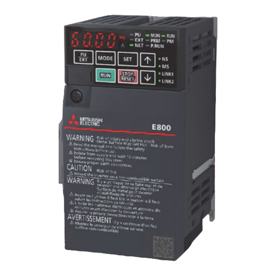
INVERTER SETTINGS Names of the Parts on the Operation Panel Inverter parameter settings and error content can be checked on the operation panel. [10] *: The operation panel cannot be removed from the inverter. Name Description Monitor (4-digit LED) Shows a numeric value (readout) of a monitor item such as the frequency and a parameter number. Unit indication Hz: ON when the actual frequency is monitored. -
Page 10: List Of Related Parameters
List of Related Parameters The following tables list the parameters which are required to be set. To make communications between an inverters and a connected device, set the inverter parameters to match the communication specifications of the connected device. Data communications cannot be made if the settings are not made or if there is any setting error. -
Page 11: Ethernet Parameter Settings
Ethernet Parameter Settings Parameters are set by connecting the inverters and the personal computer over Ethernet. In this manual, FR Configurator2 is used to set the parameters. The following describes how to set the parameters using FR Configurator2. FR-E800-E FR-E800-E Ethernet Start FR Configurator2, and select [Ethernet parameter setting] from the [Tool] menu bar. - Page 12 Select the checkboxes of "Network No. / station No.", "Station No.", and "IP address / subnet mask", and click the [OK] button. In this manual, the following setting values are used. Parameter Setting value Network No. Station No. IP address 192.168.50.11 Subnet mask 255.255.255.0...
-
Page 13: Parameter Settings
Parameter Settings Select [Project] on the toolbar [New]. In the "Connection setting" field, select "Ethernet" for "PC-side port" and "Not used" for "Through", and click the [Auto recognize] button. Click the [Yes] button on the window, which asks whether to clear the current settings, to execute automatic recognition. - Page 14 When the auto-recognized inverter information is displayed, check that the displayed model, capacity, and other information are correct. Click the [OK] button. In the [Project] window, the inverter models of station number 1 and station number 2 are displayed. Double-click "Parameter"...
- Page 15 Enter the parameter setting values. For parameters and setting values to be used, refer to Page 9 List of Related Parameters. For parameter setting on the operation panel, refer to the following. Section 2.1.2 Basic operation of the operation panel in the FR-E800 Instruction Manual (Function). The following parameters are set during Ethernet parameter setting, therefore, entering their setting values is not necessary.
-
Page 16: Writing Data To The Inverters
Writing Data to the Inverters The parameter setting values entered in the parameter list are written to each inverter. Click the following icon on the toolbar to go online. Grayed out when the inverter is offline. Activated when the inverter is online. Click [Batch write], and click the [Yes] button on the window which asks whether to write the parameters. -
Page 17: Inverter Reset
Inverter Reset After the parameters are changed, the inverters must be reset. Otherwise, the changed settings are not reflected. In this manual, FR Configurator2 is used to reset the inverters. The following describes how to reset the inverters using FR Configurator2. -
Page 18: Chapter 3 Programmable Controller Settings
Page 54 Part names Downloading the FB Library In this manual, the FB library for CC-Link IE Field Network Basic compatible inverters is used. To obtain the FB library, please contact your local Mitsubishi Electric representative. 3 PROGRAMMABLE CONTROLLER SETTINGS 3.1 Part Names... -
Page 19: Importing The Fb Library
Importing the FB Library This section describes how to register the obtained FB library to GX Works3. Decompress the FB library folder (zip file) before registering the FB library. Start GX Works3, and select [Project] on the toolbar [New]. In this manual, the following setting values are used. - Page 20 Select the "INVERTER-CC-IEF-Basic_F.mslm" file in the decompressed FB library folder, and click the [Open] button. The selected file is added to [Library] in the "Element Selection" window. If the "Element Selection" window is not displayed, select [View] on the toolbar [Docking Window] [Element Selection] to open the window.
-
Page 21: Parameter Settings
Parameter Settings This section describes how to set parameters required for the programmable controller using GX Works3. To set the parameters, connect the personal computer, the programmable controller, and the inverters over Ethernet. FR-E800-E FR-E800-E FX5U CPU module Ethernet In the "Navigation" window, select [Parameter] [FX5UCPU] [Module Parameter] [Ethernet Port]. If the "Navigation"... - Page 22 Set an IP address and a subnet mask in "Own Node Settings" of "Basic Settings". In this manual, the following setting values are used. (For the setting values, refer to Page 7 System Configuration.) Item Setting value IP Address 192.168.50.2 Subnet Mask 255.255.255.0...
- Page 23 The information of the inverters connected to the programmable controller is reflected in the table. Check the settings of model name, reserved station, IP address, and subnet mask, and click [Close with Reflecting the Setting]. In this manual, the following setting values are used. (For the setting values, refer to Page 7 System Configuration.) Model Name STA# RSVD STA...
- Page 24 Data flow between the master station and slave stations using link devices In this manual, since [Compatible with the octuple setting of CC-Link Ver.2] is selected for the CC-Link extended setting (Pr.544) of the inverters, assign the link devices of each inverter to the following devices of the programmable controller. (For the inverter settings, refer to ...
- Page 25 Mainly-used devices The following tables list the functions and the assignment target device numbers of the mainly-used link devices (remote input, remote output, and remote registers). ■Bit device (X) Device number (Station number 1) Device number (Station number 2) Description X100 X200 Forward running...
- Page 26 ■Word device Device number (Station number 1) Device number (Station number 2) Description Upper 8 bits Lower 8 bits W0000 W0020 First monitor value W0001 W0021 Second monitor value W0002 W0022 Reply code 2 Reply code 1 W0003 W0023 Data to be read W0008 W0028 Fault record No.
-
Page 27: Adding Global Labels
Adding Global Labels This section describes how to add the global labels in the FB library to the project. In the "Element Selection" window, select [Global Label] [INVERTER-CC-IEF-Basic_F] of the imported FB library. Right-click [INVERTER-CC-IEF-Basic_F], and select [Add to Project]. Right-click In the "Navigation"... - Page 28 How to check the global label assignment areas To display the global labels used in the FB library, select [Global Label] [INVERTER-CC-IEF-Basic_F] in [Label], and double-click [INVERTER-CC-IEF-Basic_F]. The following table lists the initial settings of the devices used in the global labels. Label Name Data Type Class...
-
Page 29: Communication Settings Of Gx Works3
Communication Settings of GX Works3 This section describes the communication settings of GX Works3. Directly connect an Ethernet port of the personal computer where GX Works3 has been installed to the FX5U CPU module as shown below. To write data to the FX5U CPU module, a communication test needs to be performed first. - Page 30 Specify an Ethernet adapter of the personal computer which is used when the personal computer is directly connected to the CPU module. When "Not Specified" is set, select an adapter to be used from the drop-down list. After the adapter is selected, click the [Communication Test] button. When the following window appears, click the [OK] button.
-
Page 31: Writing Data To The Programmable Controller
Writing Data to the Programmable Controller This section describes how to write programs and parameters to the programmable controller. The programs and the parameters must be determined before writing them to the programmable controller. Select [Convert] [Rebuild All]. Click the [OK] button. Select [Online] ... - Page 32 Click the [Parameter + Program] button, and click the [Execute] button. When the following window appears, click the [Yes to all] button. After the programs and the parameters are written to the programmable controller, reset or power OFF and ON the programmable controller.
-
Page 33: Chapter 4 Coummunication Check Over Cc-Link Ie Field Network Basic
COUMMUNICATION CHECK OVER CC-Link IE Field Network Basic This chapter describes how to check communications over CC-Link IE Field Network Basic in the system where the inverters and the programmable controller are connected. FR-E800-E FR-E800-E FX5U CPU module Ethernet On GX Works3, select [Online] on the toolbar [Monitor] [Device/Buffer Memory Batch Monitor]. Enter "X100"... -
Page 34: Chapter 5 Example Programs
D120 = 2000 X17 ON Stop In this manual, the FB library provided by Mitsubishi Electric is used. For how to set the FB library, refer to the following. Page 17 Downloading the FB Library Page 18 Importing the FB Library 5 EXAMPLE PROGRAMS 5.1 Operation... -
Page 35: How To Use The Fb Library
How to Use the FB Library The FBs in the imported FB library can be used by selecting an applicable FB in the "Element Selection" window and dragging and dropping it to the program editor. After the FB is pasted, create an input ladder and an output ladder of the pasted FB, and complete a program. - Page 36 Insert a contact and input to B:i_bEN. Insert an FB Word device input to the left side of the FB. Insert an FB Word device output to the right side of the FB. Repeat these steps to create ladders. 5 EXAMPLE PROGRAMS 5.2 How to Use the FB Library...
-
Page 37: Example Programs
Example Programs The following programs are designed to control the inverters (station numbers 1 and 2) using the FB library for CC-Link IE Field Network Basic compatible inverters. This section provides the example programs for the station numbers 1 and 2. Example program for the station number 1 Setting the station number to 1 SM402... - Page 38 Turing ON X7 to stop the output of the station number 1 Stop Execution command command Output stop command Stop Output stop command command Y111 Station number 1 output stop command Execution command Running FB of the station number 1: Outputting the operation control commands to the inverter (station number 1) to operate it. M_INVERTER_CC_IEF_Basic_Running_F_00A_1 Running B:i_bEN...
- Page 39 MonitorStatus FB of the station number 1: Obtaining the whole 16-bit data of the operating status of the inverter (Station number 1) M_INVERTER_CC_IEF_Basic_MonitorStatus_F_00A_1 MonitorStatus B:i_bEN o_bENO:B Execution Execution command Execution status Execution status command W:i_wStationNo o_bOK:B Station number Station number Normal end Normal end o_bErr:B...
- Page 40 Example program for the station number 2 Setting the station number to 2 SM402 D100 Turning ON one scan only Station number after RUN Turning ON X10 to start the operation control FB of the station number 2 M100 Operation Execution control command...
- Page 41 Turing ON X17 to stop the output of the station number 2 M180 Stop Execution command command M181 Output stop command M181 Stop Output stop command command Y211 M180 Station number 2 Execution output stop command command Running FB of the station number 2: Outputting the operation control commands to the inverter (station number 2) to operate it M_INVERTER_CC_IEF_Basic_Running_F_00A_2 Running M100...
- Page 42 MonitorStatus FB of the station number 2: Obtaining the whole 16-bit data of the operating status of the inverter (station number 2) M_INVERTER_CC_IEF_Basic_MonitorStatus_F_00A_2 MonitorStatus M140 M150 B:i_bEN o_bENO:B Execution Execution command Execution status Execution status command M151 D100 W:i_wStationNo o_bOK:B Station number Station number Normal end...
-
Page 43: Operation Check
Operation Check To check that the programmable controller and inverters communicate data without an error, write the programs and parameters to the programmable controller by following the procedure. Change the programmable controller state from STOP to RUN and check the following. Turning ON the forward rotation command input <Checking communication Programmable controller... -
Page 44: Chapter 6 Troubleshooting
TROUBLESHOOTING Checking Procedure This section describes how to check the status of the programmable controller and the inverters. 1. Checking the LED status Check the communication status with the LEDs of the programmable controller and the inverters. Programmable controller:Page 44 Checking the LED status Inverter:Page 46 Checking the LED status on the operation panel 2. -
Page 45: Checking The Programmable Controller
Checking the Programmable Controller Checking the LED status The communication status is checked with the SD/RD LED of the programmable controller. Normal communications: Flashes at high speed. Faulty communications: ON (Flicks at regular interval.) Disconnection of Ethernet cable of the programmable controller: OFF Checking the error details Select [Diagnostics] on the toolbar ... - Page 46 List of error codes Error code Error name Error details and cause Action CFC0H Cyclic transmission Unable to execute cyclic transmission because Check the existence status of master stations in network. error (master station) multiple master stations exist in the same network address.
-
Page 47: Checking The Inverters
Checking the Inverters Checking the LED status on the operation panel The operating status of the inverter is checked with the corresponding LEDs on the operation panel of the inverter. Operation status LEDs For the LED status of the inverter, refer to the following. Page 8 Names of the Parts on the Operation Panel For the operation panel display of the inverter, refer to the following. -
Page 48: Appendices
APPENDICES Appendix 1 Example Applications of the FB Library The following table lists the FBs included in the FB library for CC-Link IE Field Network Basic compatible inverters. Programs are created by combining FBs according to each application. This section provides the example programs for the station number 1. List of FBs for CC-Link IE Field Network Basic compatible inverters Name Description... - Page 49 Changing and checking the parameter This program changes the parameter of the inverter (station number 1). This example program changes an acceleration time. Setting the station number to 1 SM402 Turning ON one scan only Station after RUN number Turning ON X20 to change the setting value of Pr.7 (Acceleration time) to 30 (3 seconds) D201 Parameter Parameter...
- Page 50 Switching the operation mode This program sends an instruction code to the inverter (station number 1). This example program reads the current operation mode and switches it to the PU operation mode. Setting the station number to 1 SM402 Turning ON one scan only Station number...
- Page 51 Resetting an inverter error This program checks an error occurred in the inverter (station number 1) and resets the error. Setting the station number to 1 SM402 Turning ON Station number one scan only after RUN Reading an error number or an alarm number of the station number 1 M300 Error/alarm Execution...
-
Page 52: Appendix 2 How To Use The Program Copy Function Of E-Manual
Appendix 2 How to Use the Program Copy Function of e-Manual Example programs in e-Manual can be copied and pasted to GX Works3. Click "Copy Ladder Program (for GX Works3)" in e-Manual. Right-click the mouse on the ladder editor of GX Works3, and select [Paste]. The copied program is pasted in undefined state. - Page 53 Click the [OK] button on the "FB Instance Name" window. When the FB is properly defined, the FB instance name is highlighted in gray. Label items (label name, data type, and others) are copied in the order defined as an example in this manual. Therefore, define label items in the same order as shown on the label editor of the engineering tool.
-
Page 54: Appendix 3 Downloading And Registering A Profile
To register or delete a profile, log on to the personal computer as a user with the administrator privilege, and close the project in advance. To obtain the profile data, please contact your local Mitsubishi Electric representative. Start GX Works3, and select [Tool] [Profile Management] [Register]. -
Page 55: Appendix 4 Supplementary Information
Appendix 4 Supplementary Information Supplementary information of the programmable controller For the power supply wiring and the part names of the FX5UC and FX5UJ CPU modules, refer to the following. ■Power supply wiring Section 6.4 Power Supply Wiring in the MELSEC iQ-F FX5UC User's Manual (Hardware) Section 6.4 Power Supply Wiring in the MELSEC iQ-F FX5UJ User's Manual (Hardware) ■Part names Section 1.1 Part Names in the MELSEC iQ-F FX5UC User's Manual (Hardware) - Page 56 Supplementary information of the inverter For the power supply wiring and the operation panel of the FR-A800-E and FR-F800-E, refer to the following. ■Power supply wiring Section 2.5 Main circuit terminals in the FR-A800 Instruction Manual (Detailed) Section 2.5 Main circuit terminals in the FR-F800 Instruction Manual (Detailed) ■Operation panel Digital characters displayed on the operation panel are as follows.
- Page 57 QR code on the front panel of the FR-E800-E: FR-E800 series start-up support The website for the FR-E800 series startup support can be accessed by reading a QR code on the front panel of the FR- E800-E using a smartphone or a tablet. The relevant manuals and the outline dimension drawings are available on the website.
-
Page 58: Revisions
First edition This manual confers no industrial property rights or any rights of any other kind, nor does it confer any patent licenses. Mitsubishi Electric Corporation cannot be held responsible for any problems involving industrial property rights which may occur as a result of using the contents noted in this manual. -
Page 59: Warranty
Before using the product for special purposes such as nuclear power, electric power, aerospace, medicine or passenger movement vehicles, please contact Mitsubishi Electric sales office. The product has been manufactured under strict quality control. However, when installing the product where major accidents or losses could occur if the product fails, install appropriate backup or failsafe functions into the system. - Page 60 Mitsubishi Electric Programmable Controller MELSEC iQ-F Series HEAD OFFICE: TOKYO BLDG., 2-7-3, MARUNOUCHI, CHIYODA-KU, TOKYO 100-8310, JAPAN www.MitsubishiElectric.com L(NA)08726ENG-A 2006(MEE)