
Related Manuals for Topcon TP-L6 Series


Summary of Contents for Topcon TP-L6 Series
- Page 1 INSTRUCTION MANUAL PIPE LASER TP-L6 series TP-L6WGV TP-L6WG TP-L6WBG TP-L6WAV TP-L6WA TP-L6WB 32956 90096 1036869-01-A...
- Page 2 • The specifications and general appearance of the instrument are subject to change without prior notice and without obligation by Topcon Corporation and may differ from those appearing in this manual. • Some of the diagrams shown in this manual may be simplified for easier understanding.
-
Page 3: Table Of Contents
CONTENTS 1. PRECAUTIONS FOR SAFE OPERATION ..............1 2. PRECAUTIONS ......................4 3. LASER SAFETY INFORMATION .................. 8 4. PRODUCT OUTLINE ....................10 Parts and Functions of the Instrument ..............10 Control panel ....................11 Menu mode ....................12 ... -
Page 4: Precautions For Safe Operation
1. PRECAUTIONS FOR SAFE OPERATION For the safe use of the product and prevention of injury to operators and other persons as well as prevention of property damage, items which should be observed are indicated by an exclamation point within a triangle used with WARNING and CAUTION statements in this instruction manual. - Page 5 1. PRECAUTIONS FOR SAFE OPERATION Do not use voltage other than the specified power supply voltage. Fire or electrical shock could result. Do not use batteries other than those designated. An explosion could occur, or abnormal heat generated, leading to fire. ...
- Page 6 1. PRECAUTIONS FOR SAFE OPERATION Bluetooth wireless technology Warning Do not use within the vicinity of hospitals. Malfunction of medical equipment could result. Use the instrument at a distance of at least 22 cm from anyone with a cardiac pacemaker. ...
-
Page 7: Precautions
2. PRECAUTIONS Before starting work or operation, be sure to check that the instrument is functioning correctly with normal performance. Charging Battery • Be sure to charge the battery within the charging temperature range. Charging temperature range: 10 to 40°C •... - Page 8 Contact your local dealer in advance. "14. REGULATIONS" • TOPCON CORPORATION is not liable for the content of any transmission nor any content related thereto. When communicating important data, run tests beforehand to ascertain that communication is operating normally.
- Page 9 • TOPCON CORPORATION cannot guarantee full compatibility with all Bluetooth products on the market. Other precautions • Protect the instrument from heavy shocks or vibration.
- Page 10 2. PRECAUTIONS Exporting this product (Relating EAR) • This product is equipped with the parts/units, and contains software/technology, which are subject to the EAR (Export Administration Regulations). Depending on countries you wish to export or bring the product to, a US export license may be required.
-
Page 11: Laser Safety Information
3. LASER SAFETY INFORMATION The TP-L6W is classified as a class 3R Laser Product according to IEC Standard Publication 60825-1 Ed.3.0: 2014 and United States Government Code of Federal Regulation FDA CDRH 21CFR Part 1040.10 and 1040.11 (Complies with FDA performance standards for laser products except for deviations pursuant to Laser Notice No.56, dated May 8, 2019.) Upper laser beam emitted from here TP-L6WGV/WAV... - Page 12 3. LASER SAFETY INFORMATION Caution • Perform checks at start of work and periodic checks and adjustments with the laser beam emitted under normal conditions. • When the instrument is not being used, turn off the power. • When disposing of the instrument, destroy the battery connector so that the laser beam cannot be emitted. •...
-
Page 13: Product Outline
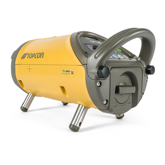
4. PRODUCT OUTLINE Parts and Functions of the Instrument Upper laser emitting window Remote control receiving window (TP-L6WGV/WAV only) Display Operating keys Handle Battery holder Lower laser emitting window Battery holder knob (TP-L6WGV/WAV only) Self-centering feet Handle fixing screw Upper laser blocking hatch (TP-L6WGV/WAV only) Blocks the upper laser beam by rotating Remote control... -
Page 14: Control Panel
4. PRODUCT OUTLINE Control panel Warning/Standby Indication LED Power key Right key Left key Down key Up key Set key/Lock key Menu mode key The illumination of the display will be ON for 30 seconds whenever anyone key is pressed. Key/LED Nomenclature Function... -
Page 15: Menu Mode
4. PRODUCT OUTLINE Menu mode Press [MENU mode] key to access "MENU" mode. In "MENU" mode, you can use the following functions. Display Menu item Function BEAM SETTING Beam setting Turn ON/OFF Upper/Lower laser and Centerline LED. "Setting ON/OFF of Upper/Lower laser and Centerline LED"... -
Page 16: How To Change Menu Items
4. PRODUCT OUTLINE How to change menu items In "MENU" mode, use [Down] key/[Up] key to access a desired menu item. MENU mode screen Basic screen MENU(1/5)*1 BEAM SETTING MENU(2/5)*1 AUTO ALIGNMENT MENU(3/5)*1 DISPLAY SETTING MENU(4/5)*1 SECURITY 1:The menu number is changed according MENU(5/5)*1 to models. -
Page 17: Indicators
4. PRODUCT OUTLINE Indicators Laser line indicator Digital level vial, rotate Indicates the direction of the instrument until centered laser line. Battery warning indication Bluetooth indication Remaining battery capacity is shown in 3 steps. The Bluetooth power supply is ON. Power remaining for Bluetooth is already connected. -
Page 18: Warning Indications
4. PRODUCT OUTLINE Warning indications Battery warning indication Operation is impossible. Replace with a fully charged battery. The laser beam is not emitted then, and the centerline LED does not turn on, too. The power is automatically turned OFF within ten minutes. Level warning indication The instrument tilted beyond the auto-leveling range to the back or front. - Page 19 4. PRODUCT OUTLINE Laser position adjusting/Reconfirmation of the grade value RETRY LASER The display will appear when the laser adjustment and reconfirmation of the SETTING grade value are necessary. WAIT • While "RETRY LASER SETTING WAIT" is displayed, the key operations are impossible.
-
Page 20: Using The Battery
5. USING THE BATTERY Be sure to charge the battery fully before using it for the first time or after not using it for long periods. • The charger will become rather hot during use. This is normal. • Do not use or charge batteries other than those designated. (Battery:BDC72 Charger:CDC77) •... -
Page 21: Installing The Battery
5. USING THE BATTERY • Slots 1 and 2: The battery charger can hold and charge up to two batteries at the same time. • Charging time per battery: BDC72: about 8 hours (at 25°C) (Charging can take longer than the times stated above when temperatures are either especially high or low.) •... - Page 22 5. USING THE BATTERY 3. As shown below, install the battery to the battery holder. 4. Attach the battery holder to the TP-L6W. 5. Attach the battery holder to the TP-L6W and turn the battery holder knob to the “LOCK” side to fix the battery holder.
-
Page 23: Basic Operation
6. BASIC OPERATION Setting up the Instrument 1. Always position the instrument so the bubble in the digital level vial is centered. • The laser might move from side to side in order to adjust the position of laser beam after the instrument is turned ON (See WAIT display on p.15). -
Page 24: Set Grade Value By Moving Laser
6. BASIC OPERATION Procedure Key operation Display 5. Press [Right] key to shift to digit B. Disit B is highlighted. 6. Press [Down] or [Up] key to change value to "2". 7. Repeat previous steps to change values of digit C to "3", digit D to "4" and digit E to "5". 8. -
Page 25: Setting Laser Line
6. BASIC OPERATION Setting Laser Line After setting the grade value, set the laser line. Use [Left] key and [Right] key to set the laser line. The maximum adjusting range is 9 m (29.5 ft.) at a distance of 30 m (100ft.) The speed of the line travel is variable. -
Page 26: Automatic Centering
6. BASIC OPERATION Automatic Centering 1. Press both [Right] and [Left] keys at the same time. The laser will return to the center of the line adjustment range automatically. • Automatic centering is not possible when the instrument is locked. Laser line indication Press the [Left ] and [Right ] key at the same time. -
Page 27: Automatic Alignment With The Target (Tp-L6Wgv/Wg/Wav/Wa Only)
6. BASIC OPERATION Automatic alignment with the target (TP-L6WGV/WG/WAV/WA only) When the alignment is placed on centerline so it is in the alignment path of the beam, the laser will search the horizontal center of the target and automatically align the beam to it. ... - Page 28 6. BASIC OPERATION The display shows auto leveling is in process. After auto leveling is completed, automatic alignment starts. WAIT The display shows auto alignment is in process. Each step shows alignment progress. Automatic alignment in progress Automatic alignment will finish soon. Alignment is completed.
-
Page 29: Setting Centerline Led/Setting Laser
6. BASIC OPERATION Setting Centerline LED/Setting Laser Setting ON/OFF of Upper/Lower laser and Centerline LED • Set ON/OFF of Upper/Lower laser. (TP-L6WGV/WAV only): "V-LD" is indicated on the screen. • Set ON/OFF of Centerline LED. (TP-L6WG/WBG/WA/WB only): "V-LED" is indicated on the screen. Factory setting : [OFF] Procedure Key operation... -
Page 30: Setting Upper/Lower Laser And Centerline Led Automatic Power Off
6. BASIC OPERATION Setting Upper/Lower laser and Centerline LED automatic power off • When you want to activate "automatic power off (after 30 minutes)" for Upper/Lower laser, set this function. (TP-L6WGV/WAV only): "V-LD" is indicated on the screen. • When you want to activate "automatic power off (after 30 minutes)" for Centerline LED, set this function. (TP-L6WG/WBG/WA/WB only): "V-LED"... -
Page 31: Changing The Laser Mode (On/Blinking/Energy-Saving)
6. BASIC OPERATION Changing the laser mode (ON/Blinking/Energy-saving) As mentioned below, the laser mode can be changed. Factory setting : " mode" TP-L6WAV/WA/WB TP-L6WGV/WG/WBG Display Mode Display Mode ON mode ON mode Blinking mode Blinking mode Energy-saving mode Procedure Key operation Display 1. -
Page 32: Setting Display Method
6. BASIC OPERATION When operating through RC-500 1. Make sure that the basic screen is indicated on the TP-L6 2. Press [Laser beam mode] key. Laser beam mode key Each time you press [Laser beam mode] key, the mode is changed as shown below. For the details of RC-500, "8.2 Remote Controller (RC-500 )"... - Page 33 6. BASIC OPERATION Procedure Key operation Display 4. Press [Right] key to highlight [OFF]. *2 DISPLAY(1/3) R-TILT DISP-1 5. Press [Set/Lock] key. Setting is set to [OFF]. * 1: Press [Menu mode] key, and the instrument returns to the “Basic screen” status. * 2: Press [Menu mode] key, and the instrument returns to the “Procedure 2”...
- Page 34 6. BASIC OPERATION Procedure Key operation Display 6. Press [Set/Lock] key. Setting is completed. * 1: Press [Menu mode] key, and the instrument returns to the “Basic screen” status. * 2: Press [Menu mode] key, and the instrument returns to the “Procedure 2” status. * 3: The menu number is changed according to models.
-
Page 35: Setting Bluetooth Connection
6. BASIC OPERATION * 1: Press [Menu mode] key, and the instrument returns to the “Basic screen” status. * 2: Press [Menu mode] key, and the instrument returns to the “Procedure 2” status. * 3: The menu number is changed according to models. Setting Bluetooth Connection To operate the TP-L6W with smartphone, it is necessary to set Bluetooth connection (pairing). -
Page 36: Performing Pairing With Smartphone
6. BASIC OPERATION Procedure Key operation Display 5. Press [Set/Lock] key. The Bluetooth power supply is ON. "Bluetooth power ON" icon * 1: Press [Menu mode] key, and the instrument returns to the “Basic screen” status. * 2: Press [Menu mode] key, and the instrument returns to the “Procedure 2” status. * 3: The menu number is changed according to models. -
Page 37: Connecting To Smartphone
6. BASIC OPERATION Procedure Key operation Display 6. Search the TP-L6W from the smartphone and perform pairing. When pairing is completed, "SET" is indicated and the basic screen appears again. • For the searching method, refer to the instruction manual of the software used in the smartphone. - Page 38 6. BASIC OPERATION Procedure Key operation Display 3. Press [Set/Lock] key. *2 BLUETOOTH(1/3) BT POWER 4. Press [Down] key twice. *2 BLUETOOTH(3/3) The Bluetooth address is displayed. (Example:0123456789AB) BT ADDRESS Twice 0123456789AB Press [Set/Lock] key again, and the basic screen appears again. In this case, if data is changed in any other item of the menu, the change is stored.
-
Page 39: Setting Security Code
7. SETTING SECURITY CODE To prevent unauthorized use of the TP-L6W a four-digit security can be set. The following table describes how to activate the security mode (S CODE) and select a four-digit code. When Security mode is set, it is necessary to input the code every time power is turned on (in Normal mode, Selecting mode and Checking &... -
Page 40: Setting On/Off Of Security Mode
7. SETTING SECURITY CODE Procedure Key operation Display 9. Press [Set/Lock] key. *1: When security code has been entered, but security mode is OFF, input of current security code is necessary to change security code. *2: After all four digits are chosen and the [Set/Lock] key is pressed, each digit will highlight in sequence. While it is higlighting, it is possible to change the number in case of error. -
Page 41: Changing Security Code
7. SETTING SECURITY CODE Changing Security Code Example: Change security code to "5246". Procedure Key operation Display 1. Press [Menu mode] key. MENU(1/5) BEAM SETTING 2. Press [Down] key three times. MENU(4/5) SECURITY Three times 3. Press [Set/Lock] key. SECURITY(1/3) S CODE 4. -
Page 42: Changing Company Name
7. SETTING SECURITY CODE Procedure Key operation Display 10.Press [Set/Lock] key. * 1: The menu number is changed according to models. Changing Company Name The company name displayed during power-up can be changed. The following characters can be used: Numeric digits 0 to 9; capital letters A to Z; period; comma; apostrophe; space; opened and closed parenthesis. Maximum of 32 characters can be input (2 lines of 16 characters each). - Page 43 Procedure Key operation Display 6. Select a character string by pressing [Up] =_ _ TOPCON _ _ _ or [Down] keys. _ _ _ _ _ _ _ _ _ ABCDEFGHIJ←→ENT 7. Select a character in the character string by =_ _ TOPCON _ _ _ pressing [Right] or [Left] keys.
- Page 44 7. SETTING SECURITY CODE ■ How to correct a character Procedure Key operation Display 1. Select the left or right arrow by pressing the ˍˍˍˍˍˍˍ LASOR(1) [Left] or [Right] keys. ˍˍˍˍˍˍˍˍˍˍˍˍˍˍ ()01234567 ←→ENT 2. Press [Set/Lock] key. ˍˍˍˍˍˍˍ LASOR(1) The underline (cursor) moves to left or right ˍˍˍˍˍˍˍˍˍˍˍˍˍˍ...
-
Page 45: Standard Accessories
8. STANDARD ACCESSORIES Self-centering Feet Four sets of centering feet are provided with the TP-L6W. The feet provided with TP-L6W will center the laser beam inside the following diameters of pipe: 150mm (6"), 200mm (8"), 250mm (10") and 300mm (12") They can also be used to set laser on top of the pipe or on a flat surface. -
Page 46: Remote Controller (Rc-500 )
8. STANDARD ACCESSORIES Remote Controller (RC-500 ) The RC-500 allows you to remotely control most function of the TP-L6 as shown below. The RC-500 is convenient for aligning the beam while using a transit, or for saving power by temporarily putting the unit in standby mode using the ON/OFF switch. -
Page 47: Replacing Battery For Remote Controller Rc-500
8. STANDARD ACCESSORIES • When using the remote controller, direct the signal aperture to the remote control receiving window on front of the TP-L6W. Remote control receiving window Remote control receiving window (Laser beam can be received from above panel.) Laser line will travel in the opposite Laser line will travel in the direction of the laser right/left key... -
Page 48: Target
8. STANDARD ACCESSORIES Target Select the size of target assembly appropriate for the pipe diameter. Target (L) Detection strips Fixing screw (TP-L6WGV/WG/WAV/WA only) Level vial Laser receiving side Target holder Target (S) -
Page 49: Checks And Adjustments
9. CHECKS AND ADJUSTMENTS Procedure To Check and Adjust Laser Calibration +00.000% Checking Calibration 1. Make sure grade is set to 00.000% (0‰). 2. Locate control points directly beneath the laser beam 1m (3.3 ft) in front of the W and 60m TP-L6 (197ft.) from the first control point (see illustration above). - Page 50 9. CHECKS AND ADJUSTMENTS Procedure Key operation Display 4. Adjust the height of laser beam x1 and X2 measurements are equal (use [ ] or Down LEVEL [Up] key). • The display will be changed to "LEVELING" again if the instrument is moved. In this case, wait until the display changes to "LEVEL"...
-
Page 51: Checking Of Upper/Lower Laser (Tp-L6Wgv/Wav Only)
9. CHECKS AND ADJUSTMENTS Checking of Upper/Lower Laser (TP-L6WGV/WAV only) 1. Set up the instrument on a single control point using the lower laser. 2. Set up a target approximately 3m (10ft.) above the instrument. 3. Move the target above the manhole unit the upper laser is aligned to the center of the target. 4. -
Page 52: Error Displays
Set the instrument level then repeat during calibration checking or adjusting. checking and adjusting calibration procedure. Abnormal operation of internal memory Switch OFF the power, then ON E-99 system detected. again. • If error code remains after trying countermeasures above, please contact your Topcon dealer. -
Page 53: Troubleshooting
11.TROUBLESHOOTING Check to see the instrument referring to the error list or the following troubleshooting list when you notice the failure of the instrument. If the instrument can't be recovered or the failure isn't written in the following list, please contact your local dealer. - Page 54 11. TROUBLESHOOTING Conditions Causes Countermeasures The grade setting 1) Incorrect grade value was entered. 1) Confirm the input value ( or %) ‰ value of the TP-L6W and reset. and the measured 2) The bubble on the bubble tube 2) Adjust the laser and/or target so grade value are not display of the instrument or the the bubble is centered.
-
Page 55: Optional Accessories
12.OPTIONAL ACCESSORIES • Battery holder DB-81 • Drop manhole kit model 6 • Single point foot model 2 • Trivet stand model 4 • Trivet handle model 2 • Tripod adapter model 3 • Scope model 2 • Over the top target ... -
Page 56: Specifications
13.SPECIFICATIONS TP-L6 series Light source Visible laser diode Wave length 520nm (TP-L6WGV/WG/WBG, green) 635nm (TP-L6WAV/WA/WB, red) Laser power output 4.5mW (CW) Laser class Class 3R Laser diameter ø12mm (collimated) (The laser relating specifications described above apply to the internal laser as well.) Line control width Approx. - Page 57 13. SPECIFICATIONS • Battery using time will vary depending on environmental conditions and operations done with TP-L6W series. Charger (CDC77) Input voltage 100 to 240 V AC Charging time (at 25°C per battery) BDC72 About 8 hours (Charging may take longer than this at low or high temperature.) Range of charging temperature 0 to 40°C (32 to 104 °F)
-
Page 58: Regulations
14.REGULATIONS Region/ Directives/ Labels/Declarations Country Regulations FCC Compliance WARNING: Changes or modifications to this unit not expressly approved by the party responsible for compliance could void the user's authority to operate the equipment. NOTE: This equipment has been tested and found to comply with limits for a Class B digital device, pursuant to Part 15 of the FCC Rules. - Page 59 14. REGULATIONS Region/ Directives/ Labels/Declarations Country Regulations California, Recycling and NY, Batteries U.S.A. This class B digital apparatus meets all requirements of Canadian interference-Causing Equipment Regulations. Cet appareil num rique de la class B respecte toutes les exigences du é glement sur le mat rique brouilleur du Canada.
- Page 60 In industrial locations or in proximity to industrial power installations, this instrument might be affected by electromagnetic noise. Under such conditions, please test the instrument performance before use. Hereby, TOPCON CORPORATION declares that the radio equipment type of this product is in compliance with Directive 2014/53/EU. EMC-Class B EU declaration of conformity is available depending on your request.
- Page 61 Please see the following website for contact addresses. GLOBAL GATEWAY https://global.topcon.com © 2020 TOPCON CORPORATION ALL RIGHTS RESERVED...
Need help?
Do you have a question about the TP-L6 Series and is the answer not in the manual?
Questions and answers
If I lost the rc500 can I get a replacement and connect to my laser
The manual mentions that optional accessories, which may include the RC-500 remote control, are sold separately and may be subject to change or discontinuation without notice. It advises contacting a local dealer for details.
This answer is automatically generated