
Related Manuals for Topcon RM-8800


Summary of Contents for Topcon RM-8800
- Page 1 Заказывайте у нас на сайте www.euromed.in.ua INSTRUCTION MANUAL AUTO REFRACTOMETER RM-8800 AUTO KERATO-REFRACTOMETER KR-8800...
-
Page 3: Introduction
INTRODUCTION Thank you for purchasing the Auto Refractometer RM -8800, Auto Kerato-Refractometer KR-8800. This instrument is used to measure the spherical refractive-power,cylindrical refractive power, the direction of astigmatic axis, the radius of curvature, the direction of principal meridian and the cor- neal refractory power. -
Page 4: Precautions
PRECAUTIONS BASIC INSTRUCTIONS To prevent your fingers from getting caught in the instrument, be aware of all moving parts. WORKING ENVIRONMENT Temperature: 10°C-40°C Humidity: 30-75% (without dew) Atmospheric Pressure: 700hPa-1,060hPa STORAGE METHOD 1. ENVIRONMENTAL CONDITIONS Temperature: 10 °C-40 °C Humidity: 30-75% (without dew) Atmospheric Pressure: 700hPa-1,060hPa... -
Page 5: Safety Displays
SAFETY DISPLAYS In order to encourage the safe use of the instrument and to avoid danger to the operator and oth- ers as well as damage to properties, warnings are described in the Instruction Manual and marked on the instrument body. We suggest you thoroughly understand the meaning of the following displays/icons and Safety Cautions, as well as read the Manual, and strictly observe the instructions. -
Page 6: Safety Cautions
SAFETY CAUTIONS WARNINGS Icon Meaning Page To avoid electric shocks, do not attempt overhauling, rebuilding or repairs. Ask your dealer for repair. To avoid electric shocks, do not remove covers from bottom and top surfaces, monitor, measuring unit, etc. To prevent shock hazard, do not allow water or other foreign matter ––... - Page 7 SAFETY CAUTIONS CAUTIONS Icon Meaning Page Before moving the instrument, fasten the clamping knob at the bot- tom surface to stop movements. Negligence of this may cause injury by falling parts. When moving the instrument, be sure to hold it at the bottom sur- face with two persons.
-
Page 8: Usage And Maintenance
For details, See “CLEANING THE INSTRUMENT” on page 81. ESCAPE CLAUSES • TOPCON shall not take any responsibility for damage due to fire, earthquakes, actions by third persons and other accidents, or the negligence and misuse of the user and use under unusual conditions. -
Page 9: Warning Indications And Positions
To secure safety, this equipment provides warnings. Correctly use the equipment following these warning instructions. If any of the following mark- ing labels are missing, please contact your dealer or TOPCON to the address stated on the back cover. CAUTION •... -
Page 10: Table Of Contents
CONTENTS INTRODUCTION ..................1 PRECAUTIONS..................2 WORKING ENVIRONMENT..............2 STORAGE METHOD.................2 TRANSPORT CONDITION ...............2 SAFETY DISPLAYS ..................3 SAFETY CAUTIONS .................4 USAGE AND MAINTENANCE ..............6 USER MAINTENANCE................6 ESCAPE CLAUSES ..................6 WARNING INDICATIONS AND POSITIONS ..........7 COMPONENT NAMES MAIN BODY COMPONENTS..............10 CONTROL PANEL COMPONENTS............11 MONITOR SCREEN................13 PRINTER OUTPUT .................15 STANDARD ACCESSORIES ..............18 PREPARATIONS... - Page 11 SPECIFICATIONS AND PERFORMANCE .........................77 ELECTROMAGNETIC COMPATIBILITY ..........79 ELECTRIC RATING ................79 SYSTEM CLASSIFICATION ..............79 PURPOSES OF USE ................79 REFERENCE OPTIONAL ACCESSORIES..............80 SHAPE OF PLUG..................80 MAINTENANCE DAILY CHECKUPS .................81 MAINTENANCE..................84...
-
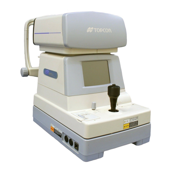
Page 12: Component Names
COMPONENT NAMES MAIN BODY COMPONENTS Measuring Head Unit Measuring Head monitor Measurement switch Contorol lever Clamping knob Base Unit Control panel Power lampw Clamping knob (for movement) External I/O terminal Chinrest Unit Forehead rest Examination window Eye height mark Brightness volume Chinrest tissue pin Chinrest Power switch... -
Page 13: Control Panel Components
CONTROL PANEL COMPONENTS RM-8800 Print switch Menu switch IOL switch Graphic print switch Target image observation switch Fixation target brightness switch CYL (cylinder) display selection switch Print switch........Prints out the measurement result. When there is no measurement value, press the switch to feed paper. - Page 14 KR-8800 Print switch Menu switch Graphic print switch Auto start switch Target image observation switch IOL switch Fixation target brightness switch CYL (cylinder) Measurement display selection mode switch switch Cornea diameter switch Print switch......Prints out the measurement result. When there is no mea- surement value, press the switch to feed paper.
-
Page 15: Monitor Screen
MONITOR SCREE When unreliable,the IOL m ode m ark blinks. Заказывайте у нас на сайте RM-8800 www.euromed.in.ua MEASURING SCREEN (LAYOUT 1) Result of refractory power Result of refractory power measurement (Right eye) measurement (Left eye) Alignment mark Smallest measurable pupil Instrument No. - Page 16 Заказывайте у нас на сайте www.euromed.in.ua KR-8800 MEASURING SCREEN(LAYOUT 1) Result of refractory power Result of refractory power measurement (Left eye) measurement (Right eye) S + 0.00 + 0.00 + 0.50 + 0.50 C Cornea measurement result(Left Cornea measurement eye) 43.00 43.00 44.00...
-
Page 17: Printer Output
Заказывайте у нас на PRINTER OUTPUT сайте RM-8800 www.euromed.in.ua Bar code Work ID No. -RM 010602- NAME Patient No. Instrument No. 2003_ 03_01 AM 10 : 00 VD (vertical distance) N o . 0 0 0 1 Cylindrical power mark VD : 12.00... - Page 18 ■4■ 43.75 44.50 Low reliability mark TOPCON ALL mode (example) When measurement is done under the IOL mode, a reliability factor is printed out following the Ι mark. The reliability factor is formed with integers 1 to 9 in increasing order of reliability.
- Page 19 Typical value of left eye -0.25 -0.75 -0.25 Measured value of left eye S.E. -0.75 CORNEA DIA : 12.00 PD (pupil distance) PD : 65 ADD : 2.25NPD : 61 TOPCON ■1■ 7.50 7.53 ■2■ 7.50 7.53 ■3■ 7.50 7.53 ■4■ 7.50 7.53...
-
Page 20: Standard Accessories
STANDARD ACCESSORIES The following are standard accessories. Make sure that all these items are included (quantity). Power cable (1) Chinrest pin (2) Printer paper (2) Silicon cloth (1) Chinrest tissue (1) Dust cover (1) Fuse (2) Instruction manuals: unpacking and assembling (1 each) Accessory box (1) Model eye (1) COMPONENT NAMES... -
Page 21: Preparations
PREPARATIONS INSTALLATION Before moving the instrument, fasten the clamping knob at the bottom surface to stop movements. Negligence of this may CAUTION cause injury by falling parts. When moving the instrument, be sure to hold it at the bottom surface with two persons. Carrying by one person may cause a backache or injury by falling parts. -
Page 22: Connecting Power Cable
CONNECTING POWER CABLE Be sure to connect the power plug to an AC 3-pin receptacle equipped with grounding. Connection with receptacle without WARNING grounding may cause fire and electric shock in case of short- circuiting. To avoid electric shocks, do not handle the power plug CAUTION with wet fingers. -
Page 23: Initial Settings
INITIAL SETTINGS In the initial setting, settings such as patient No., instrument No., refractory power shift, ON LINE, auto print, etc. can be done. PREPARATION FOR INITIAL SETTING Make sure of the connection of power cable. For connection, see “CONNECTING POWER CABLE” on page 20. While pressing of the control panel, press on the MENU SWITCH... -
Page 24: Initial Set Screen
Заказывайте у нас на INITIAL SET SCREEN сайте www.euromed.in.ua In the INITIAL SET screen, buzzer sound, refractory power shift, display of typical value in monitor screen and date can be changed. In the “INITIAL MENU SCREEN”, make sure that the cursor is on “INITIAL SET”, and then press the . - Page 25 SHIFTING REFRACTORY POWER The refractory power (S value) can be shifted. In the “INITIAL MENU SCREEN”, choose “INITIAL SET” and get the “INITIAL SET” screen. Заказывайте у I N I T I A L S E T BUZZER DPTR SHIFT +0.37 нас...
- Page 26 CHANGING DATE DISPLAY The date format of printout can be changed. Before shipment, it is set to “2003.12.01”. In the “INITIAL MENU SCREEN”, choose “INITIAL SET” and get the “INITIAL SET SCREEN”. I N I T I A L S E T BUZZER DPTR SHIFT 2003.12.01...
- Page 27 CHANGING THE CORNEA DIAMETER MEASUREMENT METHOD (Only in KR-8800) The method of cornea diameter measurement can be chosen between the measurement using the actual image or the static image. Before shipment, the setting is NO (measurement using actual image). Press the and bring the cursor to C.D MEMORY.
- Page 28 ADD FACTOR The ordinary additional power (ADD) can be printed out. Before shipment, it is set to [NO] (no printout). In the “INITIAL MENU SCREEN”, choose “INITIAL SET” and get the “INITIAL SET SCREEN”. I N I T I A L S E T DPTR SHIFT AVERAGE DISP.
-
Page 29: No. Setting
NO. SETTING In the “NUMBER SET” screen, patient No. setting, monitor screen display of patient No., printing patient No., resetting of patient No., instrument No. setting, monitor screen display of instrument No. and printing instrument No. can be changed. In the “INITIAL MENU SCREEN”, press the and move the cursor MEASUREMENT SWITCH to “NUMBER SET”. - Page 30 MONITOR SCREEN DISPLAY OF PATIENT NO. The patient No. can be displayed in the monitor screen. Before shipment, it is set to (YES). In the “INITIAL MENU SCREEN”, choose “NUMBER SET” and get the “NUMBER SET SCREEN”. N U M B E R S E T SERIAL NO.
- Page 31 RESETTING PATIENT NO. The patient No. can be reset by switching on the power source. Before shipment, it is set to “NO” (no reset). In the “INITIAL MENU SCREEN”, choose “NUMBER SET” and get the “NUMBER SET SCREEN”. N U M B E R S E T SERIAL NO.
- Page 32 MONITOR SCREEN DISPLAY OF INSTRUMENT NO. The instrument No. can be displayed in the monitor screen. Before shipment, it is set to “NO” (no display). In the “INITIAL MENU SCREEN”, choose “NUMBER SET” and get the “NUMBER SET SCREEN”. N U M B E R S E T SERIAL NO.
-
Page 33: Printout
PRINTOUT In the “PRINT OUT” screen, printout format, printing equivalent spherical power, printing computer lensmeter data, and printing bar code can be changed. In the “INITIAL MENU SCREEN”, press the and move the cursor MEASUREMENT SWITCH to “PRINT OUT”. Press the , and the monitor screen is changed to the “PRINT OUT PRINT SWITCH SCREEN”. - Page 34 PRINTING EQUIVALENT SPHERICAL POWER The equivalent spherical power can be printed. Before shipment, it is set to “YES” (printout). In the “INITIAL MENU SCREEN”, choose “PRINT OUT” and get the “PRINT OUT SCREEN”. P R I N T O U T PRINT TYPE S.E.
- Page 35 PRINTING BAR CODE The bar code can be printed out. Before shipment, it is set to “NO” (no printout). In the “INITIAL MENU SCREEN”, choose “PRINT OUT” and get the “PRINT OUT SCREEN”. P R I N T O U T PRINT TYPE S.E.
- Page 36 CHANGING THE PRINTOUT DISPLAY ORDER (Only in KR-8800) Press the and bring the cursor to “DATA ORDER”. MEASUREMENT SWITCH The printout display order of cornea refractory power and curvature can be changed. Before shipment, the setting is “D/MM”. P R I N T O U T PRINT TYPE S.E.
-
Page 37: Custom-Print Settings
On the custom-print screen, the details of the following items can be changed individually: refraction measurement values, cornea measurement values, corneal astigmatism and axial angles, PD values, the name, date, VD values, cylindricity mark and the TOPCON mark On/Off. On the “PRINT OUT SCREEN”, press the and move the cursor to MENU SWITCH “PRINT TYPE”. - Page 38 CHANGING THE PRINT TYPE OF REFRACTION MEASUREMENT VALUES The print type of refraction measurement values may be changed. Before shipment it is set to “ALL” (print all data). On the “PRINT OUT SCREEN”, move the cursor to “PRINT TYPE”, and with “CSTM” selected, press the and get the “CSTM PRINT SCREEN ”.
- Page 39 PRINTING AVERAGE VALUES OF CORNEA MEASUREMENTS (Only in KR-8800) Average values of cornea measurements may be printed out. Before shipment it is set to “YES” (print average values). On the “PRINT OUT SCREEN”, move the cursor to “PRINT TYPE”, and with “CSTM” selected, press the and get the “CSTM PRINT SCREEN”.
- Page 40 PRINTING PD VALUES PD values may be printed out. Before shipment it is set to “YES” (print PD values). On the “PRINT OUT SCREEN”, move the cursor to “PRINT TYPE”, and with “CSTM” selected, press the and get the “CSTM PRINT SCREEN”. IOL SWITCH C S T M P R I N T REF PRINT...
- Page 41 PRINTING THE DATE The date may be printed out. Before shipment it is set to “YES” (print date). On the “PRINT OUT SCREEN”, move the cursor to “PRINT TYPE”, and with “CSTM” selected, press the and get the “CSTM PRINT SCREEN”. IOL SWITCH C S T M P R I N T KRT PRINT...
- Page 42 , and the cursor moves to the next item. MEASUREMENT SWITCH PRINTING THE TOPCON MARK The TOPCON mark may be printed out. Before shipment it is set to “YES” (print TOPCON mark). On the “PRINT OUT SCREEN”, move the cursor to “PRINT TYPE”, and with “CSTM”...
-
Page 43: On-Line (Data Communication)
ON-LINE (DATA COMMUNICATION) In the “ON-LINE” screen, computer lensmeter data receiving format, communication format and communication speed can be changed. In the “INITIAL MENU SCREEN”, press the and move the cursor MEASUREMENT SWITCH to “ON-LINE”. Press the , and the monitor screen is changed to the “ON-LINE SCREEN”. PRINT SWITCH O N - L I N E CL INPUT... - Page 44 , and the cursor moves to the next item. MEASUREMENT SWITCH SETTING COMMUNICATION FORMAT The communication format can be set. Before shipment, it is set to “OLD” (old TOPCON format). In the “INITIAL MENU SCREEN”, choose “ON-LINE” and get the “ON-LINE SCREEN”.
- Page 45 ,and the cursor moves to the next item. MEASUREMENT SWITCH For inquiries about the RS232C communication format, please contact your dealer or Topcon at the address stated on the back cover. SELECTING RS232C OUTPUT DATA (Only in KR-8800) Press the and bring the cursor to “OUTPUT DATA TYPE”s.
-
Page 46: Menu Setting
Заказывайте у нас на сайте MENU SETTING www.euromed.in.ua In menu setting, data step, contact/glasses, continuous measurement, RS232C, date and time can be set. PREPARATION FOR MENU SETTING Make sure of the connection of power cable. For connection, see “CONNECTING POWER CABLE” on page 20. Press “ON”... - Page 47 SETTING STEP The measurement step can be selected from 0.12, 0.25. Before shipment, it is set to “0.25”. Press the of the control panel and get the “SETTING MENU SCREEN”. MENU SWITCH “STEP” is inverted, and measurement steps are displayed on the right with the set step inverted.
- Page 48 SETTING VD In VD setting, contact (0) or glasses (12mm or 13.75mm) can be selected. Before shipment, it is set to glasses (12mm). Press the of the control panel and get the “SETTING MENU SCREEN”. MENU SWITCH Press the and invert “VD”. MEASUREMENT SWITCH VD figures are displayed on the right.
- Page 49 SETTING OUTPUT DATA The RS232C output can be set. Before shipment, it is set to “NO” (no output). Press the of the control panel and get the “SETTING MENU SCREEN”. MENU SWITCH Press the and invert “OUTPUT DATA”. MEASUREMENT SWITCH “YES”...
- Page 50 SETTING DATE/TIME Press the of the control panel and get the “SETTING MENU SCREEN”. MENU SWITCH Press the and invert “DATE/TIME”. MEASUREMENT SWITCH The date/time is displayed on the right. Press the and invert the desired item. PRINT SWITCH Change figures by pressing the (increase) or (decrease).
- Page 51 SETTING HV/R1R2 (Only in KR-8800) You can select how the cornea measurement is displayed on the monitor screen from either HV (horizontal/vertical direction) or R1R2 (radius of curvature of strong/weak principal meridian). When shipped, the HV(horizontal/vertical direction) is selected as the default setting.
-
Page 52: Printer Paper Setting
PRINTER PAPER SETTING AUTO SETTING • Note that printing cannot be done if the paper back faces up by set- NOTE: ting the roll in opposite direction. • Please insert the paper deep enough into the printer. NOTE: otherwise the paper may not come out. At this time “PAPER END” will be displayed on the monitor. - Page 53 Turn the paper roll backward to remove any sag. Feed the paper with your finger. Reset the paper retainer lever to the original upright position. While pressing the paper to the printer, press the continuously until it is PRINT SWITCH inserted deep enough and fed forward.
- Page 54 After making sure that the paper comes out, attach the printer cover. Please insert the printer cover until it clicks. A 58mm wide paper roll (example: TF50KS-E2C [Nippon Paper Co.]) is recom- mended. Other paper rolls may cause unnecessarily large printing noise or unclean printing. PREPARATIONS...
- Page 55 MANUAL SETTING While pressing the thumb to the surface, slide off the printer cover. Set the paper into the shaft support, taking care of the roll direction of paper. Pull out the paper top 7-8cm forward. Rotate the paper retainer lever in the arrow direction. Paper retainer lever Set the paper retainer lever at the illustrated position where it becomes a little heavier.
- Page 56 Insert the paper into the printer straight along the paper guide. Turn the paper roll backward to remove any sag. Feed the paper with your finger. Insert the paper further until the paper top comes out from the outlet. If the paper retainer lever is not set to the proper position or if the paper is not cut on the control lever side, the paper does not go smoothly into the printer.
- Page 57 Align the paper so that it comes out straight and then lower the paper retainer lever to the level position. Attach the printer cover so that the paper comes outside. Please insert the printer cover until it clicks. The paper retainer lever can be set in 2 steps. If a paper jam occurs, fully rotate the paper retainer lever to the illustrated position, and remove the stuffed paper pieces from the printer.
-
Page 58: Resetting From Power Save Status
RESETTING FROM POWER SAVE STATUS This instrument adopts the power save system for saving electric power. Namely, when the main body is not in operation, power supply to the monitor and CCD camera is stopped. Under the power-save condition, only the POWER lamp of control panel lights and the monitor screen is off. -
Page 59: Basic Operations
BASIC OPERATIONS PREPARATION BEFORE MEASUREMENT APPLYING POWER SOURCE Make sure of the connection of power cable. For connection, see “CONNECTING POWER CABLE” on page 20. Press on the POWER SWITCH Confirm that the title screen is displayed and then the measurement screen is displayed in a few seconds. - Page 60 Adjust the chinrest height so that the patient's eye becomes level with the eye height mark. Eye height mark BASIC OPERATIONS...
-
Page 61: Measurement Under Auto Start Mode (Only In Kr-8800)
MEASUREMENT UNDER AUTO START MODE (ONLY IN KR-8800) • Adjust the height of automatic instrument table so that the patient NOTICE can sit on the chair with comfort to obtain correct measurement values. POSITIONING THE PATIENT In the initial status after power on, the mode is set to the auto start. Make sure of the measurement screen. - Page 62 COLLIMATION AND MEASUREMENT (ADJUSTING THE PATIENT'S EYE TO AUTO REFRACTOMETER) Alignment operations are done with the control lever. Movement operations of the main body using the control lever. • The main body position can be fine-adjusted laterally by inclining the control lever to each direction.
- Page 63 Hold the control lever and move the main body to the operator side. Operate the control lever laterally and vertically to obtain the target eye in the center of monitor screen. R 01 01 R 01 01 0001 0001 01 01 01 01 12.00 12.00...
- Page 64 Keeping the luminous point within the alignment mark, slowly move the main body toward the patient. When the main body approaches the target eye, the alignment bar of the monitor screen changes to arrows. Minimum pupil diameter R 01 01 R 01 01 0001 0001...
- Page 65 After the alignment bar is displayed, move the main body slowly towards the patient. Measurement is done and the measurement value is displayed on the monitor screen. + 0.00 + 0.00 + 0.00 + 0.00 + 0.50 + 0.50 + 0.50 + 0.50 43.00 43.00...
-
Page 66: Measurement Under Manual Mode
MEASUREMENT UNDER MANUAL MODE • Adjust the height of automatic instrument table so that the patient NOTICE can sit on the chair comfortably to obtain accurate measurement values. SETTING THE PICTURING MODE In the initial status after power on, the mode is set to the auto start. Check of the measurement screen. - Page 67 Operate the control lever laterally and vertically so as to obtain the target eye in the center of monitor screen. Luminous point Alignment mark R 01 01 R 01 01 0001 0001 01 01 01 01 12.00 12.00 While moving the main body toward the patient, focus the target eye. A vague, reflected luminous point for alignment appears on the cornea.
-
Page 68: Erasing Measurement Values
ERASING MEASUREMENT VALUES While pressing the of the control panel, press the . All MENU SWITCH PRINT SWITCH measurement values, both right and left eyes are cleared, and the system returns to the initial status after power on. Menu switch Print switch BASIC OPERATIONS... -
Page 69: Individual Operations
INDIVIDUAL OPERATIONS PRINT-OUT OF MEASUREMENT VALUES • To avoid paper jam in the printer, do not feed the paper if it is partly cut/torn or wrinkled. • To avoid discoloring the printing paper (particularly the recording area) during storage, use a polypropylene holder and not one con- taining plasticizer (PVC, etc.). - Page 70 To cut the paper, hold the top left corner and pull it diagonally, as illustrated. • Irregular cutting may cause paper jam. NOTICE Cut the paper cleanly. INDIVIDUAL OPERATIONS...
-
Page 71: Measurement Of Cornea Diameter (Only In Kr-8800)
MEASUREMENT OF CORNEA DIAMETER (ONLY IN KR-8800) For the measurement of cornea diameter, “C.D MEMORY YES” (measurement of static image) or “C.D MEMORY NO” (measurement of dynamic image) can be selected in the initial setting. For changing settings, see “Changing the cornea diameter measurement method (Only in KR- 8800)”... - Page 72 Bring the left positioning bar to the left end of iris by pressing the (for AUTO START SWITCH moving left) and (for moving right). TARGET IMAGE SWITCH CORNEA DIAMETER Press the MEASUREMENT SWITCH The guide mark moves right. Bring the right positioning bar to the right end of iris by pressing the AUTO START SWITCH (for moving left) and (for moving right).
- Page 73 • To get out of the mode during measurement, press the PRINT SWITCH • When the measurement result is necessary for one eye only, do the measure- ment and then press the and get out of the mode. PRINT SWITCH •...
- Page 74 Store the image of left eye in like manner. CORNEA DIAMETER (Measuring the left eye only) Press the CORNEA DIAMETER SWITCH Make sure of the cornea diameter screen. Bring the left positioning bar to the left end of iris by pressing the (for AUTO START SWITCH moving left) and...
-
Page 75: Measurement Of Hard Contact Lens
MEASUREMENT OF HARD CONTACT LENS Make sure the unit is in the corneal curvature measurement (R/K or KRT) mode. If not, choose the R/K or KRT mode by the MEASUREMENT MODE SWITCH Fill the concave part at the top of contact lens holder of model eye with water, and paste the contact lens. -
Page 76: Input/Output Using Rs232C
INPUT/OUTPUT USING RS232C OUTPUT USING RS232C This instrument can output data to PC and the like via the RS232C interface. Make sure of the connection to RS232C OUT. For connection, see “CONNECTING EXTERNAL I/O TERMINALS” on page 20. Make sure of data communication settings. For data communication settings, see “ON-LINE (DATA COMMUNICATION)”... -
Page 77: Troubleshooting
TROUBLESHOOTING TROUBLE-SHOOTING OPERATIONS MESSAGES GIVEN DURING MEASUREMENT “OVER-SPH” Spherical power exceeds +22D or -25D. “OVER-CYL” Cylindrical power exceeds ±10D. “OVER-R” Indicates that the corneal curvature exceeds 5.00-10.00mm. “NO TARGET” This indicates there is no target eye or the eye image is too dark. “AGAIN”... - Page 78 If a trouble is suspected, check conditions following the check list shown below. If the disposition according to the given instructions does not improve the condition, or if there is no relevant check item in the list, contact your dealer or TOPCON to the address stated on the back cover.
-
Page 79: Specifications And Performance
SPECIFICATIONS AND PERFORMANCE RM -8 8 00 Measuring range Hyperopia: 0 to +22D 0.25D step display (switchable to 0.12D step display) Myopia: 0 to -25D 0.25D step display (switchable to 0.12D step display) Astigmatism: 0 to 10D 0.25D step display (switchable to 0.12D step display) Axial angle: 0 to 180°... - Page 80 K R-8 8 00 Measuring range Hyperopia: 0 to +22D 0.25D step display (switchable to 0.12D step display) Myopia: 0 to -25D 0.25D step display (switchable to 0.12D step display) Astigmatism: 0 to 10D 0.25D step display (switchable to 0.12D step display) Axial angle: 0 to 180°...
-
Page 81: Electromagnetic Compatibility
SYSTEM CLASSIFICATION • Degree of protection against harmful ingress of water: IPx0 RM-8800 and KR-8800 has no protection against ingress of water. (The degree of protec- tion against harmful ingress of water defined in IEC 60529 is IPx0) • Classification according to the method(s) of sterilization or disinfection recommended by the manufacturer: not applicable. -
Page 82: Reference
REFERENCE OPTIONAL ACCESSORIES • Automatic instrument table AIT-15 The table height can readily be adjusted to facilitate measurement. Specifications • Dimensions ....510(W)x450(D)mm • Table height....600~820mm • Table size ....490x500mm • Weight .......approx. 23kg • Power consumption...270VA (100-120V,220-240V) • RS232C on-line cable SHAPE OF PLUG Country Voltage/frequency... -
Page 83: Maintenance
• When not in use, turn off the POWER switch. ORDERING CONSUMABLE ITEMS • When ordering consumable items, tell the product name, product code and quantity to your dealer or TOPCON to the address stated on the back cover. Product name Product code... - Page 84 ADJUSTING THE MONITOR SCREEN • Though this instrument is properly adjusted before shipment, sometimes screen adjustment is required due to vibrations during transportation. • To adjust contrast and brightness, turn volumes fully clockwise, viewed from the operator side, and then adjust each properly. BRIGHT PRINTER PAPER JAM •...
- Page 85 FUSE CHANGE To avoid electric shocks during fuse change, be sure to unplug the power cable before removing the fuse lid. WARNING Also, do not plug the power cable leaving the fuse box open. Always use the attached fuse (T-3A,250V). Using any other WARNING type may cause troubles and fire.
-
Page 86: Maintenance
MAINTENANCE CLEANING THE DUST COVER • Avoid cleaning plastic parts with solvents. Benzine, thinner, ether NOTICE an gasoline may cause discoloring and decomposition. If the dust cover, control panel, etc. get soiled, wipe the surface with dry cloth. If the dust cover is noticeably stained, wipe the surface with a cloth which is moistened in a tepid water solution of neutral detergent for food and then squeezed out. - Page 87 When calling please have ready the following information about your unit: • Machine type: RM-8800,KR-8800 • Manufacturing No. (Shown on the rating plate on the right side of the base.) • Period of Usage (Please give us the date of purchase).
- Page 88 Topcon House,Kennet Side,Bone Lane,Newbury,Berkshire RG14 5PX United Kingdom Phone:01635-551120 Fax:01635-551170 TOPCON SOUTH ASIA PTE.LTD. Blk 192 Pandan Loop, #07-01 Pantech Industrial Complex, SINGAPORE 128381 Phone:62780222 Fax:62733540 www.topcon.com.sg TOPCON INSTRUMENTS ( MALAYSIA ) SDN.BHD. Excella Business Park Block C,1st Floor,Jalan Ampang Putra,Taman Ampang Hillir, 55100 Kuala Lumpur,MALAYSIA Phone:03-42701192 Fax:03-42704508 TOPCON INSTRUMENTS ( THAILAND ) CO.,LTD.
Need help?
Do you have a question about the RM-8800 and is the answer not in the manual?
Questions and answers
How to solve no target issue, in my topcon rm 800 b