Table of Contents
Advertisement
Quick Links
Advertisement
Table of Contents

Related Manuals for Topcon KR-1W


Summary of Contents for Topcon KR-1W
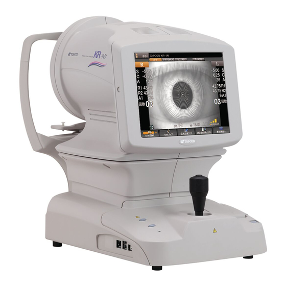
- Page 1 USER MANUAL WAVE-FRONT ANALYZER KR-1W...
-
Page 3: Introduction
• Auto alignment and auto start functions enabling quick measurement under best conditions This text outlines the TOPCON Wave-front Analyzer KR-1W and describes basic opera- tions, troubleshooting, checking, maintenance and cleaning. To encourage the safe, efficient use of this instrument, carefully read "DISPLAYS FOR SAFE USE"... - Page 4 (4) Do not store the instrument where chemicals are stored or gas is generated. 2. Normal life span of the instrument: 8 years from delivery providing regular maintenance is performed [TOPCON data] USER MAINTENANCE 1. Regularly maintain and check the equipment and parts.
-
Page 5: How To Read This Manual
HOW TO READ THIS MANUAL • Read the instructions on pages 1 to 8 before using the machine. • Regarding connection to various devices, see "PREPARATIONS" on page 30. • If you need to see how the machine works first of all, read "BASIC OPERATIONS"(page 37) first. -
Page 6: Displays For Safe Use
DISPLAYS FOR SAFE USE In order to encourage the safe use of the machine and prevent any danger to the operator and others or damage to properties, important warnings are placed on the product and inserted in the user manual. We suggest that everyone understand the meaning of the following displays and icons before reading the "GENERAL SAFETY INFORMATION"... -
Page 7: General Safety Information
When operating the instrument, be not touch the patient's eye or nose. [Inform the patient accordingly] The safety and effectiveness of the Wave-front Analyzer KR-1W has not been established for use of the device as an accessory interfaced to the refractive laser for the treatments of the higher order aberrations of the eye by photorefractive keratectomy (PRK), phototherapeutic keratectomy (PTK), or laser assisted in situ keratomileusis (LASIK). - Page 8 To avoid injury in changing the measurement mode, do not place fingers into the measuring opening. To avoid electric shock, do not open cover. For repair, ask a certified Topcon Service Engineer. When changing the fuse, turn off the power, and disconnect the power cable. Use the properly rated fuse.
-
Page 9: Usage And Maintenance
For details, refer to "REPLACING THE FUSE" on page 181. DISCLAIMERS • TOPCON is not responsible for damage due to fire, earthquakes, actions or inactions of third persons or other accidents, or damage due to negligence and misuse by the user and any use under unusual conditions. -
Page 10: Warning Indications And Positions
To ensure the safety, this machine provides warning displays. Use the instrument correctly by observing the display instructions. If any of the following dis- play labels are missing, contact your TOPCON dealer at the address listed on the back cover. CLASS I LASER PRODUCTS... -
Page 11: Table Of Contents
CONTENT INTRODUCTION ....................1 PRECAUTIONS.....................1 HOW TO READ THIS MANUAL................3 DISPLAYS FOR SAFE USE..................4 GENERAL SAFETY INFORMATION ..............5 USAGE AND MAINTENANCE ................7 DISCLAIMERS ......................7 WARNING INDICATIONS AND POSITIONS ............8 COMPONENTS COMPONENT NAMES..................12 COMPOSITION OF PARTS WHICH CONTACT THE HUMAN BODY ....12 OPERATION METHOD OF CONTROL PANEL..........13 CONTROL PANEL COMPONENTS (EXAMINATION PURPOSE SELECTION SCREEN)..........14... - Page 12 INDIVIDUAL OPERATIONS OPERATION IN THE ARBITRARY OPERATION INTERFACE.......49 MEASUREMENT MODE SELECTION..............49 SELECTION OF AUTO MEASUREMENT/AUTO TRACKING MEASUREMENT/ MANUAL MEASUREMENT.................50 SETTING FIXATION TARGET ILLUMINATION LEVEL........50 SETTING HARTMANN EXPOSURE TIME ............51 MEASURING ONE EYE ONLY ................52 MEASUREMENT......................53 PREPARATION BEFORE MEASUREMENT ............53 MEASUREMENT UNDER AUTO MODE ............54 MEASUREMENT UNDER AUTO TRACKING MODE.........57 MEASUREMENT UNDER MANUAL MODE ............59 DISPLAYING MEASUREMENT VALUES ............61...
- Page 13 SETTING OF DATA COMMUNICATION (COMM)..........168 LAN CONNECTION (NETWORK)..............171 SETUP OF SELECTION OF EXAMINATION MEASUREMENT SCREENING SETTINGS ..................176 SETTING PUPILLOMETRY ................178 SETTING SERIAL MEASUREMENT ..............178 SETTING CATARACT MEASUREMENT............178 SETTING OVER REF. MEASUREMENT............179 MAINTENANCE AND CHECKING DAILY MEAINTENANCE..................180 CHECKING THE MEASURING ACCURACY............180 CLEANING THE INSTRUMENT................180 PRINTER PAPER JAM..................180 REPLACING THE FUSE ...................181...
-
Page 14: Components
COMPONENTS COMPONENT NAMES Main body Section Measuring head Control panel Measurement switch Control lever Chinrest up/down button Power lamp External I/O terminal Power supply Section Placido ring Forehead rest Measuring window Height mark Chinrest tissue stopper pin Chinrest Printer cover open button POWER switch Inlet cover Chinrest Section... -
Page 15: Operation Method Of Control Panel
OPERATION METHOD OF CONTROL PANEL Control panel is a touch panel performing various operations and setups by touching the screen. It displays the information including setting conditions and measurement results as well as observation images. When operating the control panel, do not use any sharp tools; e.g. ball MEMO point pen. -
Page 16: Control Panel Components (Examination Purpose Selection Screen)
CONTROL PANEL COMPONENTS (EXAMINATION PURPOSE SELECTION SCREEN) This is the screen to select the measurement course provided according to the examination purpose after turning the instrument on. (3) Patient ID button Display of patient ID (1) SETTINGS button (2) Setting conditions (4) Selection of examination button (5) Scroll bar... -
Page 17: Control Panel Components (Selection Of Examination Screen)
CONTROL PANEL COMPONENTS (SELECTION OF EXAMINATION SCREEN) This is the screen to select the measurement course provided according to the report after turning the instrument on and starting it. (3) Patient ID button Display of patient ID (1) SETTINGS button (2) Report selection (4) Scroll bar screen... -
Page 18: Control Panel Components (Measurement Screen In The Ref/Krt Mode)
CONTROL PANEL COMPONENTS (MEASUREMENT SCREEN IN THE REF/KRT MODE) AUTO MEASUREMENT SCREEN The control panel displays observation images and shows set conditions and measure- ment results. The control panel is also used as a touch panel for performing various oper- ations and settings. - Page 19 (10) Fixed Target Brightness The patient fixation target brightness can be selected. (see page (11) REF button, KRT button If the measurement course by examination purpose is not used, REF and KERATO continuous measurement (both REF and KERATO buttons are lit), REF individual measurement (REF but- ton only is lit) and KERATO individual measurement (KERATO button only is lit) can be set arbitrarily.
-
Page 20: Control Panel Components (Measurement Result List Screen)
CONTROL PANEL COMPONENTS (MEASUREMENT RESULT LIST SCREEN) MEASUREMENT RESULT LIST SCREEN On the Measurement Result List screen, a list of measurement results can be confirmed. By selecting the data to be displayed, data output to the external PC, printing data, initial display on the Analysis screen, and clearing data can be done. - Page 21 "NEXT MEASUREMENT" and a new measurement is started. DELETE DELETE button Selecting the data to be deleted by the button, the data can be deleted by tapping the DELETE button. ANALYZE button The screen is changed to the selected Analysis Result screen, and the analysis result is displayed.
-
Page 22: Control Panel Components (Analysis Result Screen)
CONTROL PANEL COMPONENTS (ANALYSIS RESULT SCREEN) ANALYSIS RESULT SCREEN The KR-1W can perform REF/KRT measurements and aberration measurements by capturing Hartmann Shack and Mire images of the patient's eye. After the measurement, tap the ANALYZE button to display analysis results on Measurement Result List Screen. - Page 23 details about the external printer, see "SETTING THE EXTERNAL PRINTER (EXTERNAL PRINTER)" on page 134. Output layout of the external printer can be selected. For details see page 167, SETTING OF EXTERNAL PRINTER (PRINT EXT). (6) Analysis result Analysis results such as Mire image, Hartmann image and wave- front aberration image are displayed.
-
Page 24: Other Screen Displays
OTHER SCREEN DISPLAYS MENU SCREEN Various settings are done on this screen. (See page 111.) SETTINGS The screen is displayed by pressing the button. (4) Page Return button (2) Page display (3) Page Feed button (1) Index (8) EXIT button (5) Set Item display (7) Setting Change button (6) Set Condition button... -
Page 25: Printer Output
PRINTER OUTPUT <R/K> MODE Instrument No. Patient No. VD (vertex distance) Cylindrical power mark REF Measurement Results of 3 right eye measurements (recordable up to 10 measurements) Typical value of right eye SPHERICAL EQUIVALENT of right eye REF Measurement Results of 3 left eye measurements (recordable up to 10 measurements) Typical value of left eye SPHERICAL EQUIVALENT of left eye... - Page 26 When measurement is taken after changing the Hartmann exposure time, I mark will be printed out. When measurement is taken after changing the Hartmann exposure time, I mark will be printed out. COMPONENTS...
- Page 27 <REF> MODE <KRT> MODE Instrument No. Patient No. VD (vertex distance) Cylindrical power mark Typical measured value Results of 5 refractory power mea- surements of right eye (recordable of right eye corneal up to 10 measurements) curvature Typical value of right eye Typical value of right eye SPHERICAL EQUIVALENT Measured value of right...
- Page 28 WHEN THE SETTING OF "KRT PRINT TYPE" IS CLASSIC: <R/K> MODE Barcode Typical measured value Work ID No. of right eye corneal Instrument No. curvature Patient No. Cylindrical power mark VD (vertex distance) Right eye measurements Results of 5 refractory power mea- surements of right eye (recordable up to 10 measurements) Results of 5 right eye cor-...
- Page 29 <REF> MODE <KRT> MODE Patient No. Cylindrical power mark Typical measured value VD (vertex distance) of right eye corneal curvature Results of 5 refractory power mea- surements of right eye (recordable up to 10 measurements) Typical value of right eye Results of 5 refractory power mea- surements of left eye (recordable up to 10 measurements)
- Page 30 WHEN THE SETTING OF "KRT PRINT TYPE" IS CLASSIC2: <R/K> MODE Barcode Instrument No. Work ID No. Patient No. VD (vertex distance) Cylindrical power mark Right eye measurement REF Measurement Results of 5 right eye measurements (recordable up to 10 measurements) Typical value of right eye SPHERICAL EQUIVALENT of right eye When measurement is taken after changing the Hartmann...
-
Page 31: Standard Accessories
Power cable (1) Chinrest tissue pin (2) Printer paper (2) Monitor cleaner (1) Chinrest tissue (1) Dust cover (1) Fuse (2) User manual, unpacking and assembling (1 each) KR-1W KR-1W Accessory case (1) Model eye (1) Measuring window lens cap (1) COMPONENTS... -
Page 32: Preparations
PREPARATIONS INSTALLING THE INSTRUMENT When moving the instrument, be sure to hold it at the base with two persons. Carrying by one person may cause harm to his back or injury by falling parts. Also, holding areas other than CAUTION the base may cause injury, as well as damage to the instru- ment. -
Page 33: Connecting The Power Cable
CONNECTING THE POWER CABLE To avoid fire and electric shocks by short circuiting, be sure to WARNING connect the instrument into a grounded outlet. To avoid electrical shock, do not handle the power plug with CAUTION wet fingers. Make sure the power switch of the instrument is OFF. Make sure you can see the mark "O"... -
Page 34: Connecting External I/O Terminals
This instrument is provided with a USB IN terminal. In addition, it supports the patient ID input using a data bar code reader. As for the data bar code reader available with this instrument, please contact with your TOPCON dealer or your local TOPCON office listed on the back of this man- ual. LAN OUTPUT This instrument can be connected to a PC on local area network (IMAGEnet etc.) via the LAN... -
Page 35: Setting The Printer Paper
SETTING THE PRINTER PAPER To avoid potential injury, do not touch the internal printer body CAUTION while the printer is in operation or when replacing the printer paper. To avoid failure or potential injury, do not open the printer cover CAUTION while the printer is in operation. - Page 36 Set the paper into the shaft support; pay attention to the roll direction of paper. Pull the paper 2 to 3cm forward. Roll direction Roll direction Pull the paper along the paper guide and draw it out straightly from the cover. Paper guide Close the printer cover with the paper drawn out.
-
Page 37: Resetting From Power Save Status
RESETTING FROM POWER SAVE STATUS This instrument uses the power save system for saving electric power. When the machine is not in use for approximately 10 minutes, the monitor screen becomes dark and the screen saver is displayed. Under the power save condition, only the POWER lamp is lit and the con- trol panel screen is off. - Page 38 Measurement operation MEASUREMENT switch Measurement starts by pressing the at the top of the control lever. PREPARATIONS...
-
Page 39: Basic Operations
BASIC OPERATIONS SELECTION OF EXAMINATION INTERFACE AND ARBITRARY OPERATION INTERFACE This instrument provides three different user interfaces that support the first-time users as well as skilled operators. Selection of examination interface This is the setting to select the measurement course provided according to the examina- tion purpose after turning the instrument on. - Page 40 Selection of examination interface This is the setting to select the measurement course provided according to the report after turning the instrument on and starting it. After selecting the measurement course, the measurement procedure, the number of measurements, and the report output format that are optimal for the examination purpose are automatically selected.
-
Page 41: Operation In The Selection Of Examination Interface
OPERATION IN THE SELECTION OF EXAMINATION INTERFACE POWER-ON AND MEASUREMENT COURSE SELECTION Make sure the power cable is properly connected. For connection, see "CONNECTING THE POWER CABLE" on page 31. POWER switch Turn on the After the title screen is displayed, wait about one minute. Then, the examination purpose selection screen is displayed. - Page 42 Characteristics of each examination course Selection by examination/ Characteristics purpose Measures basic information related to corneas and entire ocular Screening refraction. Measures pupil diameters, REF values, and high-order aberra- Pupillometry tions in dark and bright places. Measures ten times successively in an interval of one second for Dry eyes about ten seconds.
-
Page 43: Preparation Before Measurement
When the initial setting is Auto mode, and when the MEASUREMENT screen is displayed, a message "Get the eye aligned and press the MEASUREMENT switch" is displayed on the screen: the waiting status starts. In this case, alignment operation is not done even when the setting of alignment mode is "Auto."... - Page 44 Turn OFF the POWER switch and disconnect the power cable: Call your dealer or TOPCON at the address printed on the back cover of this manual.
-
Page 45: Measurement
MEASUREMENT In the Selection of examination interface, measurement is taken automatically in "Auto Mode". When the screen is switched to the measurement screen, the measurement course in progress (such as screen) is displayed for a few seconds at the top of the screen. •... - Page 46 Confirm that a coaxial ring image is seen at the center of the pupil image. • If the coaxial ring image cannot be recognized, it may be outside the auto alignment range. Using the control lever, move the main body forward and into to a position where the ring image can be seen.
-
Page 47: Displaying Measurement Values
When all the set measurements are done, the screen is changed to the Measurement Result List screen. Auto print (available only under Auto mode) When the auto print function is set to "ON" in the initial settings menu, measurements will automatically print out when the exam is completed. - Page 48 ALL CLEAR button Tap the of the control panel. ALL CLEAR button A message "Would you like to delete all data ?" is displayed. If "Yes" is selected: All measurement values are cleared. If "No" is selected: Measurement can be continued. When "Yes"...
-
Page 49: Measurement Result List Screen
MEASUREMENT RESULT LIST SCREEN When measurement is completed, the Table of measurement result screen is displayed. For the details of the screen, refer to page 74. Right eye Left eye Typical REF value (5) Recommended data Typical KRT value selection button (2) DELETE button Selected data (1) Scroll bar... -
Page 50: Completion
COMPLETION Turn the power switch of the main unit OFF. If the external connection device is connected to the external I/O terminal, turn the power of the external connection device off. If the instrument is not used for a long time, unplug the power cord and remove the cord connected to the external I/O terminal. -
Page 51: Individual Operations
INDIVIDUAL OPERATIONS OPERATION IN THE ARBITRARY OPERATION INTERFACE In the arbitrary operation interface, the measurement screen is displayed after startup. In this interface, you can display the examination purpose selection screen to MEASURE button select the course by examination purpose by tapping MEASUREMENT MODE SELECTION REF button KRT button... -
Page 52: Selection Of Auto Measurement/Auto Tracking Measurement/ Manual Measurement
SELECTION OF AUTO MEASUREMENT/AUTO TRACKING MEASUREMENT/ MANUAL MEASUREMENT AUTO button AUTO T Select either auto or manual measurement. To select, tap O TRACKING button MANUAL button , or on the control panel. "AUTO" : Alignment and measurement are automatically done. "AUTO TRACKING"... -
Page 53: Setting Hartmann Exposure Time
SETTING HARTMANN EXPOSURE TIME Hartmann exposure time can be selected. Prolonging the exposure time can reduce the mea- surement error that occurs in the hard-to-measure eye. The default setting is 100ms(Normal). Tap the right side of the Hartmann icon on the control panel, and the pop-up menu is dis- played for about 3 seconds. -
Page 54: Measuring One Eye Only
MEASURING ONE EYE ONLY You can measure one eye only when the measurement mode is set to auto measurement. button and button on the orange color side indicate the current measurement position. Select the eye to be measured. Tap the button or button on the control panel. -
Page 55: Measurement
MEASUREMENT The measurement in auto mode may not be possible due to the eyelid and the eyelashes over to the pupil. MEMO If this occurs, the operator should tell the patient to open their eyes wide enough, or lift the eyelid to allow for measurement. The measurement in auto mode may not be possible due to the frequent blinks or existing abnormalities in the corneal surface caused by corneal MEMO... -
Page 56: Measurement Under Auto Mode
PREPARATION BEFORE MEASUREMENT Prepares to measure the patient. See page 41 "PREPARATION BEFORE MEASUREMENT". MEASUREMENT UNDER AUTO MODE Adjust the height of the automatic instrument table so that the patient MEMO can sit on the chair comfortably and correct measurement values can be obtained. - Page 57 • If the coaxial ring image cannot be recognized, it may be outside the auto alignment range. Using the control lever, move the main body forward and into to a position where the ring image can be seen. If the coaxial ring image is not visible, measurement will not start automatically, even if AUTO mode is set.
- Page 58 Auto print (available only under Auto mode) When the auto print function is set to "ON" in the initial settings menu, measurements will automatically print out when the exam is completed. Note, if the measurement to be performed is set for only the right or left eye (MONO), the auto print function will not work.
-
Page 59: Measurement Under Auto Tracking Mode
MEASUREMENT UNDER AUTO TRACKING MODE Adjust the height of the automatic instrument table so that the patient MEMO can sit on the chair comfortably and correct measurement values can be obtained. When operating the instrument, be careful not to touch the patient's face MEMO or nose. - Page 60 When the measuring head comes to the measuring position and alignment is complete, a message "Press MEASUREMENT switch to start measurement." is displayed. MEASUREMENT switch By pressing the , measurement is performed and measure- ment values are displayed. • It will take a few seconds for measurement to be fully complete, and display the final results.
-
Page 61: Measurement Under Manual Mode
MEASUREMENT UNDER MANUAL MODE Adjust the height of the automatic instrument table so that the patient MEMO can sit on the chair comfortably and correct measurement values can be obtained. When operating the instrument, be careful not to touch the patient's face MEMO or nose. - Page 62 Tilt the control lever toward the patient and slowly bring the main body into focus with the patient eye. A luminous point and a KRT ring image are reflected off the patient's cornea. Bring the luminous point and KRT ring image into focus by slowly moving the main body toward the patient.
-
Page 63: Displaying Measurement Values
DISPLAYING MEASUREMENT VALUES Data of the latest measurements are displayed on the control panel screen. Display of measurement values only: Measurement was done correctly. ERROR: Measurement was not done correctly. For messages on the control panel screen, see "MESSAGE LIST" on page 184. It is possible to display all measurement data on the screen. -
Page 64: Terminating Measurement
All the measurement values for right and left eyes are cleared, and the main body will return to the initial power on position. ALL CLEAR button When measurement values are cleared by the , the patient ID may reset, depending on the setting of "RESETTING THE PATIENT ID (PATIENT ID RESET)"... -
Page 65: In A Case Like This
IN A CASE LIKE THIS TO STOP AUTO ALIGNMENT MEASUREMENT IN THE MIDDLE PRESSING THE MANUAL BUTTON TO STOP AUTO ALIGNMENT AUTO button MEASUREMENT switch Press the and press the : measure- ment operation restarts. DATA OUT button To finish measurement, output data by tapping the , or clear ALL CLEAR button data by tapping the... -
Page 66: Alignment Does Not Start
ALIGNMENT DOES NOT START The measurement in auto mode may not be possible due to the eyelid and the eyelashes over to the pupil. MEMO If this occurs, the operator should tell the patient to open their eyes wide enough, or lift the eyelid to allow for measurement. The measurement in auto mode may not be possible due to frequent blinks or existing abnormalities in the corneal surface caused by corneal MEMO... - Page 67 THE IMAGE OF THE PATIENT'S EYE DISPLAYED ON THE MONITOR IS NOT CLEAR Check if the patient's forehead is pressed against the forehead rest. If not, move the fore- head forward. If the patient's eye and the main body are not aligned, tilt the control lever toward the patient, move the main body slowly toward the patient's eye and bring it into focus.
-
Page 68: Serial (Dry Eye) Measurement
SERIAL (DRY EYE) MEASUREMENT By continuously performing measurement for 10 shots at a rate of 1 shot/1 sec., you can see the condition of aberration changing by elapsed time, such as dry eyes. SETTING SERIAL MEASUREMENT FUNCTION Display the examination purpose selection screen. Tap and select "Serial". - Page 69 R button L button Finish Count ANALYZE button By tapping the , the Progress map is displayed. Measurement data obtained by Serial Measurement mode can be confirmed by the Progress map. • For details about the analysis result displayed on the Progress map, see page 86. INDIVIDUAL OPERATIONS...
-
Page 70: Pupillometry
PUPILLOMETRY The Pupillometry function is intended to change the pupil size of the patient's eye by changing the brightness of the fixation target, thereby measuring the pupil diameter and wavefront aber- ration. Brightness is changed in steps automatically (under Auto mode and Auto tracking mode), and each time measurement is performed three times. - Page 71 ANALYZE By tapping the button, the "Pupillometry map" is displayed. Result of the data measured under the Pupillometry mode can be checked on the Pupillometry map. • For the analysis result displayed on the Pupillometry map, see page 90. In the case of Pupillometry, the screen does not go automatically to the Measure- ment Result List screen after finishing the measurement.
-
Page 72: Displaying All Measurement Data
DISPLAYING ALL MEASUREMENT DATA For measurement values, the latest data is displayed, but it is also possible to confirm and review all measurement data. Select and display measurement data from "REF data" and "KRT data". DATA LIST button Press the of the control panel. -
Page 73: Printing Measurement Values
PRINTING MEASUREMENT VALUES • To avoid paper jam in the internal printer, do not feed the paper into the printer if it is partly cut/torn or wrinkled. • To avoid discoloration of the printing paper (particularly the recording area) during storage, use a polypropylene holder; avoid a container made of plasticizer (PVC, etc.). - Page 74 When measurement values are printed out, the paper is cut automatically. The user may select which data items are to be printed. Refer page 159 for detail. If the printer paper is not cut automatically at the end of printing the data, hold of the top corner of the paper and cut by pulling the paper down and diagonally.
-
Page 75: Input/Output
Check settings for data communication. For data communication settings, see "SETTING OF DATA COMMUNICATION (COMM)" on page 168. For the usable external printer, ask your dealer or TOPCON at the address printed on the back cover of this manual. INPUT USING USB This instrument can input data the USB interface. -
Page 76: Displaying The Measurement Result
DISPLAYING THE MEASUREMENT RESULT MEASUREMENT RESULT LIST SCREEN On the Measurement Result List screen, a list of measurement results can be confirmed. By selecting the data to be displayed, data output to the external PC, printing data, initial display on the Analysis screen, and clearing data can be done. When plural measurements are performed under Auto mode, the screen is changed automat- ically to the Measurement Result List screen. - Page 77 RS-232C or to the connected PC. The following three settings can be assigned to the button: (1) KR-1W data output(1WS data) (2) Print image output (Report image) (3) RS-232C output(STD1) Output data can be set on the SETTINGS screen.
- Page 78 PRINT button Selected measurement data can be printed by the internal printer or by the connected external printer. The following two settings can be assigned to the button: (1) Internal thermal printer (2) Connected external printer Additionally, the data outputted to the external printer are the left eye/right eye data framed in brown of the Measurement Result List screen.
-
Page 79: Analysis Result Screen
ANALYSIS RESULT SCREEN The KR-1W can perform REF/KRT measurements and aberration measurements by capturing Hartmann Shack and Mire images of the patient's eye. After the measurement, tap the ANALYZE button to display analysis results on Measurement Result List Screen. (1) R-L Change button... -
Page 80: Description Of Map Layout
PRINT When the external printer is set, the displayed analysis result can be outputted to the external printer. For details about the external printer, see "SETTING THE EXTERNAL PRINTER (EXTERNAL PRINTER)" on page 134. Output layout of the external printer can be selected. - Page 81 MULTI MAP DISPLAY Both Corneal and Ocular aberration maps and Simulation are displayed. This map display facilitates qualitative comparison of aberration due to corneal topography and aberration of total refraction. (3) Corneal HOA map (3) Layout Change button (2) Axial Power map (1) Mire image (7) Simulation (4) Hartmann image...
- Page 82 order aberrations, etc. are calculated. Description about the analysis is given at the bottom part of the image. (Analysis center/Amount of central movement (see page 104)) Operation: • When tapped, the image is enlarged. (See "ENLARGEMENT DIS- PLAY" on page 94.) •...
- Page 83 OCULAR ABERRATION MAP DISPLAY This map displays information about aberration related to total refraction. Layout Change button (2) Ocular total aberration map (4) Simulation (1) Hartmann image (3) Ocular HOA map (5) RMS display of ocular aberration To change display to another map: Tap the Layout Change button. (1) Hartmann image (See "Hartmann image"...
- Page 84 (4) Simulation (See "Simulation" on page 82.) Operation: • When tapped, the image is enlarged. (See "ENLARGEMENT DIS- PLAY" on page 94.) • The orientation of the optotypes can be changed. (See page 152 "SETTING OPTOTYPE DIRECTION".) • The vision of each chart can be changed. (See page 151 "SETTING OPTOTYPE SIMULATION 1 (UPPER)".) •...
- Page 85 (3) Instantaneous Power map The corneal refractive power is displayed by a local power distribu- tion. Operation: • When tapped, the image is enlarged. (See "ENLARGEMENT DIS- PLAY" on page 94.) • The map scale can be changed. (See "SETTING THE TOPOMAP SCALE TYPE (TOPOMAP SCALE - TYPE)"...
- Page 86 COMPONENT MAP DISPLAY This map displays the entire eye, cornea, behind the cornea (internal) and important compo- nents of high order aberration. In the map, components are tabulated; 3rd-order and 4th-order aberrations are displayed ver- tically, and ocular, corneal and internal aberrations vertically. (4) Corneal HOA map (3) Astigmatism map (5) Third-order display...
- Page 87 (6) Fourth-order display Fourth-order aberrations of Zernike coefficient are displayed (Tet- rafoil, 2nd Astig. and Spherical aberration). (7) Ocular display Aberration of the whole eyeball obtained from the Hartmann image is displayed in 3rd and 4th-order. (8) Corneal display Aberration of the cornea surface obtained from the Placido image is displayed in 3rd and 4th-order.
- Page 88 (3) Ocular HOA map (See "Ocular High Order Aberration Map" on page 80.) Operation: • When tapped, the image is enlarged. (See "ENLARGEMENT DIS- PLAY" on page 94.) • The map display step can be changed. (See "SETTING THE HIGH ORDER ABERRATION ASTIGMA MAP DISPLAY STEP"...
- Page 89 (3) Total HOA graph The horizontal axis shows the number of measurements and the ver- tical axis the value of HOA (High Order Aberration). The expression at the top right of the graph indicates the approxi- mated primary line. is the determination coefficient showing the degree of applicability of the approximation.
- Page 90 (3) Ocular total aberration map (See "Ocular Total Aberration Map" on page 80.) Operation: • When tapped, the image is enlarged. (See "ENLARGEMENT DIS- PLAY" on page 94.) • The map display step can be changed. (See "SETTING THE TOTAL ABERRATION MAP DISPLAY STEP (TOTAL ABERRA- TION MAP RANGE)"...
- Page 91 (11) Display of corneal astigmatic power The value of corneal astigmatic power may be used as information for making a decision in applying a bifocal IOL. The operation image can be enlarged. Operation: • When tapped, the image is enlarged. (See "ENLARGEMENT DIS- PLAY"...
- Page 92 (3) Ocular HOA map (See "Ocular High Order Aberration Map" on page 80.) Operation: • When tapped, the image is enlarged. (See "ENLARGEMENT DIS- PLAY" on page 94.) • The map display step can be changed. (See "SETTING THE HIGH ORDER ABERRATION ASTIGMA MAP DISPLAY STEP"...
- Page 93 (1) Mire Image (Scotopic) (See "Mire image" on page 79.) The data with the largest pupil diameter measured by Scotopic is dis- played. In the Mire image, angle scale, pupil frame (Scotopic and Photopic) and pupil center position are overlay-displayed in colors (Scotopic: yellow, Photopic: green).
- Page 94 CORNEAL R/L MAP The Corneal R/L map can be displayed. Layout Change button Right eye Left eye Typical KRT value (2) Data Feed button (1) Mire Image (3) KRT value (4) Measurement value To change display: Tap the Layout Select button, the rightmost button of layout CORNEAL R/L MAPS change buttons, and tap the but-...
- Page 95 OCULAR R/L MAP The Ocular R/L map can be displayed. Layout Change button Right eye Left eye Typical REF value (1) Data Feed button (2) Ocular HOA map (4) Simulation (5) Hartmann image (3) REF value (6) Measurement value To change display: Tap the Layout Select button, the rightmost button of layout OCULAR R/L MAPS change buttons, and tap the...
-
Page 96: Enlargement Display
(6) Measurement valueThe measured pupil diameter, and the coma aberration, spherical aberration, total high order aberration, and S/C/A values in 4.00mm and 6.00mm analysis zones are displayed. ENLARGEMENT DISPLAY When tapped, the map display is enlarged. Zoom Down button • To return to the original screen, drag the map downward, or tap the For the operation of the control panel, see "OPERATION METHOD OF CONTROL PANEL"... - Page 97 EXAMPLE: HIGH ORDER ABERRATION The following items are displayed at the top left Map settings of the screen: • Coordinate values (distance and angular direction from the center) • Aberration value Near the "Map Setting" displayed on the right, the following display setting can be done: •...
- Page 98 • Display unit By pressing the button, the display unit is changed to "mm" or "D." • Scale type Each time the button is pressed, "Absolute," "Adjustable" and "Normalized" are changed. • Step The display step is set. The contents and method of setting are the same as "Example: Total Aberration." •...
-
Page 99: Analysis Setting Menu
Near the "Map Setting" displayed on the right, the following display setting can be done: • Hartmann detection point overlay (Hartmann image) When turned on, Hartmann detection point is displayed with a yellow cross scale. • Hartmann detection grid overlay (Hartmann image) When turned on, Hartmann detection grid is displayed with a white square. - Page 100 SETTING OVERLAY OF HARTMANN IMAGE, MIRE IMAGE EXAMPLE: HARTMANN IMAGE The image used for point image detection can be confirmed. (Example: Overlay display) Operation: • When the image is tapped and dragged to the right, the overlay condition can be changed as None Cross Enclose with square...
-
Page 101: Topomap Smoothing Function
TOPOMAP SMOOTHING FUNCTION The Topo-map smoothing function performs analyses by changing the production algorithm of map information of the Axial Power map and Instantaneous Power map. OPERATION SETTINGS button Tap the and enter the SETTINGS screen. Set Condition button Tap the of the set item display "TopoMap Smoothing"... -
Page 102: Topo/Aberration Map Overlay And Marker Overlay
TOPO/ABERRATION MAP OVERLAY AND MARKER OVERLAY When the corneal Mire image is enlarged and displayed from the Corneal Aberration map and IOL Selection map, the Topo/aberration map overlay and Maker overlay can be set by the "Map Setting" displayed on the right. When the corneal Mire image is enlarged and displayed from the Corneal aberra- tion map and IOL selection map, the overlay cannot be changed by dragging the image. -
Page 103: Iol Threshold Setting Of Iol Selection Map
MARKER OVERLAY The angle of the tap position with regard to the flat meridian (black) is displayed. Also, the steep meridian is displayed in gray. Tap, enlarge and display the corneal Mire image from the Corneal Aberration map or IOL Selection map. - Page 104 The threshold value can be set between 0.00 and 100.00 in 0.01 unit. Before shipment, the default setting is "0.30." Set Condition button On the SETTINGS screen, tap the of the set item display "Corneal Irregular Astig.1" of "DISPLAY." Setting Change button Enter the value by the ten-key display of the OK button Setting is complete by pressing the...
- Page 105 Corneal Astigmatism: • In the following cases, the character color is changed based on the set threshold value of corneal astigmatism: • When the measurement value is within the set value range (Å} range) • When the measurement value is outside the set value range (Å} range) The threshold value can be set between 0.00 and 100.00 in 0.01 unit.
-
Page 106: Description About Measurement Results
DESCRIPTION ABOUT MEASUREMENT RESULTS Here the data display of measurement results is described. ANALYSIS CENTER In the analysis result, data analyzed with the detected pupil center as the analysis center is displayed. If the pupil is not detected, the pupil diameter is not displayed. In this case, data obtained by analyzing with the mechanical center (the main body's alignment sight) as the analysis center is displayed. -
Page 107: Description About Rms Display Of Corneal Aberration
(1) Analysis results in 4mm analysis zone are displayed (up to 4th order). (2) Analysis results in 6mm analysis zone are displayed (up to 6th order). (3) (Green frame) Analysis results with the measured pupil diameter or the specified analysis diameter are displayed (default: pupil diameter). The analysis order can be set between 3rd order and 10th order. - Page 108 Diameter S3+S5 S4+S6 Total 3rd-order 4th-order Total higher-order 4.00mm ––– ––– ––– ––– aberration RMS 3rd-order 4th-order 5th-order 6th-order 3rd+5th-or- 4th+6th-or- Total higher-order 6.00mm der RMS der RMS aberration RMS 3rd-order 4th-order Total higher-order (7.00mm) aberration RMS (1) Analysis results in 4mm analysis zone are displayed (up to 4th order). (2) Analysis results in 6mm analysis zone are displayed (up to 6th order).
- Page 109 DISPLAY OF DIRECTION The direction is defined as follows. Element Example Definition of direction Range of angle Shown by the angle of blue area (direction where wave- front is late). Trefoil 0-120 90° when blue area is higher. Shown by the angle of red area (direction where wave-front is advanced).
- Page 110 (REFERENCE) WAVEFRONT AND ZERNIKE COEFFICIENTS Zernike coefficients, meaning and classification are shown below. Coefficient Meaning/Classification sin2 order Astigmatism Defocus cos2 order Astigmatism sin3 Trifoil - 2r) sin Coma Y - 2r) cos Coma X cos3 Trifoil sin4 - 3r ) sin2 Order Astigmatism - 6r Spherical aberration...
- Page 111 SHAPE OF ABERRATION Map shapes as aberration of each coefficient are shown. Z1-1 Z2-2 Z2-2 Z3-3 Z3-1 Z3-1 Higher order aberration Coma aberration Z4-2 Z4-2 Z4-4 Spherical aberration DISPLAYING THE MEASUREMENT RESULT...
- Page 112 REFERENCE • PSF (Point Spread Function) PSF is defined as the power distribution of a point image, and in this simulation it shows a focused image of light on the retina. Ideally, the image is focused on one point, but actu- ally due to aberrations in the optical system of the eye, including diffraction, it is not focused on one point and observed with extension, even using an ideal lens.
-
Page 113: Function Setting Using Settings Screen
FUNCTION SETTING USING SETTINGS SCREEN OPERATION METHOD OF SETTINGS SCREEN Various functions can be set on the SETTINGS screen. PREPARATIONS FOR SETTING Make sure that the power cable is connected. For connection, see "CONNECTING THE POWER CABLE" on page 31. POWER switch Turn ON the SETTINGS button... - Page 114 OUTLINE OF SETTINGS SCREEN OPERATIONS Index Tap the and select a relevant subject. Page Feed button Display the page to confirm/change by tapping the and the Page Return button , as necessary. Set Condition button Setting C Tap the of the item to be changed and display the g Change button Setting Change button Tap the...
- Page 115 RETURNING TO THE MEASUREMENT SCREEN EXIT Tap the button. The MEASUREMENT screen is displayed. FUNCTION SETTING USING SETTINGS...
-
Page 116: List Of Setup Items
LIST OF SETUP ITEMS Setup items are formed with eight indexes for each subject. "MEASURE" Set items related to measurement functions "INITIAL" Set items related to the initial status after power on "DISPLAY" Set items related to screen display "PRINT INT" Set items related to output from the internal printer "PRINT EXT"... - Page 117 INITIAL (INITIAL SETTING) INITIAL contains settings related to the initial status after power on, clearing all measure- ment values, etc. Set item display Setting Change button Set contents Initial value Page MEASUREMENT mode upon power on is set to REF/KRT mode. MEASUREMENT mode upon power on is set to REF mode.
- Page 118 Set item display Setting Change button Set contents Initial value Page After finishing R-L auto measurements, results are printed out automatically. Auto Print Not printed automatically. Internal printer is used. Internal Printer Internal printer is not used. External printer is used. External Printer External printer is not used.
- Page 119 Set item display Setting Change button Set contents Initial value Page Set Screening for the exam when the power is turned Screening Set Pupillometry for the exam when the power is Pupillometry turned on. Set Dry Eye for the exam when the power is turned Setting the exam Dry eyes purpose at the...
- Page 120 Set item display Setting Change button Set contents Initial value Page When analysis results are initially displayed, Marker overlay is displayed. Marker Overlay When analysis results are initially displayed, Marker overlay is not displayed. When analysis results are initially displayed, Hartmann detection point overlay is displayed.
- Page 121 Set item display Setting Change button Set contents Initial value Page TopoMap Scale - Step when the scale type of topo-map is Adjustable Set by ten-key display. 1.50 Adjustable Step is set. 0.25D to 2.50D (changeable with 0.25D steps) TopoMap Scale - Step when the scale type of topo-map is Absolute is Set by ten-key display.
- Page 122 Set item display Setting Change button Set contents Initial value Page Astigma sign is displayed with "+." Cyl Sign Astigma sign is displayed with "-." Astigma sign is displayed with "MIX." Performs top-map smoothing. Topo-map Smoothing Top-map smoothing is not done. Graph scale of progress map is set to 0.1.
- Page 123 Set item display Setting Change button Set contents Initial value Page RMS threshold 1 (6mm) Set by ten-key display The first RMS threshold (6mm) is set. 0.30 (Threshold 1 < Threshold2) RMS threshold 2 (6mm) Set by ten-key display The second RMS threshold (6mm) is set. 0.60 (Threshold 1 <...
- Page 124 TOPCON logo is displayed in printout. TOPCON Logo TOPCON logo is not displayed in printout. SETTING OF EXTERNAL PRINTER (PRINT EXT) PRINT EXT contains settings related to output from the external printer. For details, see page 167.
- Page 125 When DATA OUT button is pressed, internal printing is done, but REF/KER data are not outputted to the connected PC. KR-1W Set by ten-key display. IP address of KR-1W is set. NONE IP address KR-1W Set by ten-key display. Subnet mask of KR-1W is set.
-
Page 126: Measure (Temporary Setting)
MEASURE (TEMPORARY SETTING) MEASURE contains settings related to measurement functions that may be temporarily changed. Unlike initial setting, this function is used for performing measurements temporarily under cer- tain conditions. After power on or after clearing all measurement values, the system returns to the initial sta- tus. - Page 127 SETTING OF AUTO MODE Measurement by Full Auto, Auto Tracking or Manual mode can be set. Before shipment the setting is Full Auto. Set Condition button Tap the of the set item display "Auto Mode" of "MEASURE." Setting Change button Tap the and select either "FULL AUTO,"...
- Page 128 SETTING HARTMANN EXPOSURE TIME Hartmann exposure time can be selected. Prolonging the exposure time can reduce the mea- surement error that occurs in the hard-to-measure eye. The default setting is 100ms(Normal). Set Condition button Tap the of the set item display "Hartmann Exposure Time" of "MEASURE."...
- Page 129 CHANGING THE ASTIGMA SIGN The display style of astigma sign can be changed. Before shipment, the default setting is "-." Set Condition button Tap the of the set item display "Cyl Sign" of "MEASURE." Setting Change button Tap the and select the applicable astigma sign. Setting is done.
-
Page 130: Initial Setting (Initial)
INITIAL SETTING (INITIAL) INITIAL contains settings related to the initial status upon power on. Measurement functions including measurement mode, auto mode and the number of continuous measurements, as well as the display of the measurement results, the date and language can be set. Tap the index "INITIAL"... - Page 131 SETTING OF AUTO MODE (INIT AUTO) The initial start mode, at power on, can be set. Before shipment, the default setting is "FULL AUTO." Set Condition button Tap the of the set item display "Init Auto" of "INITIAL." Setting Change button Tap the and select "Full Auto,"...
- Page 132 FOGGING DURING CONTINUOUS MEASUREMENT (CONT. FOG) When multiple measurements are selected for setting the number of continuous measure- ments, the option to perform fogging in ONLY the first measurement or to perform fogging for each measurement may be selected. Before shipment, the default setting is "ALWAYS." Set Condition button Tap the of the set item display "Cont.
- Page 133 SETTING THE BRIGHTNESS OF FIXATION TARGET (TARGET BRIGHTNESS) The brightness of fixation target can be set at 4 different steps. Before shipment, the default setting is Level 3. Set Condition button Tap the of the set item display "Target Brightness" of "INITIAL." Setting Change button Tap the and select the brightness of fixation target.
- Page 134 SETTING THE ZERNIKE PD The Zernike PD can be set. Before shipment, the default setting is "Use pupil." Set Condition button Tap the of the set item display "Zernike PD" of "INITIAL." Setting Change button Enter the number by the ten-key display of the OK button Setting is done by tapping the SETTING ZERNIKE DEGREE...
- Page 135 SETTING AUTO PRINT After measuring the right and left eyes under auto mode, the results can be printed automati- cally by the internal printer. Before shipment, the default setting is "ON" (Auto Print). Set Condition button Tap the of the set item display "Auto Print" of "INITIAL." Setting Change button Tap the and select "ON"...
- Page 136 Tap the and select "USE" or "OFF." Setting is complete. For the available external printers, contacts your dealer or TOPCON as shown on the back cover. RESETTING THE PATIENT ID (PATIENT ID RESET) It is possible to set whether or not to reset the patient ID upon power on. Before shipment, the default setting is "ON."...
- Page 137 SETTING THE PATIENT ID It is possible to set the initial value for patient ID (which is set upon power on, when tapping the CLEAR button when the setting of "Resetting the Patient ID" is "ON," or when pressing the MEASUREMENT switch after printing/outputting measurement values).
- Page 138 SETTING THE BUZZER SOUND (BUZZER) The buzzer sound can be set. Before shipment, the default setting is "ON" (Buzzer sounds). Set Condition button Tap the of the set item display "Buzzer" of "INITIAL." Setting Change button Tap the and select "ON" (Buzzer sounds) or "OFF" (Buzzer does not sounds).
- Page 139 SETTING THE DATE AND TIME (DATE/TIME) Date and time can be set. Set Condition button Tap the of the set item display "Date/Time" of "INITIAL." Tap and select the item to be set (year, month, day, hour, minute, second), and enter the number from the ten-key display shown below.
- Page 140 SETTING THE LCD BRIGHTNESS Brightness of the LCD can be set. Before shipment, the default setting is "0." Set Condition button Tap the of the set item display "LCD Brightness" of "INITIAL." Down Setting Change button of the and set the brightness. OK button Setting is done by tapping the SETTING THE LANGUAGE...
- Page 141 PACKING MODE Set the instrument (KR-1W) to the packing position (as-delivered condition). Set Condition button Tap the of the set item display "Packing Mode" of "INITIAL." A message "Start Packing Mode, OK?" is displayed. When "Yes" is selected, the operation starts automatically. A message "Wait until the packing operation is completed."...
- Page 142 DISPLAY OF TABLE OF MEASUREMENT RESULT SCREEN You can set whether or not to display the Table of measurement result screen when the analy- sis results are displayed from the measurement screen. The default setting is ON (the result list screen to be displayed). Set Condition button Tap the of the set item display "Displaying the Table of measure-...
- Page 143 SETTING THE EXAM PURPOSE AT THE TIME OF STARTUP This sets the examination purpose at the time of startup. The default setting is "Screening". Set Condition button Tap the of the set item display "Initial setting of selection of exami- nation purpose"...
-
Page 144: Display Setting (Display)
DISPLAY SETTING (DISPLAY) Display menu contains settings related to screen display. Tap the index "DISPLAY" of the "SETTTINGS screen." To quit the screen: EXIT button • Tap the • The "SETTTINGS screen" is quitted and the "MEASUREMENT screen" is returned. Page Feed button Page Return button Tap the... - Page 145 Select the map(s) to be placed in the preview display. Layout candidate item display scroll bar Touch the and display the items to be placed in Layout candidate item display area Place the items selected onto the preview display by direct tap & drag from the Layout candidate item display area Title Change button Depending on the map to be placed, the...
- Page 146 CHANGING THE D/mm DISPLAY (CHANGE D/mm) The display sequence of the KRT measurement result displayed on the control panel screen can be selected from D (cornea refractory power) or mm (cornea radius curvature). Before shipment, the default setting is "D." Set Condition button Tap the of the set item display "Change D/mm"...
- Page 147 SETTING THE PLACID RING DETECTION OVERLAY (PLACID OVERLAY) When analysis results are initially displayed, Placido Ring Detection Overlay can be set to ON or OFF. Before shipment, the default setting is "OFF." Set Condition button Tap the of the set item display "Placid Overlay" of "DISPLAY." Setting Change button Tap the and select "ON"...
- Page 148 SETTING TRANSPARENCY OF OVERLAY Overlay transmission rate is set. The default setting is 50%. Set Condition button Tap the of the set item display "Transparency of overlay" of "DIS- PLAY." Setting Change button Tap the and select one of "0%", "25%", "50% or "75%". "0%"...
- Page 149 OK button Setting is completed by tapping the Display step setting of the Total aberration map can also be done by the Enlarge- ment Display screen. For details, see "ENLARGEMENT DISPLAY, Example: Total Aberration" on page SETTING THE TOTAL ABERRATION MAP OVERLAY - CROSS SCALE When analysis results are initially displayed, Total Aberration Map Overlay - Cross Scale can be set to ON or OFF.
- Page 150 OK button Setting is completed by tapping the Display step setting of the Total aberration map can also be done by the Enlarge- ment Display screen. For details, see "ENLARGEMENT DISPLAY, Example: Total Aberration" on page SETTING THE HIGHER ORDER ABERRATION ASTIGMA MAP OVERLAY - CROSS SCALE When analysis results are initially displayed, Higher Order Aberration Astigma Map Overlay - Cross Scale can be set to ON or OFF.
- Page 151 SETTING THE TOPOMAP SCALE TYPE (TOPOMAP SCALE - TYPE) The TopoMap scale type may be set to Absolute, Adjustable, or Normalized. Before shipment, the default setting is "Absolute." Set Condition button Tap the of the set item display "TopoMap Scale - Type" of "DIS- PLAY."...
- Page 152 SETTING THE TOPOMAP OVERLAY - CROSS SCALE When analysis results are initially displayed, TopoMap Overlay - Cross Scale can be set to ON or OFF Before shipment, the default setting is "ON." Set Condition button Tap the of the set item display "TopoMap Overlay - Cross Scale" of "DISPLAY."...
- Page 153 TYPE OF OPTOTYPES Type of optotypes is set. The default setting is "Landolt's ring". Set Condition button Tap the of the set item display "Type of optotypes" of "DISPLAY." Setting Change button Tap the and select one of "Landolt" or "Snellen". Setting is complete.
- Page 154 SETTING OPTOTYPE DIRECTION The direction of optotype may be set. Before shipment, the default setting is "Right." Set Condition button Tap the n of the set item display "TopoMap Kerato Axis" of "DIS- PLAY." Setting Change button Tap and select "Up," "Down" or "Right" or "Left" of the Setting is complete.
- Page 155 SETTING THE ASTIGMA SIGN (CYL SIGN) The astigma sign displayed on the monitor screen can be selected from "-," "+" and "MIX." Before shipment the default setting is "-." Set Condition button Tap the of the set item display "Cyl Sign" of "DISPLAY." Setting Change button Tap the and select "-,"...
- Page 156 Set Condition button Tap the of the set item display "Map of analysis screen layout but- ton 1" of "DISPLAY." Setting Change button Tap the and select the applicable map. Setting is complete. • For map types and details, see "DESCRIPTION OF MAP LAYOUT" on page 78. •...
- Page 157 SETTING CORNEAL IRREGULAR ASTIG.1 (VALUE 1<VALUE 2) The Corneal Irregular Astig.1 of the IOL Selection map is set. • In the following cases, the character color is changed based on the set threshold values of Corneal Irregular Astigmatism 1 and Corneal Irregular Astigmatism 2: •...
- Page 158 SETTING THE THRESHOLD K VALUE The threshold K value of the IOL Selection map is set. • In the following cases, the character color is changed based on the set threshold K value: • When the K value is within the set value range •...
- Page 159 SETTING RMS THRESHOLD 1 (4mm) (THRESHOLD 1 < THRESHOLD 2) The threshold 1 of RMS (4mm) in the IOL selection map is set. • Based on the threshold 1 of RMS (4mm) and the threshold 2 of RMS (4mm), the color is dif- ferent according to the followings.
- Page 160 SETTING RMS THRESHOLD 2 (6mm) (THRESHOLD 1 < THRESHOLD 2) Threshold 2 of RMS (6mm) in the IOL Selection map is set. Setting is available with the increment of 0.01 from 0.00 to 100.00. The default setting is 1.00. Set Condition button Tap the in the "Threshold 2 of RMS (6mm)"...
-
Page 161: Setting Of Internal Printer (Print Int)
SETTING OF INTERNAL PRINTER (PRINT INT) PRINT INT menu contains settings related to output from the internal printer. Tap the index "PRINT INT" of the "SETTTINGS screen." Set items of "PRINT INT" are dis- played. To quit the screen: EXIT button •... - Page 162 "ON" (Print date) or "OFF" (Do not print date). When the built-in battery runs out, the date is not printed and "DATE" is printed instead. For battery change, contact your dealer or TOPCON shown on the back cover.
- Page 163 PRINTING THE PATIENT ID (PATIENT ID OUT PRINT) The patient ID can be displayed on the printout. Before shipment, the default setting is "ON" (Print patient ID). Set Condition button Tap the of the set item display "Patient ID Out Print" of "PRINT INT."...
- Page 164 PRINTING THE VD VALUE (VD) The VD value (vertex distance) can be displayed on the printout. Before shipment, the default setting is "ON" (Print VD value). Set Condition button Tap the of the set item display "VD" of "PRINT INT." Setting Change button Tap the and select "ON"...
- Page 165 PRINT SEQUENCE (PRINT R/L) The print sequence can be selected. Before shipment, the default setting is "DATA" (Print REF and KRT measurement values separately). Set Condition button Tap the of the set item display "Print R/L" of "PRINT INT." Setting Change button Tap the and select "DATA"...
- Page 166 PRINTING SE VALUES (S.E. DATA) SE values can be printed. Before shipment, the default setting is "ON" (Print SE values). Set Condition button Tap the of the set item display "S.E. Data" of "PRINT INT." Setting Change button Tap the and select "ON"...
- Page 167 PRINT STYLE OF KRT VALUES (KRT DATA) The print style of KRT values (cornea shape measurement values) can be set. Before ship- ment, the default setting is "ALL" (Print all data). Set Condition button Tap the of the set item display "KRT Data" of "PRINT INT." Setting Change button Tap the and select desired print out style.
- Page 168 "OFF" (Do not print corneal astigmatic power and axial angle)). Setting is complete. PRINTING THE TOPCON LOGO (TOPCON LOGO) TOPCON logo can be printed. Before shipment, the default setting is "ON" (Print TOPCON logo). Set Condition button Tap the of the set item display "TOPCON Logo"...
-
Page 169: Setting Of External Printer (Print Ext)
SETTING OF EXTERNAL PRINTER (PRINT EXT) PRINT EXT menu contains settings related to output layout of the external printer. The output layout can be registered up to 4 types. Before shipment, Multi map is placed at the upper stage and Component map is placed at the lower stage. Tap the index "PRINT EXT"... -
Page 170: Setting Of Data Communication (Comm)
SETTING OF DATA COMMUNICATION (COMM) COMM menu contains settings related to data input/output with the external device via the RS232C. Tap "COMM" of the index of the "SETTTINGS screen." The Data communication setting screen is displayed. RS-232C OUTPUT SETTING (RS-232C) RS-232C use can be turned ON or OFF. - Page 171 To output all data of REF and KRT measurements, select "STD2." Setting is complete. For questions about the RS-232C communication format, contact your dealer or TOPCON, as shown on the back cover. To output data from the USB output terminal, STD1 or STD2 is used regardless of the setting here.
- Page 172 SETTING THE SPEED OF RS-232C COMMUNICATION (RS BAUDRATE) The speed (baud rate) of RS-232C communication can be set. Before shipment, it is set to "2400" (baud rate 2400). Set Condition button Tap the of the set item display "RS Baudrate" of "COMM." Setting Change button Tap the and set the baud rate:...
-
Page 173: Lan Connection (Network)
LAN CONNECTION (NETWORK) NETWORK menu contains settings related to data input/output of the LAN. Tap the index "NETWORK" of the "SETTTINGS screen." The LAN Connection screen is displayed. SETTING THE DATA TRANSFER METHOD The data transfer method can be set. Before shipment, the default setting is "TCP/IP Trans- fer". - Page 174 SETTING THE SCREEN SHOT OUTPUT Screen shot is a function that allows the Analysis Result screen to be output. In KR-1W, the Analysis Result screen displayed on the main body is outputted in the bit map style. DATA OUT button...
- Page 175 SETTING THE KR-1W IP ADDRESS The IP address of KR-1W can be set. Set Condition button Tap the of the set item display "KR-1W IP Address" of "NET- WORK. " Setting Change button Enter the number by the ten-key display of the...
- Page 176 JPEG QUALITY OF SHARED FOLDER TRANSFER This sets the quality of a JPEG image transferred to the shared folder. The default setting is "Max". Set Condition button Tap the of the "JPEG quality of shared folder transfer" in "Network Settings". Setting Change button Tap the and select from "Max", "High", "Medium"...
-
Page 177: Setup Of Selection Of Examination Measurement
SETUP OF SELECTION OF EXAMINATION MEASUREMENT The settings of the examination purpose measurement course can be changed on the dedi- cated setup screen. SETTINGS button Tap the on the examination purpose selection screen. SETTINGS button "Examination Settings" screen is displayed. Index Set Item display Setting Change button... -
Page 178: Screening Settings
SCREENING SETTINGS This is to set the Screening measurement course. Tap "Screening" in the index to select. NUMBER OF MEASUREMENT SETTING Set Condition button Tap the "Number of measurement" in the items. Set Condition button Setting Change button Setting Change button Tap the to set the number of measurement. - Page 179 SETTING FIXATION TARGET ILLUMINATION LEVEL The illumination level of the fixation target can be set at four different levels. The default set- ting is "3". Set Condition button Tap the in the "Fixation Illumi.level" in the items. Setting Change button Tap the to select the illumination level of the fixation target.
-
Page 180: Setting Pupillometry
SETTING PUPILLOMETRY This sets the puipllometry course. Tap "Pupillometry" in the index to select. In this course, setting "Number of measurement" and "Fixation illumi. level" are not allowed. SETTING HARTMANN EXPOSURE TIME Refer to "SETTING HARTMANN EXPOSURE TIME" in page 176. SETTING REPORT TYPE Refer to "SETTING REPORT TYPE"... -
Page 181: Setting Over Ref. Measurement
SETTING OVER REF. MEASUREMENT This sets the Over Ref. measurement course. Tap "Over Ref." in the index to select. In this course, setting "Number of measurement" and "Report type" are not allowed. SETTING HARTMANN EXPOSURE TIME Refer to "SETTING HARTMANN EXPOSURE TIME" in page 176. SETTING THE FIXATION TARGET Refer to "SETTING FIXATION TARGET ILLUMINATION LEVEL"... -
Page 182: Maintenance And Checking
MAINTENANCE AND CHECKING DAILY MEAINTENANCE CHECKING THE MEASURING ACCURACY Using the model eye provided with the instrument, check the measurement accuracy at regu- lar intervals. Keep this instrument free of dust. When not in use, put the measuring lens cap and dust cover on. -
Page 183: Replacing The Fuse
REPLACING THE FUSE To avoid electric shock when replacing the fuse, be sure to unplug the instrument before removing the fuse cover. Do not WARNING use ungrounded outlets. Do not plug in the instrument without the fuse cover. Make sure the power is OFF and the power cable is unplugged. Press the fuse holder with a screwdriver and turn it counterclockwise. -
Page 184: Special Note Of Cleaning
SPECIAL NOTE OF CLEANING CLEANING THE PLACHIDO RING AND OUTER COVER Do not use or apply any spray-type cleaner near the instrument. CAUTION If the cleaner remains inside the measuring nozzle, the patient's eye may be injured during measurement. If outer covers, control panel screen and the operation panel are stained, clean them with a soft dry cloth. -
Page 185: Before Requesting Service
If a problem is suspected, perform checks following the Check List shown below. If the problem does not improved by the suggested remedy or if it is not described in the list, call your dealer or TOPCON, printed on the back cover of this manual. CHECK LIST... -
Page 186: Message List
OK button and DATA OUT button after you set the paper." "Unable to connect the Displayed when the KR-1W data output is turned ON and the network." DATA OUT button is pressed, without connecting the PC. "Failed to send the data via Ethernet data transmission has failed. - Page 187 "Unable to set KR1W IP address of KR-1W could not be changed. network setting." "The specified IP address Change the IP address of KR-1W to another address. already exists. please change to another address." "Unable to write the setting Displayed when the saving of setting was not successful. (Setup) data."...
-
Page 188: Data That Can Be Output And Usable Printers In Each Screen
DATA THAT CAN BE OUTPUT IN EACH SCREEN Table of measure- Measurement screen Analysis screen ment result screen 1WS data RS-232C Report image Screenshot PRINTER USABLE IN EACH SCREEN Table of measure- Measurement screen Analysis screen ment result screen KR-1W built-in printer Externally connected color printer REFERENCES... -
Page 189: Optional Accessories
OPTIONAL ACCESSORIES Automatic instrument table AIT-16 Because the instrument height can be adjusted to the desired position, you can take a picture more easily. Specification • Dimensions ....525(W)x490(D)mm • Table height....660 - 880mm • Table size ....490 x 500mm • Weight......Approx. 23kg (only the instrument body) •... -
Page 190: Shape Of Plug
SHAPE OF PLUG Country Voltage/frequency Shape of plug Mexico 110V/50Hz Type C&E Argentina 220V/60Hz Type A Peru 220V/60Hz Type A Venezuela 110V/50Hz Type C&E Bolivia & Paraguay Type A (Most common) 220V/60Hz Type H (infrequently) Chile 220V/60Hz Type A Colombia 110V/50Hz Type C Brazil... -
Page 191: Rs232C Communication Specifications
RS232C COMMUNICATION SPECIFICATIONS BASIC SPECIFICATION EIA RS232C CONNECTOR TYPE DIN 8-pin TCS0838-0120577 (HOSIDEN): Instrument side INPUT TERMINAL PIN ARRANGEMENT DIN 8pin - D-sub 9pin connection KR-1W side External Code Description device side SD (TXD) Data transmission RD (RXD) Data receiving... - Page 192 DIN 8pin - DIN 8pin connection KR-1W side External Code Description device side SD (TXD) Data transmission RD (RXD) Data receiving RS (RTS) Request transmission CS (CTS) Transmission ready DR (DSR) Data set ready SG (GND) Signal grounding ER (DTR)
-
Page 193: Specifications
SPECIFICATIONS SPECIFICATION AND PERFORMANCE Range of Refractory Measurement Spherical refractive power: -25 - +22D (0.01D/0.12D/0.25D steps) Cylindrical refractive power: 0D - ±10D (0.01D/0.12D/0.25D steps) ° ° ° Direction of astigmatic axis: 0 - 180 steps) (where, spherical refractive power + cylindrical refractive power +22D, or spherical refractive power + cylindrical refractive power -25D) Range of Cornea Curvature... - Page 194 ENVIRONMENTAL CONDITIONS FOR PACKAGING IN STORAGE ENVIRONMENTAL CONDITIONS (WITHOUT PACKAGE) Temperature: +10°C to +40°C Humidity: 30% to 90%RH (without condensation) Atmospheric pressure: 700hPa to 1060hPa ENVIRONMENTAL CONDITIONS OF STORAGE (Product unprotected, ready for operation, power supply not connected) *Temperature: +10°C to +40°C Humidity: 10% to 95%RH (without condensation) Atmospheric pressure: 700hPa to 1060hPa * THIS INSTRUMENT DOES NOT MEET THE TEMPERATURE REQUIREMENTS OF ISO...
-
Page 195: Electromagnetic Compatibility
Guidance and manufacturer's declaration - electromagnetic emissions The KR-1W is intended for use in the electromagnetic environment specified below. The customer or the user of the KR-1W should assure that it is used in such an environment. Emissions test Compliance... - Page 196 Guidance and manufacturer's declaration - electromagnetic immunity The KR-1W is intended for use in the electromagnetic environment specified below. The customer or the user of the KR-1W should assure that it is used in such an environment. Immunity test IEC 60601...
- Page 197 Guidance and manufacturer's declaration - electromagnetic immunity The KR-1W is intended for use in the electromagnetic environment specified below. The customer or the user of the KR-1W should assure that it is used in such an environment. Immunity test IEC 60601...
- Page 198 Recommended separation distance between portable and mobile RF communications equipment and the KR-1W The KR-1W is intended for use in an electromagnetic environment in which radiated RF distur- bances are controlled. The customer or the user of the KR-1W can help prevent electromag-...
-
Page 199: Dimensions And Weight
DIMENSIONS AND WEIGHT Dimensions: 304(W)x521(D)x474-504(H)mm Weight: 23kg PURPOSE OF USE To measure the refractive power of the eye with a function of cornea topography, and to present the measurement data to the eye care professional. OPERATIONS AND PRINCIPLE OF OPERATION To receive light flux from a secondary light source, projected from a light source (point light source) placed at a position conjugate to the eyeground and formed on the retina, by a CMOS sensor through a Hartmann board (formed with a two-dimensionally lined small lens array), and... -
Page 200: Safety Designations Per Iec 60601-1 Standard
SAFETY DESIGNATIONS PER IEC 60601-1 STANDARD • Type of protection against electric shocks: Class The Class equipment provides means to connect itself to the protective grounding system of utilities to thereby independently provide protection against electric shocks by keeping con- nectable metal components nonconductive in case of a failure in the basic insulation. -
Page 201: Terminology
If pupil is detected, the pupil center is used. If pupil is not detected, mechanical center (cornea vertex) is used for analysis. Angle Scale Overlay KR-1W can display angles, horizontal direction as 0°, in 94,147, the aberration map. 148,150 Astig (4mm) Low order astigmatism (with 4mm analysis diameter). - Page 202 Used when measuring patient manually. Measuring head can be moved up/down, right/left and back/forth, and a measurement switch is attached. Control Panel Monitor screen to display patient's condition and analysis 12,16 results. As KR-1W adopts touch panel system, it is also used for operation. TERMINOLOGY...
- Page 203 D (diopter, corneal refractive power) and mm (corneal curvature radius). DATA OUT button Function button on the measurement screen of main body. In KR-1W, this is used for printing measurement result by internal printer, or for transmitting data via net- work. Diameter Pupil diameter.
- Page 204 IOL Mode Hartmann image may become unmeasurable on eyes wearing IOL and eyes suffering cataract. In this case, KR-1W, using IOL mode, can change cam- era's exposure time and lower error rate. IOL Selection Map (anal- Map displaying analysis information necessary for pre- ysis result display map) scribing IOL.
- Page 205 Mire Image Image taken by CCD camera by projecting ring beam 79,96 from Placido ring to patient. mm Grid scale KR-1W can display grid on maps of measurement 96,147, results. 148,150 MTF Image Short for Modulation Transfer Function, showing the con- 89,110 trast sensitivity of eye having aberration.
- Page 206 Means bright place measurement. Placido ring Ring-shaped part around the measuring window of main body. In KR-1W, measuring beam is projected from Placido ring, and the measured cornea shape is calculated by receiving the ring beam reflected by patient's cornea sur- face.
- Page 207 Means dark place measurement. Screen Layout Custom layout to select and display maps and RMS as desired. In KR-1W, screen layout can be prepared up to four types. Screen Shot Output Function to data-output analysis result screen. KR-1W outputs the analysis result screen displayed in main body in bit map style.
- Page 208 KR-1W can select the waiting position of measuring head Measurement after finishing auto mode measurement. Wave-front/PSF Image PSF is short for Point Spread Function. In the KR-1W, it is possible to see how the point light source is focused, after being completely corrected and affected by aberra- tion.
- Page 209 Zernike Analysis Area for analysis of the obtained image. Diameter In KR-1W, it is both possible to use the detected pupil diameter and to specify an analysis diameter. On analysis result screen, analysis is always done in 4mm and 6mm areas.
-
Page 210: End User License Agreement
• RESTRICTED FUNCTIONALITY. You are licensed to use the SOFTWARE to provide only the limited functionality (spe- cific tasks or processes) for which the DEVICE has been designed and marketed by TOPCON. This license specifically prohibits any other use of the SOFTWARE programs or functions, or inclusion of additional software programs or func- tions that do not directly support the limited functionality on the DEVICE. - Page 211 that provides any of the following functionality: consumer or business tasks or processes performed by a computer or computing device, including email, word processing, spreadsheets, database, scheduling, or personal finance. • DEVICE CONNECTIONS. The SOFTWARE may not be used by more than two (2) processors at any one time on the DEVICE.
- Page 212 For product support, please refer to TOPCON support number provided in the documentation for the DEVICE. Should you have any questions concerning this EULA, or if you desire to contact TOPCON for any other reason, please refer to the address provided in the documentation for the DEVICE.
- Page 213 Recovery Media solely to restore or reinstall the SOFTWARE originally installed on the DEVICE. • TERMINATION. Without prejudice to any other rights, TOPCON or MS may terminate this EULA if you fail to comply with the terms and conditions of this EULA. In such event, you must destroy all copies of the SOFTWARE and all of its component parts.
- Page 215 When calling please give us the following information about your unit: • Instrument type: KR-1W • Manufacturing No. (Shown on the rating plate on the back of the instrument) • Period of Usage (Please give us the date of purchase.) •...
- Page 216 WAVE-FRONT ANALYZER KR-1W 41835 97950 Printed in Japan 2011.11-100LW0...
Need help?
Do you have a question about the KR-1W and is the answer not in the manual?
Questions and answers