Table of Contents
Advertisement
Advertisement
Table of Contents

Related Manuals for Wellis Olympus


Summary of Contents for Wellis Olympus
- Page 1 USER MANUAL FOR HOT TUB CONTROL SYSTEMS KEYPADS ACCESSORIES...
- Page 2 WARNING REDUCE THE RISK OF ELECTROCUTION — Never place an electric appliance within 5 feet of hot tub. REDUCE THE RISK OF CHILD DROWNING — Supervise children at all times. — Attach hot tub cover after each use. REDUCE THE RISK OF OVERHEATING —...
-
Page 3: Table Of Contents
TABLE OF CONTENTS Introduction Safety instructions Safety instructions - Canada Important safety instructions Controls Initial installation Major components of the product User interface Easy 4 Easy 7 Smart Touch 4 and 1 single button panel Optional accessories Aquasoul Pro My Music in.clear in.clear (in Smart Touch) UV-C / Ozone... -
Page 4: Introduction
Dive into your hot tub and enjoy the gently flowing water! The user manual is available at http://www.wellis.com/catalogue. Aeware®, Gecko®, and their respective logos are Registered Trademarks of Gecko Alliance Group. in.yt™, in.ye™, in.yj™, in.touch™, in.stream 2™ , DJS ™, in.k110™, in.k120™, in.k361™, in.k1001™, in.clear™, and their respective logos are Trademarks of Gecko Alliance Group. -
Page 5: Safety Instructions
SAFET Y INSTRUC TIONS IMPORTANT 7. DANGER – Risk of Electric Shock. In- stall at least 5 feet (1.5 m) from all metal SAFETY surfaces. As an alternative, a hot tub INSTRUCTIONS may be installed within 5 feet of metal surfaces if each metal surface is per- manently connected by a minimum 8 AWG (8.4 mm... - Page 6 SAFET Y INSTRUC TIONS SAVE THESE FOR YOUR SAFETY PLEASE AL- WAYS PERFORM THE FOLLOW- INSTRUCTIONS. ING PRECAUTIONS. IF YOU DO NOT FOLLOW THE WARNINGS Audio/video components AND INSTRUCTIONS, ITEMS MAY a) ″ CAUTION – Risk of Electric GET DAMAGED, YOU MAY GET Shock. Do not leave compartment INJURED, OR YOU MAY SUFFER door open″;...
- Page 7 SAFET Y INSTRUC TIONS AVOIDING THE RISK may be an electrical malfunction and OF ELECTROCUTION with it, the possibility of an electric shock. Disconnect the power until the DANGER - RISK problem has been corrected. OF ELECTROCUTION • 2x120 volt, permanently connected or Initial safety warnings converted models: •...
- Page 8 SAFET Y INSTRUC TIONS IMPORTANT: Failure to wait 30 seconds before resetting the GFCI may cause the • Be sure your hot tub is connected to the hot tub’s Power Indicator (on the control power supply correctly - use a licensed panel) to blink.
- Page 9 SAFET Y INSTRUC TIONS • Water treatment should be carried out hyperthermia include failure to perceive with caution. Improperly chemically heat; failure to recognize the need to exit treated water may cause skin irritation. hot tub or hot tub; unawareness of impend- ing hazard; fetal damage in pregnant wom- • Do not remove any suction sealing. en; physical inability to exit the hot tub or • Do not operate the hot tub if the suction. hot tub; and unconsciousness resulting in sealing is broken or missing.
- Page 10 SAFET Y INSTRUC TIONS AVOIDING THE RISK OF SKIN The user should check the electrical wiring BURNS every 3 months. It is required to perform a check by a professional every 3 years. • Before entering a hot tub, the user should measure the water temperature since the Mains fuses / circuit breakers may be acti- tolerance of water temperature-regulating...
- Page 11 SAFET Y INSTRUC TIONS To minimize the risk of electric shock Never add water to the chemicals. Always do not use extension leads to connect the be cautious when adding chemicals to the product to the power supply. hot tub water to avoid inhaling vapors and possible effects of inhaling undiluted Ensure that the receptacle is properly chemicals and splatters.
-
Page 12: Safety Instructions - Canada
SAFET Y INSTRUC TIONS - CANADA THIS UNIT SHOULD BE SUB- DO NOT pour any other chemicals into the hot JECTED TO PERIODIC ROUTINE tub than the recommended sodium bromide. MAINTENANCE (FOR EXAMPLE, DO NOT use any ozone or UV disinfectant. ONCE EVERY 3 MONTHS) TO Operating the in.clear unit on lower sodium MAKE SURE THAT THE UNIT IS... - Page 13 SAFET Y INSTRUC TIONS - CANADA TIEUSES NE DEVRAIENT PAS UTI- DE L'EAU À L' A IDE D'UN THER- LISER UNE CUVE DE RELAXATION MOMÈTRE PRÉCIS WARNING: TO AVOID INJURY, EX- WARNING: DO NOT USE A HOT TUB ERCISE CARE WHEN ENTERING OR OR HOT TUB IMMEDIATELY FOL- EXITING THE HOT TUB OR HOT TUB LOWING STRENUOUS EXERCISE...
- Page 14 SAFET Y INSTRUC TIONS - CANADA WARNING: RISK OF ACCIDENTAL MIA. CONSULT THE INSTRUCTIONS DROWNING. EXTREME CAUTION PROVIDED WITH THIS UNIT FOR MUST BE EXERCISED TO PREVENT A DESCRIPTION OF THE CAUSES, UNAUTHORIZED ACCESS. ENSURE SYMPTOMS, AND EFFECTS OF HY- THAT CHILDREN CANNOT USE THIS PERTHERMIA PRODUCT UNLESS THEY ARE SU-...
-
Page 15: Important Safety Instructions
IMPORTANT SAFETY INSTRUCTIONS When using this electrical equipment, D) ALL FIELD-INSTALLED METAL basic safety precautions should always be COMPONENTS SUCH AS RAILS, followed, including the following: LADDERS, DRAINS, OR OTHER SIMILAR HARDWARE WITHIN READ AND 3 M OF THE SPA OR HOT TUB SHALL BE BONDED TO THE FOLLOW ALL EQUIPMENT GROUNDING BUS... -
Page 16: Controls
CONTROLS ENRICHMENT: With the enrichment tool addi- tional air is introduced to the jets, which strengthens the effect of the massage. Open to the right, close to the left. The tap has an opened and a closed position. When it's open, it can operate the waterfall nozzle, the one-hole fountain, or the neck massage unit. -
Page 17: Initial Installation
INITIAL INSTALLATION SITE PREPARATION In case of sealed design, if the hot tub was placed between glass structures, prevent the sun rays from reaching the hot When choosing a site for the hot tub take into account that tub directly through the glass as the temperature may get its maintenance and repair works must be carried out behind too high. - Page 18 Applicable cable: Ampere rating of the supply circuit AWG rating of the supply conductor Copper 90°C (194°F) overcurrent protective device THHN/THWN Olympus 50 A Mont Blanc (Elbrus 230) Monte Rosa (Kilimanjaro) Monte Bianco (Discovery) Paris (Elbrus 2018) London (Malaga 2018)
-
Page 19: Major Components Of The Product
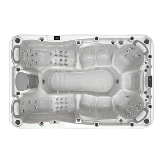
MAJOR COMPONENTS OF THE PRODUC T OLYMPUS... - Page 20 MAJOR COMPONENTS OF THE PRODUC T MONT BLANC (ELBRUS 230)
- Page 21 MAJOR COMPONENTS OF THE PRODUC T MONTE BIANCO (DISCOVERY)
- Page 22 MAJOR COMPONENTS OF THE PRODUC T MONTE ROSA (KILIMANJARO)
- Page 23 MAJOR COMPONENTS OF THE PRODUC T PARIS (ELBRUS 2018)
- Page 24 MAJOR COMPONENTS OF THE PRODUC T LONDON (MALAGA 2018)
- Page 25 MAJOR COMPONENTS OF THE PRODUC T MILAN (PALERMO 2018)
- Page 26 MAJOR COMPONENTS OF THE PRODUC T BERLIN (MARBELLA 2018)
- Page 27 MAJOR COMPONENTS OF THE PRODUC T TAURUS (KILIMANJARO)
- Page 28 MAJOR COMPONENTS OF THE PRODUC T LIBRA (ELBRUS 230)
- Page 29 MAJOR COMPONENTS OF THE PRODUC T HERCULES...
- Page 30 MAJOR COMPONENTS OF THE PRODUC T LEO P&P...
- Page 31 MAJOR COMPONENTS OF THE PRODUC T LEO SCANDI PACK...
- Page 32 MAJOR COMPONENTS OF THE PRODUC T ORION P&P...
- Page 33 MAJOR COMPONENTS OF THE PRODUC T ORION SCANDI PACK...
- Page 34 MAJOR COMPONENTS OF THE PRODUC T RIO GRANDE W-FLOW...
- Page 35 MAJOR COMPONENTS OF THE PRODUC T AMAZON W-FLOW...
- Page 36 MAJOR COMPONENTS OF THE PRODUC T DANUBE W-FLOW...
-
Page 37: User Interface
USER INTERFACE - EASY 4 EASY 4 COMPACT FULL-FUNCTION KEYPAD The Quick Reference Card provides an overview of your hot tub’s main functions and the operations accessible from your digital keypad. This QRC depicts a generic overlay, custom versions may vary. Heater Filter Smart Winter... - Page 38 USER INTERFACE - EASY 4 PROGRAMMING STEPS PROGRAM SETTING THE PROGRAMMING SETTING FILTER A filter cycle consists of start- OR PURGE CYCLE MENU CLOCK THE FILTER/ PURGE ing all the pumps and blower CYCLES START TIME in high speed for 1 minute The program menu is accessible Enter the program menu by (purge step) then, the pump...
- Page 39 USER INTERFACE - EASY 4 SETTING TEMPERA- SMART WINTER WATER TEMPERA- COOLDOWN TURE UNIT MODE TURE REGULATION After heating the hot tub wa- Water temperature can be Our Smart Winter Mode pro- Every 15 to 90 minutes the automatically turns the heater ter to the desired Set Point, displayed in either Fahrenheit tects your system from the cold...
-
Page 40: Easy
USER INTERFACE - EASY 7 EASY 7 KEYPAD LAYOUT Key 1 Settings Settings Light Key Mode Mode Selection Key 2 lights *Functions for keys 1 and 2 will depend on your system's low level configuration. SETTINGS KEY MODE KEY One press gives you access to a menu to Successive presses on the Mode key will give access to control different optional manage the settings of your hot tub. - Page 41 USER INTERFACE - EASY 7 START OR STOP ACCESSORIES WATER TEMPERATURE To start or stop an accessory, press the The temperature shown at the top of the the current temperature, Heating to xx.x associated button. Icons will become screen is the current water temperature. will be indicated.
- Page 42 USER INTERFACE - EASY 7 WATER CARE In Economy mode, the set point will be The Water Care section will help you set up your ideal filtration and heating reduced by 20°F*, which means that the heating system will not be engaged settings.
- Page 43 USER INTERFACE - EASY 7 HEAT PUMP This menu allow you to change the regulation mode of your heat pump. You can choose from Eco Heat, Smart Heat, Eco Auto, Smart Auto, Cool and Electric. A green checkmark indicates the currently selected regulation mode.
- Page 44 USER INTERFACE - EASY 7 AUDIO The Easy 7 can be used with the in.tune, The in.stream 2 Settings menu gives you The Audio option will only appear in the in.stream or in.stream 2 audio systems. a Source selector, a Bluetooth disconnect menu for keypads that are set up for an The Audio section in the Settings menu option, an On/Off switch and an audio...
- Page 45 USER INTERFACE - EASY 7 MAINTENANCE REMINDERS STANDBY through the list. The Easy 7 keypad will remind you of The Standby mode allows you to service maintenance required on your hot tub, To reset a task select it by pressing Light your hot tub.
- Page 46 USER INTERFACE - EASY 7 WIFI (IN.TOUCH ONLY) For the WiFi menu to appear in the To connect your in.touch module to a If the WiFi network is password protected Settings menu your in.touch module wireless network, use the Up/Down keys enter it when prompted.
- Page 47 USER INTERFACE - EASY 7 CONFIG Please do not make changes in the Once you have changed the Number of electrical configuration section unless Phases in the menu, you will be unable you are a qualified electrician. to use the Up/Down keys to return to the Low-level Configuration menu.
- Page 48 USER INTERFACE - EASY 7 IN.STREAM OPERATION Next track Volume up Mode Play/ Pause Last track Volume down Press the Mode key to access your in.stream. If you are using a device with Bluetooth technology, it must be connected for functions to work. Play/Pause audio Changing tracks Press the Play/Pause button to start or pause the audio.
- Page 49 USER INTERFACE - EASY 7 IN.STREAM 2 OPERATION Next track Volume up Mode Play/ Pause Last track Volume down Press the Mode key to access your in.stream 2. If you are using a device with Bluetooth technology, it must be connected for functions to work. Play/Pause audio Changing tracks Press the Play/Pause button to start or pause the audio.
- Page 50 USER INTERFACE - EASY 7 IN.CLEAR FUNCTIONS This menu is only available if an in.clear linked is detected. Power Boost adjustment Diagnostic Mode Boost activation/deactivation Press on the Mode key to access your in.clear module. Diagnostic Mode This menu allows you to activate or deactivate your in.clear, Press on the Diagnostic key to start a BromiCharge con- to start or stop a Boost, and to enter diagnostic mode.
- Page 51 USER INTERFACE - EASY 7 ERROR MESSAGES The list below shows the different error messages that can appear on the home screen. Refer to the troubleshooting and error codes section of the TechBook for your hot tub pack system. Code Message Warning! HL Error FLO - L01 FLO - L02 FLO...
- Page 52 USER INTERFACE - EASY 7 FEATURE MATRIX The following table presents the features and/or options available for the Easy 7 keypad, and the earliest software version at which this feature/option is available. All versions greater than the earliest version continue to support the feature. Keypad functions Earliest support Power...
-
Page 53: Smart Touch
USER INTERFACE - SMART TOUCH SMART TOUCH TOUCH SCREEN KEYPAD No buttons, keys and overlays! Mode and function selection wheels, all-on or all-off one touch activation key of last used settings, interactive display icons and on-screen messages are all elements of the Smart Touch user interface designed to let hot tub users interact intuitively with their hot tub and its value-added accessories. - Page 54 USER INTERFACE - SMART TOUCH SPA MODE SPA MODE START OR STOP ACCESSORIES WATER TEMPERATURE To select the spa mode, slide the left To start or stop an accessory (pump, The temperature shown at the bottom wheel up or down until the spa icon is blower, light), touch the associated of the screen shows the current water highlighted in the middle.
- Page 55 USER INTERFACE - SMART TOUCH SWIM SETTINGS To access your swim hot tub training The first one is Warm up. There, you The second one is Cooldown. There, drills, touch the swimmer icon on the can adjust the duration and intensity of you can adjust the duration and left.
- Page 56 USER INTERFACE - SMART TOUCH TRAINING DRILLS - ENDURANCE To select a training drill, touch the You can adjust the duration and inten- The preparation countdown is dis- training drill icon on the top of the right sity of your Endurance training drill by played, allowing you to get in position wheel icon.
- Page 57 USER INTERFACE - SMART TOUCH TRAINING DRILLS - LAP To select a training drill, touch the You can adjust the duration and The preparation countdown is dis- training drill icon on the top of the right intensity of your Lap training drill by played, allowing you to get in position wheel icon.
- Page 58 USER INTERFACE - SMART TOUCH TRAINING DRILLS - TRANSITION To select a training drill, touch the You can adjust the duration and inten- The preparation countdown is dis- training drill icon on the top of the right sity of your Transition training drill by played, allowing you to get in position wheel icon.
- Page 59 USER INTERFACE - SMART TOUCH TRAINING DRILLS - CARDIO To select a training drill, touch the You can adjust the duration and The preparation countdown is dis- training drill icon on the top of the right intensity of your Cardio training drill by played, allowing you to get in position wheel icon.
- Page 60 USER INTERFACE - SMART TOUCH TRAINING DRILLS - POWER To select a training drill, touch the You can adjust the duration and The preparation countdown is dis- training drill icon on the top of the right intensity of your Power training drill by played, allowing you to get in position wheel icon.
- Page 61 USER INTERFACE - SMART TOUCH TRAINING DRILLS - PERSONALIZED Three personalized training drills are Draw with your finger the desired Type your workout name. Once done, available and can be edited to create workout pattern on the screen. touch the return key to get back to the custom workouts.
- Page 62 USER INTERFACE - SMART TOUCH During the workout session, you can Touch Pause to suspend your swim If you touch Stop to interrupt your swim follow your progression with the swim- session. session, you will be able to change the mer icon moving toward right over the duration and/or the intensity of your Touch Resume when ready to swim...
- Page 63 USER INTERFACE - SMART TOUCH SETTINGS You can use the Settings mode to manage settings of your hot tub system. Direct to function selection wheel: Mode selection wheel: – water care settings icon – maintenance – date & time – keypad List of –...
- Page 64 USER INTERFACE - SMART TOUCH MODIFYING WATER CARE SCHEDULES In Economy mode, the set point will be You can modify the programmed Once you have set the schedule, use reduced by 20°F, which means that the schedules by selecting one and adjust- the calendar icon to go back.
- Page 65 USER INTERFACE - SMART TOUCH MAINTENANCE & ERROR LOG MAINTENANCE ERROR LOG REMINDERS To modify maintenance settings, slide Errors are archived by the system. Drag Smart Touch keypad will provide the right wheel until the maintenance the list Up and Down to move through reminders about maintenance required icon is highlighted in the middle.
- Page 66 USER INTERFACE - SMART TOUCH KEYPAD SETTING KEYPAD SETTINGS TEMPERATURE UNITS DISPLAY ORIENTATION To modify keypad settings, slide the Use this page to set or change the Use this page to set or change the nor- right wheel until the keypad icon is temperature in F˚...
- Page 67 USER INTERFACE - SMART TOUCH KEYPAD COLOR (OPTIONAL) If this option is available (depending on the hot tub configuration), the keypad rim color can be changed. 8 pre-de- fined colors are available. If the in.mix is installed, the keypad rim color can also be associated to an in.mix zone.
- Page 68 USER INTERFACE - SMART TOUCH WIFI WI-FI (IN.TOUCH 2) When a in.touch 2 is detected, this IN.TOUCH MODULE NOT CON- network will appear. NECTED If the in.touch module of your hot tub system is not connected, this message will be displayed. MISCELLANEOUS WARM WEATHER INFO MESSAGES...
- Page 69 USER INTERFACE - SMART TOUCH ABOUT This section shows information about the in.k1000 software number and the revision numbers of the different components of your system. ELECTRICAL CONFIGURATION Please do not make changes in this To change the low-level configuration, section unless you are a qualified the number of phases and the input electrician.
- Page 70 USER INTERFACE - SMART TOUCH AUDIO MODE (only available if the system detects a connected Aquasoul Pro audio station) Direct to function selection wheel: – on/off – speakers Mode – source selection wheel: – bluetooth audio mode Mute / last track / play/pause / next track To select the audio mode, slide the left wheel up or down until the audio icon menu is highlighted in the middle.
- Page 71 USER INTERFACE - SMART TOUCH SPEAKER CALIBRATION AUDIO SOURCE SELECTOR BLUETOOTH PAIRING TO CALIBRATE YOUR SPEAKERS TO SELECT AN AUDIO SOURCE If you are using a device with Bluetooth technology, it must be connected for Slide the right wheel until the speaker Slide the right wheel until the source functions to work.
- Page 72 USER INTERFACE - SMART TOUCH SANITIZATION MODE (only available if the system detects a connected in.clear water sanitization system) direct to function selection wheel: – on/off – bromicharge mode selection – boost levle wheel: – maintenance in.clear icon statuts and messages To select the sanitization mode, slide the left wheel up or down until the in.clear icon menu is highlighted in the middle.
- Page 73 USER INTERFACE - SMART TOUCH BROMICHARGE™ LEVEL When performing a test, To perform a water test, slide the right The green zone in the center area of the the BromiCharge™ gauge indicates gauge should be targeted for optimal wheel until the add BromiCharge™ icon the approximate sodium bromide level of performance.
- Page 74 USER INTERFACE - SMART TOUCH MAINTENANCE LEVEL Use a test kit to check the bromine level. MODIFY THE MAINTENANCE If you do, retest the bromine level the It should be between 3-5 ppm. If the LEVEL day after. If the bromine is not in the 3-5 bromine level stays within that range for range and is higher than 5 ppm, decrease To verify or modify the maintenance...
- Page 75 USER INTERFACE - SMART TOUCH COLOR MODE (only available if the in.mix is detected among the hot tub accessories) color wheel rainbow icon synchronization/ zone 1 desynchronization icon zone 2 mode selection zone 3 wheel: in.mix icon intensity By default, the in.mix selects Zone 2 when you access the menu. To select the color mode, slide the left wheel up or down until the in.mix icon menu is highlighted in the middle.
- Page 76 USER INTERFACE - SMART TOUCH TOO MUCH WATER ON DISPLAY WIPE SCREEN This message appears when too much water is detected on the touch screen. Simply wipe away excess water. INSTALLATION ERROR MESSAGES Upon connecting Smart Touch to your hot tub system you may see one of two error messages.
-
Page 77: And 1 Single Button Panel
USER INTERFACE - 4 AND 1 SINGLE BUT TON PANEL 4 BUTTON PANEL AUXILIARY KEYPAD FOR YOUR HOT TUB The 4 button panel is an auxiliary keypad designed to be installed as a second keypad on your hot tub. It allows you to run the accessories while staying comfortably seated in your hot tub. Its surface mount allows for an easy installation in different locations around your hot tub. -
Page 78: Optional Accessories
OPTIONAL ACCESSORIES - AQUASOUL PRO AQUASOUL PRO AUDIO STATION FOR HOT TUBS Aquasoul Pro audio system offers you the perfect means Aquasoul Pro is equipped with state of the art class D audio to bring music into your hot tub. Aquasoul Pro is simple to amplifiers. - Page 79 OPTIONAL ACCESSORIES - AQUASOUL PRO Depending on the chosen configuration, Aquasoul Pro can With a compatible keypad, you will have full control over the support up to 4 speakers, 1 subwoofer, an auxiliary input, a Aquasoul Pro features from inside of your hot tub. USB connection with 1A charging capability, FM radio receiv- er and Bluetooth streaming.
- Page 80 OPTIONAL ACCESSORIES - AQUASOUL PRO CONNECTIONS CONNECTING THE SPEAKERS AND SUBWOOFER Connector pins Identification Front Left speaker (+) Front Left speaker (-) Front Right speaker (-) Front Right speaker (+) Rear Left speaker (+) Rear Left speaker (-) Rear Right speaker (-) Rear Right speaker (+) Subwoofer (+) Subwoofer (-)
- Page 81 OPTIONAL ACCESSORIES - AQUASOUL PRO CONNECTIONS NOTE: In basic configuration (not connected to a keypad or PAIRING WITH A BLUETOOTH ENABLED DEVICE controller), Aquasoul Pro is set in Bluetooth mode. Otherwise, Aquasoul Pro can play music from any device equipped with please refer to your specific keypad operating manual for details Bluetooth wireless technologies, however, you must pair on the Aquasoul Pro functions.
-
Page 82: My Music
OPTIONAL ACCESSORIES - MY MUSIC MY MUSIC NO EXTERNAL CONTROL UNIT 1. Listening to music via Bluetooth 1.2 Listening to music via Bluetooth device 1.1 Pairing Bluetooth devices 1. The Bluetooth mode is activated as soon as it is paired with a Bluetooth device. -
Page 83: In.clear
OPTIONAL ACCESSORIES - IN.CLEAR IN.CLEAR Bromine based water sanitization system for hot tub On/Off Maintenance START UP PROCEDURE (Instruction video: www.geckoal.com/inclear) 1. Fill the hot tub with water. Your goal is a residual bromine bank of 3 – 5 ppm. If the bromine content of your water is less than 3 ppm, press 2. - Page 84 OPTIONAL ACCESSORIES - IN.CLEAR INTRODUCTION EFFECTS OF BROMINE HOW THE IN.CLEAR WORKS • Bromine destroys waterborne bacteria. When sodium bromide (such as BromiCharge) is added to • Bromine destroys algae in water (e.g. Black, Green, Mus- the water, it separates into sodium ions and bromide ions. tard).
- Page 85 OPTIONAL ACCESSORIES - IN.CLEAR BEFORE STARTING (see video: www.geckoal.com/inclear) 1. DRAIN AND CLEAN THE HOT TUB 4. ADD SODIUM BROMIDE (SUCH AS BROMICH- ARGE) It’s important to completely drain and clean the hot tub to remove all residues accumulated on the surface and inside or Water temperature between 32°...
- Page 86 OPTIONAL ACCESSORIES - IN.CLEAR IN.CLEAR OPERATING MODES This manual details the functions of the in.clear with the default keypad (in.k200). If your hot tub pack uses a compatible key- pad (ex. in.k800) please see its manual for more specific information. It is important to note that the in.clear system can ONLY MAINTENANCE MODE generate bromine when the water is circulating.
- Page 87 OPTIONAL ACCESSORIES - IN.CLEAR KEYPAD FUNCTIONS keypad display. Do not turn the BOOST KEY PROGRAM KEY +/- KEYS DIAGNOSTIC MODE in.clear off unless required for Diagnostic mode can be used maintenance, or if advised by a to periodically adjust the Press and hold Use the Up and Down keys The first press of the Boost key...
- Page 88 OPTIONAL ACCESSORIES - IN.CLEAR START UP PROCEDURE Set the maintenance level DETERMINE THE BOOST LEVEL Determining the proper maintenance level for your hot tub Every time you use your hot tub, activate the boost mode. As is an extremely important step. DO NOT use your hot tub a rule of thumb, the boost level corresponds to the number during this step as it will slow the process.
- Page 89 OPTIONAL ACCESSORIES - IN.CLEAR TROUBLESHOOTING LOW SODIUM LOW SODIUM BRO- BROMIDE ERROR MIDE WARNING Low Sodium Bromide Error Low Sodium Bromide If after adding sodium (Err) occurs when the sodium Warning (Lo) indicates the need bromide the Low Sodi- bromide level is too low. The lo to add sodium bromide to the um Bromide Warning LED indicator will blink when...
- Page 90 OPTIONAL ACCESSORIES - IN.CLEAR HIGH SODIUM BRO- IN.CLEAR IS FLO ERROR (OUT COMMUNICATION MIDE WARNING TURNED OFF OF DIAGNOSTIC ERROR MODE) High Sodium Bromide Warning The OFF message indicates that The Co error indicates that a (Hi) occurs when too much the in.clear is turned off.
-
Page 91: In.clear (In Smart Touch)
OPTIONAL ACCESSORIES - IN.CLEAR (IN SMART TOUCH) IN.CLEAR OPERATING MODES IF YOU ARE A USING A SMART TOUCH, PLEASE REFER TO THE USER INTERFACE SECTION TO GET THE IN- STRUCTIONS ABOUT THE SANITIZATION MODE. direct to function selection wheel: – on/off –... - Page 92 OPTIONAL ACCESSORIES - IN.CLEAR (IN SMART TOUCH) START UP PROCEDURE IF YOU ARE A USING A SMART TOUCH, PLEASE REFER TO THE USER INTERFACE SECTION TO GET THE IN- STRUCTIONS ABOUT THE SANITIZATION MODE. SET THE MAINTENANCE LEVEL DETERMINE THE BOOST LEVEL Determining the proper maintenance level for your hot tub Every time you use your hot tub, activate the boost mode.
- Page 93 OPTIONAL ACCESSORIES - IN.CLEAR (IN SMART TOUCH) TROUBLESHOOTING ERROR MESSAGES WILL APPEAR ONLY WHEN IN SANITIZATION MODE. BROMICHARGE LEVEL TOO LOW LOW SODIUM BROMIDE WARN- INPUT AC Low Sodium Bromide Error occurs A input AC message displayed on the when the sodium bromide level is too Low Sodium Bromide Warning indi- keypad indicates that there is a prob- low.
- Page 94 OPTIONAL ACCESSORIES - IN.CLEAR (IN SMART TOUCH) TROUBLESHOOTING NO FLOW CONDITION COMMUNICATION ERROR (OUT OF DIAGNOSTIC MODE) The lost communication error indicates that a linked version of the in.clear With the linked version, this message is being used, but a pack cannot be appears when the in.clear's pressostat detected.
- Page 95 OPTIONAL ACCESSORIES - IN.CLEAR FREQUENTLY ASKED QUESTIONS Q: WHY IS MY HOT TUB WATER CLOUDY/OILY? Q: WHEN MY IN.CLEAR BROMINE GENERATOR IS OFF DOES THE SODIUM BROMIDE CONTINUE SANI- A: If your hot tub becomes cloudy or oily due to bather load perform an additional Boost and wait for 24 hours to see if TIZING MY HOT TUB? conditions return to normal.
- Page 96 OPTIONAL ACCESSORIES - IN.CLEAR CELL CLEANING In.clear includes a self-cleaning feature to prevent scale Phosphoric acid deposits on the graphite electrodes of the in.clear system. or muriatic acid However, deposits may still form due to hard water. If that happens the cell should be cleaned in an acidic solution. All power must be disconnected before any service proce- dure is performed.
-
Page 97: Uv-C / Ozone
OPTIONAL ACCESSORIES - UV-C / OZONE UV-C WATER TREATMENT 1- Water resistant lid 2- Aluminum nut 3- Lamp casing, wire outlet 4- Germicidal ultraviolet lamp 5- Rubber sealing ring 6- Quartz sleeve 7- Chamber 8- Pawl 9- Transformer WARNING: THE GERMICIDAL ULTRAVIOLET RAYS CHANGING THE LAMP AND SERVICING THE UV ARE HARMFUL TO THE EYES, SKIN. -
Page 98: In.grid
OPTIONAL ACCESSORIES - IN.GRID in.grid INSTALLATION The in.grid provides a connection to a normally open dry- A FLEXIBLE WAY TO CONTROL EXTERNAL HEAT contact relay on a spring-loaded female connector. The SOURCES FOR YOUR HOT TUB connector accepts bare wire connections. The cable must be Our new system interface lets you select, use and synchro- passed through the already installed watertight grommet. - Page 99 OPTIONAL ACCESSORIES - IN.GRID INSTALLATION WITH EXTERNAL HEAT PUMP OR GAS HEATER in.grid Hot tub circulation/ Hot tub control main pump system Pump heater or gas heater IMPORTANT: Your heat pump or gas heater must have You need to be sure your pump heater or gas heater is all the flow and temperature limit protections.
- Page 100 OPTIONAL ACCESSORIES - IN.GRID Heat Mode Operations You can choose between four different water regulation Freeze Protection modes available. Your in.grid is automatically detected by the Freeze protection has been added because EXT (EXTERNAL) hot tub control system at power up. It will be ready to use with mode does not allow the activation of the internal heater.
- Page 101 OPTIONAL ACCESSORIES - IN.TOUCH 2 HOME TRANSMITTER (EN MODULE) INSTALLATION The Home Transmitter unit must be installed inside the Here are some suggestions for a successful installation: house near the router as it needs to be connected to • If possible, install device on the first floor of your it.
- Page 102 OPTIONAL ACCESSORIES - IN.TOUCH 2 PAIRING THE HOT TUB TRANSMITTER (CO MODULE) AND THE HOME TRANSMITTER (EN MODULE) The pairing process is used when you need to replace one module of the in.touch 2 kit. Otherwise, the in.touch 2 arrives pre-paired from the factory. 1.
- Page 103 OPTIONAL ACCESSORIES - IN.TOUCH 2 Each in.touch 2 module has a status LED that can be used for troubleshooting purposes. The LED is located on the top of both enclosures. status status Home Transmitter Hot tub Transmitter Pairing mode Pairing mode Yellow (Blinking) Yellow (Blinking) Router not detected Red...
- Page 104 OPTIONAL ACCESSORIES - IN.TOUCH 2 DOWNLOAD APPLICATION The in.touch app allows you to control your hot tub using your home network or an Internet connection anywhere in the world. The in.touch 2 app is waiting for you in the App Store for iOS devices and on Google Play for Android —...
- Page 105 OPTIONAL ACCESSORIES - IN.TOUCH 2 SETUP YOUR WI-FI ON YOUR DEVICE Before using your application, go to the Wi-Fi section of your device’s settings. Make sure you are connected to your home network. This needs to be the same Wi-Fi provided by the router to which you connected your Home Transmitter.
- Page 106 OPTIONAL ACCESSORIES - IN.TOUCH 2 START THE IN.TOUCH 2 APPLICATION Find the icon for the in.touch 2 application, then tap on it to open it. The first time you use the application a message will ask you: “in.touch 2” Would like to send you notifications. If you choose Allow, the application will send you notifications about the status of your hot tub.
- Page 107 OPTIONAL ACCESSORIES - IN.TOUCH 2 LOGIN PAGE Before using your application, you must create an account first and then, you’ll be able to sign in. Your account will give you the opportunity to have access to your hot tub from any in.touch 2 application. NEW ACCOUNT CREATION When you choose to create a new account, you agree at the same time our Terms of Service and our Privacy Policy.
- Page 108 OPTIONAL ACCESSORIES - IN.TOUCH 2 CHOOSE A SPA This page displays all the hot tubs detected by your application. To detect your hot tub, you need to connect your mobile device to the same network to which you connected your Home Transmitter. Once you have done a connection with the hot tub its name will be saved on this page to allow you to connect to this hot tub from anywhere.
- Page 109 OPTIONAL ACCESSORIES - IN.TOUCH 2 SPA STATE This page displays all the active states of your hot tub. Below is a quick description of each state you may encounter on your hot tub. Each state is associated to a priority and color that determines the color of the widget on the home page.
- Page 110 OPTIONAL ACCESSORIES - IN.TOUCH 2 TURN ON/OFF ACCESSORIES According to your hot tub pack configuration, you can start or stop an accessory by simply touching the associated icon. The icon will become animated when the accessory is on. Simply press on the icon to start or stop the accessory.
- Page 111 OPTIONAL ACCESSORIES - IN.TOUCH 2 CONTROL YOUR IN.MIX 300 This menu is only available if an in.mix 300 is detected in your hot tub accessories To turn on or off the in.mix 300, you can use, if you want, the light icon on your home page. To go to your in.mix 300 page, simply swap to the left.
- Page 112 OPTIONAL ACCESSORIES - IN.TOUCH 2 WATER CARE The Water Care page will help you set up your ideal filtration and heating set- tings. Choose between Away from Home, Beginner, Energy Savings, Super Energy and Weekender, depending on your need. Touch the Water Care name you would like to activate, a green checkmark will appear on the icon, indicating you have selected it.
- Page 113 OPTIONAL ACCESSORIES - IN.TOUCH 2 REMINDERS Reminders page will help you to make a follow-up of your maintenance. The in.touch 2 will remember you to perform required maintenance tasks on your hot tub, such as rinse filter or clean filter. Each task has its own reminder duration based on normal use.
- Page 114 OPTIONAL ACCESSORIES - IN.TOUCH 2 MODIFYING SCHEDULES In this menu it is possible to add, remove or edit schedules of economy or filtration. To have access to this menu, simply touch the tabs: Water Care menu - the little pen at the right of the wanted water care Touch the Economy tab to modify the economy schedules and Filter cycle tab for the filtration schedules.
-
Page 115: In.touch
OPTIONAL ACCESSORIES - IN.TOUCH 2 SPA SETTINGS In the Settings page you can access the following: in.touch network Temperature units Change spa name Technical info To select an item, tap on the arrow next to it. It will open the selected menu. - Page 116 OPTIONAL ACCESSORIES - IN.TOUCH 2 CHANGE CHANNEL The Change channel page allows you to change the chan- nel used by the two in.touch 2 modules. In some cases, this can help you to have a stronger signal. You can have access to this page by touching the fol- lowing tabs: Spa settings (at the bottom right) - in.touch network - channel TEMPERATURE UNITS...
- Page 117 OPTIONAL ACCESSORIES - IN.TOUCH 2 NAME This section allows you to edit the name of the hot tub. You can have access to this page by touching the follow- ing tabs: Spa settings (at the bottom right) - Change hot tub name TECHNICAL INFO This section shows information about the in.touch 2 soft-...
- Page 118 OPTIONAL ACCESSORIES - IN.TOUCH 2 SETTINGS In the Settings page you can access the following: Add a hot tub from local network Account Tutorial *Legal **Patents To select an item, tap on the arrow next to it. It will open the selected menu. *The button Legal will bring you to this web site : https://geckointouch.com/legal **The button Patents will bring you to this web site:...
- Page 119 OPTIONAL ACCESSORIES - IN.TOUCH 2 ACCOUNT This section gives you access to your account information. You can have access to this page by touching the following tabs: Settings (up right corner) - account TUTORIAL This section gives you a quick over- view of your in.touch 2 application’s functions.
- Page 120 OPTIONAL ACCESSORIES - IN.TOUCH 2 TECHNICAL SUPPORT INVITATION When you receive an invitation for Technical Support, a red circle will be displayed next to the “setting” logo (top right corner). AUTHORIZING AN INVITATION All the invitations you may receive are under the dealers tab in the “settings”...
- Page 121 OPTIONAL ACCESSORIES - IN.TOUCH 2 DEALER PAGE Once you’ve had a dealer on your in.touch 2 app, you can, at all times, have access to his information. If you don’t want your dealer to have access to your hot tub anymore, simply swap to the left the “Allow access to your spa”...
- Page 122 OPTIONAL ACCESSORIES - IN.TOUCH 2 HOME TRANSMITTER (EN MODULE) LED STATUS This module’s LED can show various status conditions, as indicated below. Rapidly flashing YELLOW color: GREEN color: The Home Transmitter is in pairing mode when this color Reason? is shown (the pairing switch was pressed). Until a pairing The Home Transmitter is connected to a router (an IP successfully completes, the application cannot connect address was assigned), but the in.touch 2 server is not...
- Page 123 OPTIONAL ACCESSORIES - IN.TOUCH 2 HOT TUB TRANSMITTER (CO MODULE) LED STATUS This module’s LED can show various status conditions, as shown below. Rapidly flashing YELLOW color: Blinking LED: The Hot tub Transmitter is in pairing mode when this On both modules, if the LED is blinking about once color is shown.
-
Page 124: Sand Filter System
OPTIONAL ACCESSORIES - SAND FILTER SYSTEM SAND FILTER SYSTEM FILTRATION While the pump is switched off set the valve to “FILTRATION”. ACCESSORIES OF THE SAND FILTRATION SYSTEM: Switch the pump on. – filter tank While the pump is on occasionally check the pressure gauge –... -
Page 125: Water Treatment Basics
WATER TREATMENT BASICS 6. Water analysers: WATER TREATMENT BASICS The chemical equilibrium of the water There are several types of water analysers which are mostly used to measure chemical and disinfectant effect. The hot tub water will be clean and clear if its chemical com- Chemical (pH);... -
Page 126: Maintenance
MAINTENANCE Operating the hot tub without a filter cartridge is PROHIBITED FILTER CARTRIDGE REMOVAL AND CLEANING Cleaning mechanical contaminations via continuous water 1. Remove the lid of the filter. circulation and chemical mixture is a basic requirement for 2. Take out the filter cartridge. proper cleaning of the hot tub water. -
Page 127: Wiring Diagram W2000
WIRING DIAGRAM - W2000 W2000 OVERVIEW Probe connectors heat.wav power con- (heat.wav's low voltage nection cable or regulation probe and overheat captor model-re) Light output (12 V DC) Bonding lugs Communication link (in.touch or in.stik) Main power entry Main keypad connection connector Power output drivers... - Page 128 WIRING DIAGRAM - W2000 CONNECTIONS CONNECTING HIGH VOLTAGE ACCESSORIES: NORTH AMERICAN MODEL IN.YJ Wires to connect high voltage accessories must have 0.25” quick-connect terminals. These tabs require high-voltage accessories to have straight, non-insulated, female quick-connect terminals for all connec- tions, including ground. Depending on where the connections are made on the in.yj pack PCB, 120 V and 240 V accessories are supported.
- Page 129 WIRING DIAGRAM - W2000 CONNECTIONS CONNECTING HIGH VOLTAGE ACCESSORIES: NORTH AMERICAN HEAT RECOVERY MODEL IN.YJ-RE These tabs require high-voltage accessories to have straight, non-insulated, female quick-connect terminals for all connec- tions, including ground. Refer to the following tables for correct connections. Note that all female terminals must be correctly and completely seated on the PCB tab for proper current ratings.
- Page 130 WIRING DIAGRAM - W2000 CONNECTIONS COMPLETING THE INSTALLATION Strain relief bracket Foam gasket Molded strain relief channels For 12-3 /14-4/14-3 cable size For 14-3 /18-3 cable size Output cable opening size...
- Page 131 WIRING DIAGRAM - W2000 ELECTRICAL WIRING ELECTRICAL WIRING: ALL MODELS Bonding lugs Main power entry Main power entry To complete the electrical connections of the in.yj control WARNING! system you will need a Phillips screwdriver and a flat-head Disconnect power before starting electrical work. screwdriver.
-
Page 132: W3000 & W5000
WIRING DIAGRAM - W2000 ELECTRICAL WIRING ELECTRICAL WIRING: NORTH AMERICAN MODEL Refer to wiring diagram in the enclosure box lid for more information. 120 V (3 WIRES) 240 V (4 WIRES) DO NOT REMOVE THE BROWN WIRE. Insert each wire into Remove the brown wire and insert each wire into the appro- the appropriate socket of the main entry terminal block priate socket of the main entry terminal block according to... - Page 133 WIRING DIAGRAM - W3000 & W5000 W3000 & W5000...
- Page 134 WIRING DIAGRAM - W3000 & W5000 CONNECTIONS CONNECTING HIGH VOLTAGE ACCESSORIES: ALL MODELS Two options are available with Y Series hot tub packs for connecting high voltage accessories: 0.250” quick-connect terminals, or AMP connectors conform to industry standards. CONNECTING HIGH VOLTAGE ACCESSORIES: NORTH AMERICAN MODEL IN.YE For the connection to the 0.250 inch terminals, the high voltage accessories must be provided with female quick connect termi- nals, straight and non-insulated for all types of connections, including the ground.
- Page 135 WIRING DIAGRAM - W3000 & W5000 CONNECTIONS HEAT.WAV WATER HEATER CONNECTIONS Live Return Ground in.flo flo Regulation probe All Y Series systems come with a high performance heat.wav The heat.wav heater is factory configured for 240 V / 4 kW, heater.
-
Page 136: W8000
WIRING DIAGRAM - W8000... - Page 137 WIRING DIAGRAM - W8000 CONNECTIONS CONNECTING HIGH VOLTAGE ACCESSORIES: NORTH AMERICAN MODEL IN.YT For the connection to the 0.250 inch terminals, the high voltage accessories must be provided with female quick connect termi- nals, straight and non-insulated for all types of connections, including the ground. Accessories of 120 V or 240 V may be connected to the corresponding terminals of the printed circuit of the in.yt.
- Page 138 WIRING DIAGRAM - W8000 CONNECTIONS HEAT.WAV WATER HEATER CONNECTIONS All Y Series systems come with a high performance heat.wav The heat.wav heater is factory configured for 240 V / 4 kW, heater. With no pressure switch, it features in.flo integrated but it can be converted to a dedicated 120 V / 1 kW by simply dry-fire protection.
-
Page 139: Breaker Setting
BREAKER SET TING POWER UP AND BREAKER SETTING It is important to specify Choose the number of The values displayed by the the current rating of the phases supplying your hot system correspond to 80% tub (1 to 3). Use the Up or GFCI/RCD used to ensure a of the maximum amperage Down keys to select the... - Page 140 BREAKER SET TING POWER UP AND BREAKER SETTING IMPORTANT Please read the following before starting the device. Verify that all accessories are linked to the ground lug and connected to the to the control system. A minimum flow of 68 LPM (18 GPM) is required. Make sure that all valves are open in the hot tub plumbing and that the water flow is sufficient between the main pump and the water heater.
-
Page 141: Frequently Asked Questions
FREQUENTLY ASKED QUESTIONS Is a floor drain necessary for an indoor hot tub? QUESTIONS CONCERNING CLEANING, WATER TREATMENT, AND MAINTENANCE Building a floor drain is mandatory! What should I do if the filter of the hot tub is polluted? TECHNICAL DATE OF THE PRODUCT, USAGE Clean the filter every week or two weeks with a jet of water. - Page 142 FREQUENTLY ASKED QUESTIONS When we do not use the hot tub often, mostly in the What is the service life of the UV-C lamp? winter (around 3 times a week), which is the most If the filtration cycle is set to the continuous (0-24) setting, energy efficient setting, taking into account the energy then the service life of the UV-C lamp is 8000-9000 hours.
- Page 144 The products included in the user manual are for illustration purposes only, and may not always match the specifications of the advertised product. Manufacturer reserves the right to modify the products – including the product range – without prior notice since they are valid at the time they are delivered to the printing press.
Need help?
Do you have a question about the Olympus and is the answer not in the manual?
Questions and answers
What is the dry weight of my OrionP&P?