ABB Symphony Harmony Series Instruction
Hydraulic servo termination unit
Hide thumbs
Also See for Symphony Harmony Series:
- Instruction (402 pages) ,
- Instructions manual (132 pages) ,
- Instructions manual (66 pages)
Table of Contents
Advertisement
Quick Links
Advertisement
Table of Contents

Related Manuals for ABB Symphony Harmony Series


Summary of Contents for ABB Symphony Harmony Series
- Page 1 Instruction Harmony Series Hydraulic Servo T ermination U nit NTHS03...
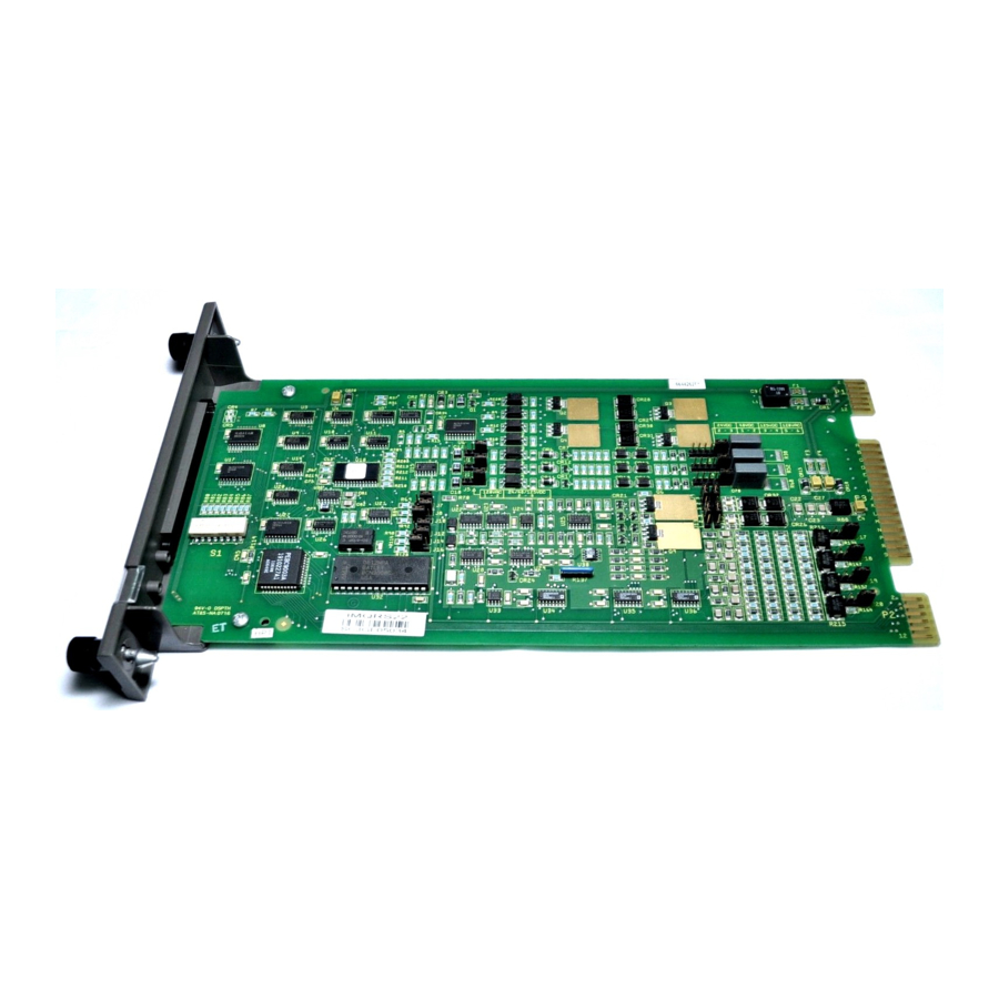
- Page 2 Preface The NTHS03 Hydraulic Servo Termination Unit is a Harmony rack I/O device that is part of the Symphony Enterprise Man- agement and Control System. It provides a signal path between an IMHSS03 Hydraulic Servo module and hydraulic servo valve, I/H converter, or linear variable differential transformer. This instruction explains the NTHS03 termination unit specifi- cations and operation.
- Page 3 List of Effective Pages Total number of pages in this instruction is 32, consisting of the following: Page No. Change Date Preface Original List of Effective Pages Original iii through viii Original 1-1 through 1-7 Original 2-1 through 2-8 Original 3-1 through 3-5 Original 4-1 through 4-3...
- Page 4 Table of Contents Section 1 Introduction ....................1-1 Overview ........................1-1 Intended User ......................1-1 Description ......................1-2 Mounting Hardware ....................1-2 Instruction Content....................1-3 How to Use this Instruction ..................1-3 Document Conventions .................... 1-4 Reference Documents....................1-4 Related Nomenclature ....................1-4 Specifications......................
-
Page 5: Table Of Contents
List of Figures Title Page 1-1. Harmony Rack I/O Architecture ..............1-2 1-2. Mounting Hardware...................1-3 2-1. Termination Unit Layout................2-3 2-2. Termination Unit Installation..............2-5 2-3. Cable Connections..................2-6 2-4. Terminal Assignments ................2-7 List of Tables Title Page 1-1. Reference Documents ................1-4 1-2. Related Nomenclature................1-4 1-3. - Page 6 Safety Summary Electrostatic Sensitive Device Devices labeled with this symbol require special handling precau- tions as described in the installation section. GENERAL Equipment Environment WARNINGS All components, whether in transportation, operation or storage, must be in a noncorrosive environment. Electrical Shock Hazard During Maintenance Disconnect power or take precautions to insure that contact with energized parts is avoided when servicing.
- Page 7 Safety Summary (continued) SPECIFIC Remove a module from its assigned slot before installing or remov- CAUTIONS ing a cable assigned to that slot. Failure to do so could result in damage to the module. (p. 2-6, 4-2) WBPEEUI260047A0...
- Page 8 ABB will provide assistance in the operation and repair of its products. Requests for sales or application services should be made to your nearest sales or service office. ABB can also pro- vide installation, repair and maintenance contract services. When ordering parts, use nomenclature or part numbers and part descriptions from equipment manuals.
- Page 9 Trademarks and Registrations Registrations and trademarks used in this document include: ® INFI 90 Registered trademark of Elsag Bailey Process Automation ™ Symphony Trademark of Elsag Bailey Process Automation viii WBPEEUI260047A0...
- Page 10 Preface The NTHS03 Hydraulic Servo Termination Unit is a Harmony rack I/O device that is part of the Symphony Enterprise Man- agement and Control System. It provides a signal path between an IMHSS03 Hydraulic Servo module and hydraulic servo valve, I/H converter, or linear variable differential transformer. This instruction explains the NTHS03 termination unit specifi- cations and operation.
- Page 11 List of Effective Pages Total number of pages in this instruction is 32, consisting of the following: Page No. Change Date Preface Original List of Effective Pages Original iii through viii Original 1-1 through 1-7 Original 2-1 through 2-8 Original 3-1 through 3-5 Original 4-1 through 4-3...
- Page 12 Table of Contents Section 1 Introduction ....................1-1 Overview ........................1-1 Intended User ......................1-1 Description ......................1-2 Mounting Hardware ....................1-2 Instruction Content....................1-3 How to Use this Instruction ..................1-3 Document Conventions .................... 1-4 Reference Documents....................1-4 Related Nomenclature ....................1-4 Specifications......................
-
Page 13: List Of Tables
List of Figures Title Page 1-1. Harmony Rack I/O Architecture ..............1-2 1-2. Mounting Hardware...................1-3 2-1. Termination Unit Layout................2-3 2-2. Termination Unit Installation..............2-5 2-3. Cable Connections..................2-6 2-4. Terminal Assignments ................2-7 List of Tables Title Page 1-1. Reference Documents ................1-4 1-2. Related Nomenclature................1-4 1-3. - Page 14 Safety Summary Electrostatic Sensitive Device Devices labeled with this symbol require special handling precau- tions as described in the installation section. GENERAL Equipment Environment WARNINGS All components, whether in transportation, operation or storage, must be in a noncorrosive environment. Electrical Shock Hazard During Maintenance Disconnect power or take precautions to insure that contact with energized parts is avoided when servicing.
- Page 15 Safety Summary (continued) SPECIFIC Remove a module from its assigned slot before installing or remov- CAUTIONS ing a cable assigned to that slot. Failure to do so could result in damage to the module. (p. 2-6, 4-2) WBPEEUI260047A0...
- Page 16 ABB will provide assistance in the operation and repair of its products. Requests for sales or application services should be made to your nearest sales or service office. ABB can also pro- vide installation, repair and maintenance contract services. When ordering parts, use nomenclature or part numbers and part descriptions from equipment manuals.
- Page 17 Trademarks and Registrations Registrations and trademarks used in this document include: ® INFI 90 Registered trademark of Elsag Bailey Process Automation ™ Symphony Trademark of Elsag Bailey Process Automation viii WBPEEUI260047A0...
- Page 18 Preface The NTHS03 Hydraulic Servo Termination Unit is a Harmony rack I/O device that is part of the Symphony Enterprise Man- agement and Control System. It provides a signal path between an IMHSS03 Hydraulic Servo module and hydraulic servo valve, I/H converter, or linear variable differential transformer. This instruction explains the NTHS03 termination unit specifi- cations and operation.
- Page 19 List of Effective Pages Total number of pages in this instruction is 32, consisting of the following: Page No. Change Date Preface Original List of Effective Pages Original iii through viii Original 1-1 through 1-7 Original 2-1 through 2-8 Original 3-1 through 3-5 Original 4-1 through 4-3...
- Page 20 Table of Contents Section 1 Introduction ....................1-1 Overview ........................1-1 Intended User ......................1-1 Description ......................1-2 Mounting Hardware ....................1-2 Instruction Content....................1-3 How to Use this Instruction ..................1-3 Document Conventions .................... 1-4 Reference Documents....................1-4 Related Nomenclature ....................1-4 Specifications......................
- Page 21 List of Figures Title Page 1-1. Harmony Rack I/O Architecture ..............1-2 1-2. Mounting Hardware...................1-3 2-1. Termination Unit Layout................2-3 2-2. Termination Unit Installation..............2-5 2-3. Cable Connections..................2-6 2-4. Terminal Assignments ................2-7 List of Tables Title Page 1-1. Reference Documents ................1-4 1-2. Related Nomenclature................1-4 1-3.
- Page 22 Safety Summary Electrostatic Sensitive Device Devices labeled with this symbol require special handling precau- tions as described in the installation section. GENERAL Equipment Environment WARNINGS All components, whether in transportation, operation or storage, must be in a noncorrosive environment. Electrical Shock Hazard During Maintenance Disconnect power or take precautions to insure that contact with energized parts is avoided when servicing.
- Page 23 Safety Summary (continued) SPECIFIC Remove a module from its assigned slot before installing or remov- CAUTIONS ing a cable assigned to that slot. Failure to do so could result in damage to the module. (p. 2-6, 4-2) WBPEEUI260047A0...
- Page 24 ABB will provide assistance in the operation and repair of its products. Requests for sales or application services should be made to your nearest sales or service office. ABB can also pro- vide installation, repair and maintenance contract services. When ordering parts, use nomenclature or part numbers and part descriptions from equipment manuals.
- Page 25 Trademarks and Registrations Registrations and trademarks used in this document include: ® INFI 90 Registered trademark of Elsag Bailey Process Automation ™ Symphony Trademark of Elsag Bailey Process Automation viii WBPEEUI260047A0...
- Page 26 Preface The NTHS03 Hydraulic Servo Termination Unit is a Harmony rack I/O device that is part of the Symphony Enterprise Man- agement and Control System. It provides a signal path between an IMHSS03 Hydraulic Servo module and hydraulic servo valve, I/H converter, or linear variable differential transformer. This instruction explains the NTHS03 termination unit specifi- cations and operation.
- Page 27 List of Effective Pages Total number of pages in this instruction is 32, consisting of the following: Page No. Change Date Preface Original List of Effective Pages Original iii through viii Original 1-1 through 1-7 Original 2-1 through 2-8 Original 3-1 through 3-5 Original 4-1 through 4-3...
- Page 28 Table of Contents Section 1 Introduction ....................1-1 Overview ........................1-1 Intended User ......................1-1 Description ......................1-2 Mounting Hardware ....................1-2 Instruction Content....................1-3 How to Use this Instruction ..................1-3 Document Conventions .................... 1-4 Reference Documents....................1-4 Related Nomenclature ....................1-4 Specifications......................
- Page 29 List of Figures Title Page 1-1. Harmony Rack I/O Architecture ..............1-2 1-2. Mounting Hardware...................1-3 2-1. Termination Unit Layout................2-3 2-2. Termination Unit Installation..............2-5 2-3. Cable Connections..................2-6 2-4. Terminal Assignments ................2-7 List of Tables Title Page 1-1. Reference Documents ................1-4 1-2. Related Nomenclature................1-4 1-3.
- Page 30 Safety Summary Electrostatic Sensitive Device Devices labeled with this symbol require special handling precau- tions as described in the installation section. GENERAL Equipment Environment WARNINGS All components, whether in transportation, operation or storage, must be in a noncorrosive environment. Electrical Shock Hazard During Maintenance Disconnect power or take precautions to insure that contact with energized parts is avoided when servicing.
- Page 31 Safety Summary (continued) SPECIFIC Remove a module from its assigned slot before installing or remov- CAUTIONS ing a cable assigned to that slot. Failure to do so could result in damage to the module. (p. 2-6, 4-2) WBPEEUI260047A0...
- Page 32 ABB will provide assistance in the operation and repair of its products. Requests for sales or application services should be made to your nearest sales or service office. ABB can also pro- vide installation, repair and maintenance contract services. When ordering parts, use nomenclature or part numbers and part descriptions from equipment manuals.
- Page 33 Trademarks and Registrations Registrations and trademarks used in this document include: ® INFI 90 Registered trademark of Elsag Bailey Process Automation ™ Symphony Trademark of Elsag Bailey Process Automation viii WBPEEUI260047A0...
- Page 34 Preface The NTHS03 Hydraulic Servo Termination Unit is a Harmony rack I/O device that is part of the Symphony Enterprise Man- agement and Control System. It provides a signal path between an IMHSS03 Hydraulic Servo module and hydraulic servo valve, I/H converter, or linear variable differential transformer. This instruction explains the NTHS03 termination unit specifi- cations and operation.
- Page 35 List of Effective Pages Total number of pages in this instruction is 32, consisting of the following: Page No. Change Date Preface Original List of Effective Pages Original iii through viii Original 1-1 through 1-7 Original 2-1 through 2-8 Original 3-1 through 3-5 Original 4-1 through 4-3...
- Page 36 Table of Contents Section 1 Introduction ....................1-1 Overview ........................1-1 Intended User ......................1-1 Description ......................1-2 Mounting Hardware ....................1-2 Instruction Content....................1-3 How to Use this Instruction ..................1-3 Document Conventions .................... 1-4 Reference Documents....................1-4 Related Nomenclature ....................1-4 Specifications......................
- Page 37 List of Figures Title Page 1-1. Harmony Rack I/O Architecture ..............1-2 1-2. Mounting Hardware...................1-3 2-1. Termination Unit Layout................2-3 2-2. Termination Unit Installation..............2-5 2-3. Cable Connections..................2-6 2-4. Terminal Assignments ................2-7 List of Tables Title Page 1-1. Reference Documents ................1-4 1-2. Related Nomenclature................1-4 1-3.
- Page 38 Safety Summary Electrostatic Sensitive Device Devices labeled with this symbol require special handling precau- tions as described in the installation section. GENERAL Equipment Environment WARNINGS All components, whether in transportation, operation or storage, must be in a noncorrosive environment. Electrical Shock Hazard During Maintenance Disconnect power or take precautions to insure that contact with energized parts is avoided when servicing.
- Page 39 Safety Summary (continued) SPECIFIC Remove a module from its assigned slot before installing or remov- CAUTIONS ing a cable assigned to that slot. Failure to do so could result in damage to the module. (p. 2-6, 4-2) WBPEEUI260047A0...
- Page 40 ABB will provide assistance in the operation and repair of its products. Requests for sales or application services should be made to your nearest sales or service office. ABB can also pro- vide installation, repair and maintenance contract services. When ordering parts, use nomenclature or part numbers and part descriptions from equipment manuals.
- Page 41 Trademarks and Registrations Registrations and trademarks used in this document include: ® INFI 90 Registered trademark of Elsag Bailey Process Automation ™ Symphony Trademark of Elsag Bailey Process Automation viii WBPEEUI260047A0...
- Page 42 Introduction Section 1 Overview The NTHS03 Hydraulic Servo Termination Unit is a Harmony rack I/O device that is part of the Symphony Enterprise Man- agement and Control System. It provides a signal path between an IMHSS03 Hydraulic Servo Module and a hydraulic servo valve, I/H converter, or linear variable differential trans- former.
-
Page 43: Harmony Rack I/O Architecture
Four jumpers. • Mounting Hardware Harmony termination units mount in standard ABB Automa- tion enclosures (CAB-01, CAB-04, CAB-12). An NFTP01 Field Termination Panel is used for termination unit mounting (Fig. 1-2). The panel attaches to the side rails in standard 438-millimeter (19-inch) enclosures. -
Page 44: Mounting Hardware
Instruction Content FIE LD TE R M IN ATIO N PA N E L TE R M IN ATIO N U N IT T038 87A Figure 1-2. Mounting Hardware Instruction Content This instruction contains the following sections: Provides an overview of the NTHS03 termination unit. Introduction Explains the physical installation, wiring and cable Installation... -
Page 45: Reference Documents
Document Conventions The ? in the nomenclature or in a part number indicates a variable for that position (e.g., IMMFP1?). Reference Documents Table lists ABB Automation instructions for equipment that is referenced in this instruction. Table 1-1. Reference Documents Number Document... -
Page 46: Nths03 Termination Unit Specifications
Specifications Table 1-3. NTHS03 Termination Unit Specifications Property Characteristic/Value Inputs LVDT secondary 2-position 4 analog total, 2 LVDT secondary (each with 2 secondaries) 24 V , ±7 VDC common mode, 10 kΩ differential input impedance Digital 3 optically isolated (250 VDC) contact inputs (raise, lower, and trip bias) State Voltage (VDC) - Page 47 5% to 45% at 70°C (158°F) (noncondensing) Pollution degree: I Altitude Sea level to 3 km (1.86 mi) Air quality Noncorrosive Cooling requirements No cooling is required when used in ABB Automation cabinets and operated within environmental limits. 1 - 6 WBPEEUI260047A0...
- Page 48 Specifications Table 1-3. NTHS03 Termination Unit Specifications (continued) Property Characteristic/Value Certifications Canadian Standards Certified for use as process control equipment in an ordinary Association (CSA) (nonhazardous) location. Factory Mutual (FM) Approved as nonincendive equipment for use in Class I; Division 2;...
- Page 49 WBPEEUI260047A0...
- Page 50 Use an Antistatic Field Service Vacuum. from assemblies if necessary. 7. Use a Grounded Wrist Strap. Use a Grounded Wrist Strap. Use the ABB Automation Use a Grounded Wrist Strap. Use a Grounded Wrist Strap. field static kit (part number 1948385A1 - consisting of two wrist straps, ground cord assembly, alligator clip, and static dissipative work surface) when working with modules.
- Page 51 1. Examine the hardware immediately to verify it has not been damaged in transit. 2. Notify the nearest ABB sales office of any such damage. 3. File a claim for any damage with the transportation com- pany that handled the shipment.
-
Page 52: Termination Unit Layout
Setup/Physical Installation T B 1 T B 2 T B 3 X U 2 X U 3 X U 4 X U 1 N T H S 03 T 033 75A Figure 2-1. Termination Unit Layout Table 2-1. Dipshunt Settings Dipshunt I/O Signal System Power Setting... -
Page 53: Jumper Settings
J1 - J4 External 2 - 3 Fuse Installation ABB Automation ships a 3 ampere (slo blo)/250 volt fuse (ABB Automation P/N 1948182?33001) with every NTHS03 termina- tion unit. Verify the fuse is correctly installed in fuse holder F1. Termination Unit Installation... -
Page 54: Termination Unit Installation
Termination Unit Installation S TA N D O F F TA B S S C R E W (2) F IE LD TE R M IN ATIO N PA N E L T E R M IN ATIO N U N IT T 03 6 19 A Figure 2-2. -
Page 55: Cable Connections
Termination Unit Installation N K H S 0 3 N K H S 1 3 N T H S 0 3 IM H S S 0 3 T 0 33 7 9 B Figure 2-3. Cable Connections To install the termination unit cable: Remove a module from its assigned slot before installing or CAUTION removing a cable assigned to that slot. -
Page 56: Terminal Assignments
Installation Complete 1. Attach a 14 AWG wire from the 24 VDC power distribution source to the E1 terminal on the termination unit. 2. Attach a 14 AWG wire from the I/O common to the E2 terminal of the termination unit. Terminal Block Wiring Refer to Figure for terminal block assignments and termi-... - Page 57 Installation Complete 5. The cables are connected. 6. Power wiring is connected and applied to the termination unit. 7. Terminal block wiring is connected to the termination unit and field device. 8. The safety shield is installed. 2 - 8 WBPEEUI260047A0...
-
Page 58: Preventive Maintenance Schedule
Section 3 Introduction The reliability of any stand-alone product or control system is affected by the maintenance of the equipment. ABB Automa- tion recommends that all equipment receive preventive mainte- nance which will keep the equipment operating at an optimum level. - Page 59 Equipment and Tools Required Table 3-1. Preventive Maintenance Schedule Task Frequency Check cabinet air filters. Clean or replace them as necessary. Check the air filter 3 months more frequently in excessively dirty environments. Check cabinet and termination unit for dust. Clean as necessary using an antistatic vacuum.
- Page 60 Preventive Maintenance Procedures Printed Circuit Board Cleaning Never clean electrical parts or components with live power present. Doing so exposes you to an electrical shock hazard. Wear eye protection whenever working with cleaning solvents. WARNING When removing solvents from printed circuit boards using compressed air, injury to the eyes could result from splashing solvent as it is removed from the printed circuit board.
- Page 61 Preventive Maintenance Procedures 3. Work the cloth back and forth parallel to the edge connec- tor contacts. 4. Repeat with a clean cloth that is soaked with the solvent mixture. 5. Dry the edge connector contact area by wiping with a clean lint-free cloth.
- Page 62 Preventive Maintenance Procedures verify that it is secure. There must not be any motion done to loosen the connection. 1. Verify that all power connections within the cabinet are secure. 2. Verify that all wiring connections to the termination unit are secure.
- Page 63 WBPEEUI260047A0...
-
Page 64: Parts List
Fuse Replacement If the fuse opens, replace it with a fuse having an equivalent rating. Table describes the fuse and lists the ABB Automa- tion part numbers. To replace the fuse: 1. Turn off power to the cabinet. 2. Remove the safety shield. - Page 65 Termination Unit Replacement When replacing a termination unit, observe the special han- dling guidelines listed in Section NOTE: Turn off power to the field devices before removing the cables from the termination unit. Remove a module from its assigned slot before installing or CAUTION removing a cable assigned to that slot.
- Page 66 Termination Unit Replacement 11. Connect the termination unit cables to their assigned con- nector on the termination unit. 12. Connect the I/O wiring to the terminal strips. 13. Connect the 24 VDC and common wiring to the E1 and E2 Faston connectors of the termination unit.
- Page 67 WBPEEUI260047A0...
- Page 68 Index Checking connections ......3-4 Overview ...........1-1 Cleaning Edge connectors........3-3 Printed circuit boards ......3-3 Parts list ............4-1 Conventions, documents ......1-4 PCB cleaning ..........3-3 Power wiring..........2-6 Preventive maintenance Field static kit ..........2-1 Checking connections ......3-4 Fuse Schedule ..........3-1 Installation..........
- Page 69 WBPEEUI260047A0...
- Page 70 For the latest information on ABB and Year 2000 Product Compatibility Visit us on the World Wide Web at http://www.abb.com Our worldwide staff of professionals is ready to meet your needs for process automation. For the location nearest you, please contact the appropriate regional office.