
Related Manuals for Toro 09501


Summary of Contents for Toro 09501
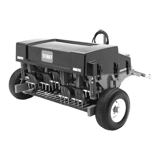
- Page 1 FORM NO. 3318-400 GB Rev A OPERATOR'S MODEL NO. 09501—60001 & OVER MANUAL ® FAIRWAY AERATOR © 1996, The Toro Company...
-
Page 2: Table Of Contents
If help concerning operation, maintenance or safety is ever needed, contact the local authorized TORO Distributor. In addition to genuine TORO replacement parts, the distributor also has optional equipment for the complete line of TORO turf care equipment. Keep your TORO all TORO. Buy genuine TORO replacement parts and accessories. -
Page 3: Safety Instructions
Safety Instructions Awareness, concern and proper training of personnel C. Do not transport the machine close to sand involved in operation, maintenance and storage of this traps, ditches, creeks or other hazards. machine are vital to your safety. Improper machine use or maintenance can result in injury or death. - Page 4 Maintenance 11. Before servicing the machine, raise the coring head, disengage power to the aerator, shift the prime mover to neutral and set the parking brake. Lift the safety/transport stands to their full upright position and lower the coring head onto the stands. Stop the engine.
-
Page 5: Safety Symbol Glossary
Symbol Glossary SAFETY ALERT GENERAL HAZARD CRUSHING OF CRUSHING OF CUTTING OF CUTTING OF FOOT CRUSHING OR SYMBOL SAFETY ALERT WHOLE BODY, FINGERS OR HAND, FINGERS OR HAND PUNCTURE OF FOOT, APPLIED FROM FORCE APPLIED CORING HEAD ABOVE FROM SIDE WHOLE BODY ENTANGLEMENT, FINGERS OR HAND THROWN OR FLYING... - Page 6 ON/START OFF/STOP FAST SLOW CONTINUOUS ENGINE START ENGINE STOP VARIABLE, LINEAR 1 INCH (25mm) PARK UNLEADED FUEL FUEL TANK FILL LOCK UNLOCK CORING HEAD ALWAYS HAVE CORING HE LINE FULLY UP FOR TRANSPOR FULLY DOWN FOR CORING TRACTION DRIVE MANUAL CHOCK WHEELS IN PARKED POSITION, ALWAYS FORK FROM FRONT OR REAR LEVER OPERATION...
-
Page 7: Specifications
Specifications Types: Three-wheel, PTO-driven, tow-behind deep cor- Hydraulic Hose: 9.5 mm x 304.8 cm (3/8 x 120 in.), SAE ing turf/fairway aerator. 100R1A. Tractor Requirements: 26–33.6 kw (35–45 hp) @ Quick Coupler: 1/2 - 14 FE NPT ends. Meets ISO, SAE, standard power take-off speeds. - Page 8 Dimensions: Length—279.4 cm (110 in.).Width—228.6 cm (90 in.) [from outside of tires].Height—11.8 cm (44 in.).Weight—1350 kg (2975 lb).Wheel Base—113.03 cm (44 1/2 in.) with 10.8 cm (4 1/4 in.) rearward castor. Standard Equipment: Equipped with either two 7/8 in. or six 3/4 in.
-
Page 9: Before Operating
Before Operating Adjusting Tine Penetration To adjust equally on both sides: Loosen the capscrews securing both height adjusters (Fig. 1). Raise the adjusters until the bolt bottoms out in the slot. Maximum penetration depth of 12.7 cm (5 in.) for 7/8 in. - Page 10 Tractor Hitch Requirements (Preferred) A = 14” = End of PTO to hitch pin hole B = 1” = Horizontal distance from hitch pin to tire C = 15” = Height of hitch D = 8” Top of hitch to center line of PTO E = 4”...
- Page 11 GEARS Driver Driven Sec./30.5 INCREASING HOLE 42.3 SPACING 39.9 37.7 35.5 Optimum vehicle speed 33.6 (Bold Print)) 31.7 DECREASING HOLE 30.0 SPACING 28.3 26.7 25.2 23.8 Important: Driver and driven gears selected must combine to add up to 70. Gear Installation: Remove the pick-off gear case cover (Fig.
- Page 12 Important: Never exceed 540 tractor PTO rpm or you may damage the aerator. In the direction of travel, measure the distance between tine holes (one tine stroke hole to another). The distance should 7/8 in. tines–14.6 to 15.2 mm (5-3/4 to 6 in.). 3/4 in.
-
Page 13: Operation
Operation Training Period tractor and aerator components and the drive line is not compressed below 92 cm (36 1/4 in.), nor extended over 127 cm (50 in.). Otherwise, the hitch hose or drive line Before first using the aerator, use a clear area to practice could be damaged. -
Page 14: Inspection And Clean-Up After Use
IMPORTANT: Do not exceed transport speeds of 24 km/hr (15 mph) or the tires may fail. Inspection and Clean-up After Use After use, thoroughly wash the machine with a garden hose without a nozzle to avoid seal contamination and bearing dam- age from excessive pressure. -
Page 15: Operating Tips
check, major component failure may result. Do not operate the aerator until a mechanic has completed this process. Operating Tips Gradually engage the PTO at low engine speed and throttle up to 540 RPM before lowering the coring head. Make very gradual turns when aerating. Never make sharp turns with the PTO engaged. - Page 16 Figure 16 Figure 14 Figure 15 Check the Reservoir Level After every25 hours of operation, or seasonally, whichever comes first, check the level of in the reservoir. With the machine on a level surface, remove the oil fill plug and dipstick assembly from the reservoir (Fig 17). The oil level should be between the two marks on the dip- stick.
- Page 17 operating level, add approximately 9 liters. NOTE: Drain plugs are also at the bottom of each (3) gear case. Check the Right-Angle Gear Case Oil Level After every 25 hours of operation, or seasonally, whichever comes first, check the level in the right-angle gear case (Fig. 19) With the machine on a levels surface, remove the oil fill plug.
-
Page 18: Maintenance
Maintenance Checking Stomper Assemblies Within the first five hours of initial machine operation, and after every 25 hours of operation thereafter, all stomper assemblies must be checked for excessive lateral play. This must be done or major machine component failure may result. Grasp each stomper assembly at the bottom and try to move the assembly laterally in each direction (Fig 23). - Page 19 Aerator Gear Case Timing Tips If disassembly of the aerator drive system is required for mainte- nance, the unit will need to be retimed to ensure n balance, equal loading of the tine arms and optimum hole quality. There are two separate procedures to properly tine the aerator gear cases.