Advertisement
RTN 380H V100R008
Quick Installation Guide
Issue: 03
Date: 2018-03-10
Copyright © Huawei Technologies Co., Ltd. 2018. All rights reserved.
No part of this document may be reproduced or transmitted in any form or by any means without prior
written consent of Huawei Technologies Co., Ltd.
Huawei Technologies Co., Ltd.
Address:
Huawei Industrial Base
Bantian, Longgang
Shenzhen 518129
People's Republic of China
Website:
http://www.huawei.com
Email:
support@huawei.com
RTN 380H packing list
No.
Item
1
2
3
4
5
6
7
Description
RTN 380H module
Auxiliary material package
7.6 mm-wide outdoor binding strap
3.6 mm-wide outdoor binding strap
Waterproof labels for outdoor cables
Engineering labels for indoor cables
Waterproof tape
01
Advertisement
Table of Contents

Related Manuals for Huawei RTN 380H


Summary of Contents for Huawei RTN 380H
- Page 1 Waterproof labels for outdoor cables Engineering labels for indoor cables Copyright © Huawei Technologies Co., Ltd. 2018. All rights reserved. No part of this document may be reproduced or transmitted in any form or by any means without prior written consent of Huawei Technologies Co., Ltd.
-
Page 2: Installation Conditions
When installing RTN 380H on a rooftop upright pole, ensure that: 1. Antennas with a diameter of 0.3 m or less are used. RTN 380H can be installed on a rooftop upright pole only on the last microwave hop at the network tail. -
Page 3: Safety Precautions
• within 2 km of a medium pollution source such as a chemical, rubber, or electroplating plant The RTN 380H is usually installed in an elevated location, such as on a tower or on the roof of a building. Adhere the following guidelines for installations in •... - Page 4 Do not leave any Ethernet service cable unconnected (see Figure 1). Maintenance through WLAN, because the RTN 380H is installed at a high position. You can use the following methods to If an Ethernet service port is not in use, remove the cable from it and fasten a PG cover or protective cover onto it.
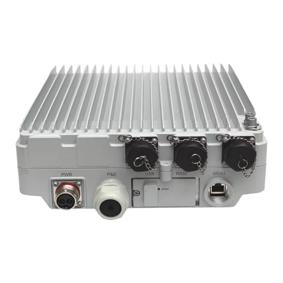
- Page 5 When the GE electrical module is used, Front view of ports the waterproof socket must also be Two types of RTN 380H are available: RTN 380H housing fitted. In addition, if the network cable MXUI5 and RTN 380H housing MXXI5. Installing these two length is no less than 2 m, a signal types of RTN 380H is the same.
- Page 6 •The recommended USB flash drive is Netac U208 with a 4 GB View A RJ45 connector capacity. Main label •If a different model or capacity is required, contact your Pin1 Pin8 Multimeter port nearest Huawei office. •The appearance of Netac U208 flash drives varies depending on the vendor. 10/11 >>...
- Page 7 The pin assignments of the P&E port on some Ethernet power supply equipment may be different from those on the RTN 380H. In this case, you need to make a network cable based on the pin Terminate one end of an outdoor network cable with an RJ45 connector assignments of the two P&E ports.
- Page 8 Terminating a Ground Cable with an OT Terminal Strip the ground cable. Mapping between the cross-sectional area of a Fit the exposed cable into the OT terminal. Crimp the OT terminal lug. cable conductor (C) and the length of an exposed cable (L1) A: OT terminal B: ground cable...
- Page 9 If an antenna with a diameter of 0.2 m, 0.3 m or 0.6 m is used in a direct mount scenario, you may install the RTN 380H on the antenna and then hoist them both into position on the tower.
- Page 10 If an antenna with a diameter of 0.2 m, 0.3 m or 0.6 m is used in a direct mount scenario, you may install the RTN 380H on the antenna and then hoist them both into position on the tower.
- Page 11 If an antenna with a diameter of 0.2 m, 0.3 m or 0.6 m is used in a direct mount scenario, you may install the RTN 380H on the antenna and then hoist them both into position on the tower.
-
Page 12: Aligning Antennas
When the local RSL reaches the maximum peak value, secure the local antenna. Connect a multimeter to the RSSI port on the RTN 380H at the local end and measure the voltage value V Adjust the remote antenna to ensure that the RSL at the local end and the RSL at the remote end reach the peak value. - Page 13 Appendix Aligning Antennas Moistureproofing the Connectors of 10GE(o), COMBO, COMBO(e) and P&E ports Relationship Between RSSI Port Voltage and Receive Signal Level Root Root 30mm Root Root 30mm 30mm 30mm COMBO(e) P&E XPIC COMBO 10GE(o) 10GE(o) Moistureproofed parts: Length between the root of XPIC/COMBO/10GE(0) The entire DC/P&E/COMBO(e)port connector and the port connector and the lower edge of the length between the root of connector and the lower edge...
-
Page 14: Important Notes
Appendix Installing the Waterproof Socket for the Outdoor Fiber Installing the Aiming Telescope Appearance of the waterproof socket Components Eye lens tube Support plate Collar Rubber washer Locking ring Shell Thread the outdoor fiber through the waterproof socket. Objective lens tube Thread the outdoor fiber through the shell, rubber washer, Remove the dustproof cap on the flange socket Prism table... - Page 15 Appendix Installing the Aiming Telescope Remove the ground terminal from Install support rob A. Fix the aiming telescope Loosen the locking ring, adjust the aiming the equipment. onto support rods. telescope to a proper position, and tighten the locking ring. Captive screws Hand wheel (Optional) Install support rob B.
- Page 16 Appendix Installing the Aiming Telescope Remove the aiming telescope and support Install the ground terminal on the equipment. robs and place them into the tool box in order. 30/31 >>...
-
Page 17: Installation Reference
Install the hybrid coupler onto the antenna. lubricant to the end face ② of the port. Vertical ① ② CAUTION After finishing the installation, hold the RTN 380H's handles with your hands and 32/33 >> turn it to check whether it is installed securely. - Page 18 3. Lead a GE cascade fiber through the waterproof socket and expose the LC/PC connector (for details, see the appendix). 2. Attach a cable tie to the network cable to prevent the PG 4. Connect the LC/PC connector to the GE(o)/COMBO port of the RTN 380H. cover from sliding down.
- Page 19 Installation Reference Installing the RTN 380H Assembling DC Power Cables Tighten the compact screw in the "+" hole, rotate the Close the wire clip and tighten the screw to compact connector 180 degrees, and tighten the compact screw the shield layer.
- Page 20 Installation Reference Installing a Signal Lightning Surge Protector When a device uses SFP GE electrical modules, it must be used with a signal lightning surge protector. Connect the outdoor network cables to the signal lightning surge protector. Signal lightning Connect the surge end of the protector to GE electrical signals and surge protector use SFP GE electrical modules to connect the protect end to the device.
- Page 21 PGND cable from the top downwards. Do not route the ground cable upwards. Identify the delivery time of an RTN 380H as follows: Identify the delivery time. Find the ESN label on the RTN 380H.
- Page 22 Installation Reference Laying out Cables Installing sign plate labels General requirements 1. Bend radius For power and PGND cables, ensure a bend radius of at least three times the cable diameter. 2. Cable binding •Bind different cables separately. Maintain an interval of at least 30 mm between cable bindings. •Bind cables securely and neatly, without damaging the cable jackets.
- Page 23 2. Forcible power supply (turn the DIP switch to the Force mode) Connection between PI and RTN 380H NOTE When the RTN 380H is installed at a high position on a tower, maintenance personnel cannot performance off-tower RTN 380H maintenance through WLAN. It is recommended to add an outdoor network cable to connect the P&E2 interface of the PI.
- Page 24 Installation Reference Installing the Outdoor Optical Splitter Loosen the reinforce screws. Open the case cover. Optional: wall-mounting 4 mm hex key Cable distribution area 3.1 Use a scribe template to determine the positions of mounting holes. Scribe pen Level Fiber routing clips Fiber fixing holes...
- Page 25 Hooks to fix hose clamps Outdoor fiber trough Hole blocks Connected to the fiber Connected to the fiber outlet Connected to the fiber outlet outlet on the standby on the main RTN 380H. on the customer equipment. RTN 380H. 48/49 >>...
- Page 26 Distribution cted GE Area Port Main RTN Connected to GE receive port on the main RTN 380H 380H Connected to GE transmit port on the main RTN 380H Standby Connected to GE receive port on the standby RTN 380H RTN 380H...
-
Page 27: Checking The Installation
Cables are not bent or twisted and the shield layer of the power cable is intact. There is a drip loop in the cable after it leaves the RTN 380H. There is a drip loop in the cable before it enters the equipment room. - Page 28 •The RTN 380H must be powered on within 24 hours after being unpacked. After waiting for 6 seconds, switch on the power supply again. •The power-off duration of the RTN 380H must not exceed 24 hour during maintenance. • Power on the equipment within 24 hours of unpacking.
- Page 29 Installation Reference Loading NE Data Installing the WLAN Module Ports within the Ports within the maintenance maintenance RSSI/NMS RSSI/NMS compartment compartment maintenance maintenance compartment compartment Connected to the Web LCT WLAN module Connected to the USB flash drive Open the RSSI/NMS maintenance compartment. Open the RSSI/NMS maintenance compartment.