Advertisement
Quick Links
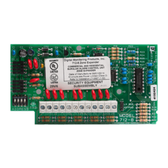
712-8 ZONE EXPANSION MODULE
Installation Guide
Figure 1: 712-8 Module
DESCRIPTION
The Model 712‑8 Zone Expansion
Module allows you to increase
the number of protection zones
available on a DMP panel. The 712‑8
provides a total of eight grounded
zones.
The zone expansion module
provides a terminal strip for zone
inputs, two 4‑pin headers for
Keypad Bus or LX‑Bus connections,
a jumper for LX‑Bus or Keypad Bus
operation, and a transmit data LED
to indicate panel communication.
Note: The 712‑8 is listed for use in
burglary applications only: No fire
circuits shall be used on this device.
Compatibility
•
XT30/XT50 Series panels
•
XR150/XR550 Series panels
What is Included?
•
One 712‑8 Zone Expansion
Module
•
Eight 1K Ohm EOL resistors
1
MOUNT THE MODULE
The module can be mounted in a DMP enclosure using the
standard 3‑hole mounting pattern. Refer to Figure 2 as needed
during installation.
MODEL
712-8
2
1.
Hold the plastic standoffs against the inside of the enclosure
side wall.
2.
Insert the included Phillips head screws from the outside of
the enclosure into the standoffs. Tighten the screws.
3.
Carefully snap the module onto the standoffs.
Figure 2: Standoff and Module Installation
WIRE THE MODULE
Use 18 to 22 gauge wire to connect the 712‑8 directly to the
Keypad Bus or use a dual‑ended 4‑wire harness to connect
directly to the LX‑Bus. This connection allows the module to
communicate with the panel and receive 12 VDC power. For more
information about wiring, refer to Wiring Specifications. Refer to
Figure 3 when wiring the module.
Connect to the LX‑Bus
1.
Place a jumper across the top two KEYPAD/LX‑ BUS pins.
2.
Connect one end of a 4‑wire harness to the top header on
the module.
3.
At the panel, connect the other end of the 4‑wire harness
to the LX‑Bus.
Connect to the Keypad Bus
1.
Place a jumper across the bottom two KEYPAD/LX‑ BUS
pins.
2.
Connect a 4‑wire harness to the top header on the module.
3.
At the panel, connect the wires to the corresponding
Keypad Bus terminals.
1
2
3
Advertisement

Related Manuals for DMP Electronics 712-8


Summary of Contents for DMP Electronics 712-8
- Page 1 712-8 ZONE EXPANSION MODULE Installation Guide MOUNT THE MODULE The module can be mounted in a DMP enclosure using the standard 3‑hole mounting pattern. Refer to Figure 2 as needed during installation. Hold the plastic standoffs against the inside of the enclosure side wall.
- Page 2 508 to 515. When connected to an XR550 panel using LX‑Bus 2, the zones respond as 608 to 615. For more information about LX‑Bus addressing, refer to Table 2. Note: Only two 712‑8 Modules can be connected to each LX‑Bus. 712-8 INSTALLATION GUIDE DIGITAL MONITORING PRODUCTS...
- Page 3 If the 712‑8 is installed in another enclosure, a DMP Model 307 Clip‑on Tamper Switch programmed as a 24‑Hour zone is required. The 712‑8 zones can only be used in Low Risk applications. Medium or High Risk applications must use panel zone inputs. 712-8 INSTALLATION GUIDE DIGITAL MONITORING PRODUCTS...
- Page 4 Increase the separation between the equipment and receiver. Connect the equipment into an outlet on a circuit different from that to which the receiver is connected. Consult the dealer or an experienced radio/TV technician for help. 712-8 ZONE Certifications FCC Part 15...
Need help?
Do you have a question about the 712-8 and is the answer not in the manual?
Questions and answers