DMP Electronics 734 Installation And Programming Manual
Weigand interface module
Hide thumbs
Also See for 734:
- Installation and programming manual (44 pages) ,
- Installation sheet (10 pages) ,
- Quick start manual (2 pages)
Table of Contents
Advertisement
Advertisement
Table of Contents

Related Manuals for DMP Electronics 734


Summary of Contents for DMP Electronics 734
- Page 1 734 Weigand Interface Module INSTALLATION AND PROGRAMMING GUIDE...
-
Page 3: Table Of Contents
User Code Position and Length ....21 Wire the Zone Terminals ........8 Site Code .............. 22 Connect a Card Reader ........10 Enter Site Code ..........23 Set the 734’s Address ........12 Number of User Code Digits ......23 No Communication with Panel ....24 Remove Keypad ..........25... - Page 4 Keypad Bus Wiring Specifications ..26 Public Card Formats ........27 Compliance Listing Specifications ..28 UL Commercial Fire ..........28 UL Access Control ..........28 ULC Commercial Burglary (XR150/XR550 Series Panels) ............28 Certifications ..........29 Underwriters Laboratory (UL Listed) ..29 Product Specifications ......30 Readers and Credentials ......
-
Page 5: About The 734
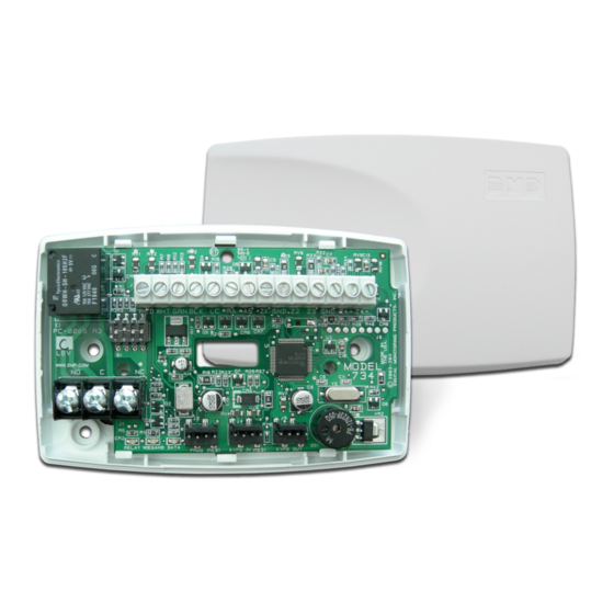
ABOUT THE 734 The 734 Wiegand Interface Module allows you to use the powerful built-in access control capability of DMP Panels. DMP panels provide access control, arming, and disarming using proximity, mag-stripe, biometric or other Wiegand-output authentication devices. Connect a 734 to a DMP panel’s keypad bus or AX-Bus to use the powerful built-in access control ™... -
Page 6: Form C Relay
KEYPAD IN AND OUT FORM C RELAY CONNECTIONS The 734’s Form C relay draws up to 35 mA of current. Refer to the NC/C/NO (Dry Contact The keypad in (KYPD IN) connection receives Relay) and the Isolation Relay sections in this and transmits data to the panel keypad bus or document for more information. -
Page 7: Pcb Features
OR AX-BUS Piezo PIEZO – RELAY WIEGAND DATA PROG KYPD IN KYPD OUT READ LED XMT LED TO OTHER KEYPAD KEYPAD BUS PROGRAMMING INDICATOR OR AX-BUS HEADER LEDS Figure 1: PCB Features Digital Monitoring Products, Inc. 734 Installation and Programming Guide... -
Page 8: Install The 734
INSTALL THE 734 MOUNT THE 734 The 734 comes in a high-impact plastic housing that you can mount directly to a wall, backboard, or other flat surface. For easy installation, the back and ends of the 734 housing have wire entrances. The back also contains multiple mounting holes that allow you to mount the 734 on a single-gang switch box. -
Page 9: Wire The Electronic Lock
WIRE THE ELECTRONIC LOCK The 734 provides a Form C (SPDT) relay for controlling locks and other electronically-controlled barriers. The three relay terminals marked NO C NC allow you to connect the device wiring to the relay for module control. -
Page 10: Isolation Relay
DC Door Strike – Power Isolation Relay 12/24 VDC – Supply Magnetic Lock Power – Supply Figure 5: Magnetic Lock with Figure 6: Door Strike with an Isolation Relay an Isolation Relay 734 Installation and Programming Guide Digital Monitoring Products, Inc. -
Page 11: Install The 333 Suppressor
Use the included 333 suppressor with the 734 Interface Module 734 to suppress any surges caused by energizing a magnetic lock or door strike. Piezo Install the 333 across the 734 C (common) – PROG KYPD IN KYPD OUT RELAY... -
Page 12: Wire The Zone Terminals
See the table below and Figure 8 for more information on wiring the zone terminals. ZONE # RECOMMENDED DEVICE RESIDENTIAL FIRE DEVICES? Any burglary device Door Contact REX (PIR or Button) Any device Table 1: 734 Zone Uses 734 Installation and Programming Guide Digital Monitoring Products, Inc. - Page 13 Zone 1 1K EOL Zone 2 1K EOL Zone 3 1K EOL 1K EOL Zone 4 RED WHT GRN BLK Z4+ Z4– Figure 8: 734 Zone Terminal Wiring Digital Monitoring Products, Inc. 734 Installation and Programming Guide...
-
Page 14: Connect A Card Reader
CONNECT A CARD READER (optional) The 734 provides direct 12/24 VDC, 200 mA output to the reader on the RED terminal connection. Figure 9 shows a reader with wire colors RED, WHT, GRN, and BLK connecting to terminals 1, 2, 3, and 4. - Page 15 Card Reader Shield Yellow Orange/Brown Black (GND) Green (Data 0) White (Data 1) Red (12/24VDC) RED WHT GRN BLK Z4+ Z4– Figure 9: Card Reader Wiring Digital Monitoring Products, Inc. 734 Installation and Programming Guide...
-
Page 16: Set The 734'S Address
SET THE 734’S ADDRESS To set the 734 address, move the DIP switches on the PCB to the appropriate positions. See the following sections, Figures 10 and 11, and Table 2 to determine how to set keypad bus or AX-Bus addresses. - Page 17 1 2 3 4 734 has a built-in four-zone expander, three extra zones will be mapped to the 734 automatically. A 734 with an address of 1 on AX500 would 1 2 3 4 1 2 3 4 1 2 3 4 1 2 3 4 represent door 501 and zones 501-504.
- Page 18 734 Address Table To set the 734 address, move the DIP switches to the appropriate positions. See Figures 10 and 11 for how to place the DIP switches for keypad bus and AX-Bus addresses. DEVICE/ DEVICE/ DEVICE/ DEVICE/ DEVICE/ DEVICE/...
-
Page 19: Program The 734
PROGRAM THE 734 When you program a 734, you can use a keypad connected to the 734 programming header and set to address 1. For 12 V applications, connect the keypad to the module using a Model 330 4-wire harness. For 24 V applications, connect the keypad to the module using a Model 330-24 4-wire programming harness with in-line resistor. -
Page 20: Initialize Confirm Option
If zone 2 restores prior to the end of the programmed time, the piezo silences. If the zone does not restore before the programmed time, the 734 ends the bypass and indicates the open or short zone condition to the panel. -
Page 21: Zone 2 Bypass Time
Selecting NO leaves the relay on when zone 2 changes state. Turning off the relay at Door Closed allows a long strike time to be automatically ended and relocks the door. The default is NO. Digital Monitoring Products, Inc. 734 Installation and Programming Guide... -
Page 22: Activate Zone 3 Request To Exit
2 bypass entry/exit timer. After the programmed number of seconds, the relay restores the door to its locked state. The 734 module provides a bypass-only option for REX on zone 3. When zone 3 OPENS from a NORMAL state, only a bypass occurs: the on-board relay does not activate. -
Page 23: Zone 3 Rex Strike Time
NO YES SPEAKER? as alarm and trouble annunciations. Select NO to turn the speaker off for all operations. This does not affect remote annunciator open collector (RA) operation. The default is NO. Digital Monitoring Products, Inc. 734 Installation and Programming Guide... -
Page 24: Custom Card Definitions
User Code Last Bit Position = 1 Position = 9 Received Received Position = 0 Length = 8 Length = 16 Position = 25 Figure 13: Wiegand Data Stream Bit Location 734 Installation and Programming Guide Digital Monitoring Products, Inc. -
Page 25: Wiegand Code Length
Press CMD to save. Default is 9. Press select area 4 to clear the user code length and enter a number between 16-40. Press CMD to save. The default is the DMP value of 16. Digital Monitoring Products, Inc. 734 Installation and Programming Guide... -
Page 26: Site Code
Press the first select key or area again to move vertically between site codes. Press the second select key or area to move horizontally between site codes. When you have selected the site code you want to change, press CMD. 734 Installation and Programming Guide Digital Monitoring Products, Inc. -
Page 27: Enter Site Code
NUMBER OF USER CODE DIGITS NO OF USER CODE The 734 module recognizes user codes from 4-12 digits long. Press DIGITS: any select key or area to enter a user code digit length. This number must match the user code number length being programmed in the panel. -
Page 28: No Communication With Panel
Press the first select key or area to choose LAST (Keep Last State) NO COMM WITH PNL — The relay remains in the same state and does not change when LAST communication is lost. 734 Installation and Programming Guide Digital Monitoring Products, Inc. -
Page 29: Remove Keypad
After five seconds, the 734N module piezo continually sounds if the keypad remains connected and programming is finished. Remove the keypad harness to disconnect the keypad from the 734N module and silence the alarm. Digital Monitoring Products, Inc. 734 Installation and Programming Guide... -
Page 30: Keypad Bus Wiring Specifications
When voltage is too low, the devices cannot operate properly. For additional information refer to the panel's Installation Guide, the 710 Installation Sheet (LT-0310), and/or the LX-Bus/Keypad Bus Wiring Application Note (LT-2031). 734 Installation and Programming Guide Digital Monitoring Products, Inc. -
Page 31: Public Card Formats
CODE CODE LENGTH POSITION LENGTH POSITION LENGTH DIGITS H10301 26 BIT H10302 37 BIT W/FAC H10304 37 BIT W/O FAC FARPOINTE 39 BIT CORPORATE 1000 35 BIT CORPORATE 1000 48 BIT Digital Monitoring Products, Inc. 734 Installation and Programming Guide... -
Page 32: Compliance Listing Specifications
ULC COMMERCIAL BURGLARY (XR150/XR550 SERIES PANELS) When using the zones of the 734 in a listed application, place the module in a listed enclosure and connect a DMP Model 307 Clip-on Tamper Switch to the enclosure programmed as a 24-Hour zone. -
Page 33: Certifications
Central Station Burglar-Alarm Units ANSI/UL 864 Fire Protective Signaling ANSI/UL 985 Household Fire-warning ULC S304 Central And Monitoring Station Burglar Alarm ULC/ORD-C1076 Proprietary Burglar ULC Subject-C1023 Household Burglar ULC S545 Household Fire Digital Monitoring Products, Inc. 734 Installation and Programming Guide... -
Page 34: Product Specifications
Alarm 260 mA (Includes 200 mA for proximity reader) Form C Relay 35 mA at 12/24 VDC Zones 5 VDC, 2 mA max Dimensions 4.5 W x 2.75 H x 1.75 D in 11.43 W x 7 H x 4.45 D cm Weight 5.6 oz .16 kg 734 Installation and Programming Guide Digital Monitoring Products, Inc. -
Page 35: Readers And Credentials
PROXPOINT® PLUS 1346 PROXKEY III® PROXIMITY READER ACCESS DEVICE PP-5355 PROXPRO PROXIMITY 1351 PROXPASS® READER WITH KEYPAD PR-5455 PROXPRO® II PROXIMITY 1386 ISOPROX II® CARD READER TL-5395 THINLINE II® PROXIMITY READER Digital Monitoring Products, Inc. 734 Installation and Programming Guide... - Page 36 FARPOINTE IMAGEABLE READER SMARTCARD DELTA5.3 FARPOINTE SMARTCARD FARPOINTE MIFARE® READER DESFIRE® EV1 SMARTCARD DELTA6.4 FARPOINTE SMARTCARD READER DK1-3 FARPOINTE KEY FOB SMARTCARD *Delta Proximity Readers and Credentials not evaluated by UL. 734 Installation and Programming Guide Digital Monitoring Products, Inc.
- Page 40 LT-0737C 18514 1.07 © 2018 Digital Monitoring Products, Inc.
Need help?
Do you have a question about the 734 and is the answer not in the manual?
Questions and answers