DMP Electronics 734 Installation And Programming Manual
Wiegand interface module
Hide thumbs
Also See for 734:
- Installation and programming manual (40 pages) ,
- Installation sheet (10 pages) ,
- Quick start manual (2 pages)
Table of Contents
Advertisement
Quick Links
Advertisement
Table of Contents

Related Manuals for DMP Electronics 734


Summary of Contents for DMP Electronics 734
- Page 1 734 Wiegand Interface Module INSTALLATION AND PROGRAMMING GUIDE...
-
Page 3: Table Of Contents
TABLE OF CONTENTS About the 734 ..........1 Program the 734 ........17 Power Supply ............1 Program Start Display ........18 Zone Terminals ............1 Initialization Option ...........18 Annunciators ............1 Initialize Confirm Option .........18 Indicator LEDs ............1 Activate Zone 2 Bypass ........19 Form C Relay ............ - Page 4 Keypad Bus Wiring Specifications ..30 Public Card Formats ........ 31 Compliance Listing Specifications ..32 UL Commercial Fire ..........32 UL Access Control ..........32 ULC Commercial Burglary (XR150/XR550 Series Panels) ............33 Certifications ..........34 Underwriters Laboratory (UL Listed) ..34 Product Specifications ......35 Readers and Credentials ......
-
Page 5: About The 734
DMP Panels. DMP panels provide access control, arming, and disarming using proximity, mag‑stripe, biometric, or other Wiegand‑output authentication devices. Connect a 734 to a DMP panel’s keypad bus or AX‑Bus™ to use the powerful built‑in access control capability of DMP panels. The 734 includes the following features:... -
Page 6: Form C Relay
Programming can be supported. XR150 Series panels support completed using a keypad connected up to 8 devices. XR550 Series panels to the 734 or from XR150/XR550 Series support up to 16 devices. When using the panels. AX‑Buses with XR550 devices, you can have 32 doors, expandable to 96. -
Page 7: Pcb Features
AX‑Bus Piezo Piezo – RELAY WIEGAND DATA PROG KYPD IN KYPD OUT READ LED XMT LED To Other Keypad Keypad Bus Programming or AX‑Bus Indicator Header LEDs Figure 1: PCB Features Digital Monitoring Products, Inc. 734 Installation and Programming Guide... -
Page 8: Install The 734
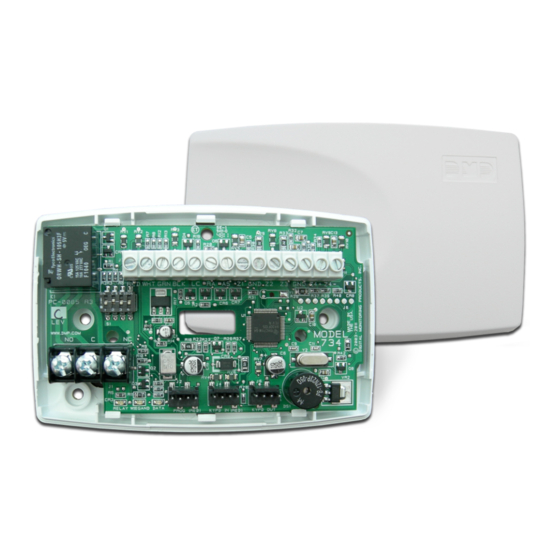
The module comes in a high‑impact plastic housing that you can mount directly to a wall, backboard, or other flat surface. For easy installation, the back and ends of the 734 housing have wire entrances. The back also contains multiple mounting holes that allow you to mount the module on a single‑gang switch box. -
Page 9: Wire The Magnetic Lock
Wire the Magnetic Lock The 734 provides a Form C (SPDT) relay for controlling locks and other electronically‑controlled barriers. The three relay terminals marked NO C NC allow you to connect the device wiring to the relay for module control. - Page 10 Install a dual‑connector harness to allow connection to other devices up to the maximum number of devices supported. When the 734 is powered from 24 VDC, do not connect devices to KYPD OUT header. Status LEDs The 734 board contains three status LEDs.
-
Page 11: Isolation Relay (Optional)
12/24 VDC DC Door Strike – Power Isolation Relay 12/24 VDC – Supply Magnetic Lock Power – Supply Figure 5: Magnetic Lock with an Isolation Figure 6: Door Strike with an Isolation Relay Relay Digital Monitoring Products, Inc. 734 Installation and Programming Guide... -
Page 12: Install The 333 Suppressor
Install the 333 Suppressor Use the included 333 suppressor with 734 Interface Module the 734 to suppress any surges caused by energizing a magnetic lock or door Piezo strike. – PROG KYPD IN KYPD OUT RELAY WIEGAND DATA READ LED... -
Page 13: Wire The Zone Terminals
Use the supplied 311 1K Ohm End‑of‑Line (EOL) resistors on each zone. Refer to the panel programming guide for programming instructions. See Table 1 and Figure 8 for more information on wiring the zone terminals. Digital Monitoring Products, Inc. 734 Installation and Programming Guide... - Page 14 1K EOL be wired normally closed with an Zone 3 1K EOL in-line 1K Ohm resistor 1K EOL Zone 4 RED WHT GRN BLK Z4+ Z4– Figure 8: 734 Zone Terminal Wiring 734 Installation and Programming Guide Digital Monitoring Products, Inc.
-
Page 15: Connect A Card Reader (Optional)
Connect a Card Reader (optional) The 734 provides direct 12/24 VDC, 200 mA output to the reader on the Red terminal connection. Figure 9 shows a reader with wire colors RED, WHT, GRN, and BLK connecting to terminals 1, 2, 3, and 4. - Page 16 SYSTEM ON or ALL SYSTEM ON. Connect a wire from the AS Terminal to an armed status indicator. 734 Installation and Programming Guide Digital Monitoring Products, Inc.
- Page 17 Card Reader Shield Yellow Orange/Brown Black (GND) Green (Data 0) White (Data 1) Red (12/24VDC) RED WHT GRN BLK Z4+ Z4– Figure 9: Card Reader Wiring Digital Monitoring Products, Inc. 734 Installation and Programming Guide...
-
Page 18: Set The 734 Address
Set the 734 Address To set the 734 address, move the DIP switches on the PCB to the appropriate positions. See the following sections, Figures 10 and 11, and Table 2 to determine how to set keypad bus or AX‑Bus addresses. - Page 19 1 2 3 4 1 2 3 4 1 2 3 4 automatically. A 734 with an address of 1 on AX500 would represent door 501 and zones 501‑504. A 1 2 3 4 1 2 3 4 1 2 3 4...
- Page 20 734 Address Table To set the 734 address, move the DIP switches to the appropriate positions. See Figures 10 and 11 for how to place the DIP switches for keypad bus and AX‑Bus addresses. DEVICE/ DEVICE/ DEVICE/ DEVICE/ DEVICE/ DEVICE/...
-
Page 21: Program The 734
734 from the panel, all future programming should be performed through the panel. The panel’s programming overrides any programming performed from a keypad connected to the 734. While the 734 is in programming mode, it will not be able to communicate with the panel. -
Page 22: Program Start Display
Program Start Display 734 PROGRAMMING When you connect the keypad to the 734 module, the VER VVV MM/DD/YY version number and release date display. Press CMD to enter the Programming Menu. Initialization Option INITIALIZE ALL? These options can set the 734 module programming memory NO YES back to factory defaults. -
Page 23: Activate Zone 2 Bypass
NO YES NO allows standard zone operation on zone 2. The default is If the door being released by the 734 module is protected (contact installed), a programmable bypass entry/exit timer can be provided by connecting its contact wiring to the 734 module zone 2. -
Page 24: Zone 2 Bypass Time
Selecting NO leaves the relay on when zone 2 changes state. Turning off the relay allows a long strike time to be automatically ended upon zone 2 change and relocks the door. The default is NO. 734 Installation and Programming Guide Digital Monitoring Products, Inc. -
Page 25: Activate Zone 3 Request To Exit
Activate Bypass Only Wire zone 3 as normally closed with an in‑line 1K Ohm resistor. When zone 3 opens from a normal state, only a bypass occurs: the onboard relay does not activate. Digital Monitoring Products, Inc. 734 Installation and Programming Guide... -
Page 26: Zone 3 Rex Strike Time
ZN 3 REX TIME. No user code information is sent to the panel. The menu advances to NO COMM WITH PNL. The default card format is DMP. 734 Installation and Programming Guide Digital Monitoring Products, Inc. -
Page 27: Custom Card Definitions
2‑8. See Public Card Formats for some publicly available card formats that can be used with the 734. Other private or custom formats may also be compatible. Please contact the credential supplier or manufacturer for the bit structure. -
Page 28: Format Name
Position = 9 Received Received Length = 8 Length = 16 Position = 25 Position = 0 In this example the Wiegand Code Length = 26 bits. Figure 13: Wiegand Data Stream Bit Location 734 Installation and Programming Guide Digital Monitoring Products, Inc. -
Page 29: Site Code Position And Length
0‑255. Press CMD to save. Default is 9. Press select area 4 to clear the user code length and enter a number between 16‑64. Press CMD to save. Default is 16. Digital Monitoring Products, Inc. 734 Installation and Programming Guide... -
Page 30: Require Site Code
In the keypad display, enter site code 1 and press CMD. The display will ask for site code 2 followed by site code 3 and so on. When you have selected the site code you want to change, press CMD. 734 Installation and Programming Guide Digital Monitoring Products, Inc. -
Page 31: Number Of User Code Digits
Number of User Code Digits NO OF USER CODE The 734 module recognizes user codes from 4‑12 digits long. DIGITS: Press any top row select key or area to enter a user code digit length. This number must match the user code number length being programmed in the panel. -
Page 32: No Communication With Panel
Press the first select key or area to choose LAST (Keep Last NO COMM WITH PNL State). The relay remains in the same state and does not LAST change when communication is lost. 734 Installation and Programming Guide Digital Monitoring Products, Inc. -
Page 33: Remove Keypad
Remove Keypad REMOVE KEYPAD The REMOVE KEYPAD option continually displays with no time out while the keypad remains connected to the 734 module after programming is finished. After five seconds, the 734 module piezo continually sounds if the keypad remains connected and programming is finished. -
Page 34: Keypad Bus Wiring Specifications
When voltage is too low, the devices cannot operate properly. For additional information refer to the panel’s Installation Guide or the 710 Installation Sheet (LT‑0310). 734 Installation and Programming Guide Digital Monitoring Products, Inc. -
Page 35: Public Card Formats
CODE CODE LENGTH POSITION LENGTH POSITION LENGTH DIGITS H10301 26 BIT H10302 37 BIT W/FAC H10304 37 BIT W/O FAC FARPOINTE 39 BIT CORPORATE 1000 35 BIT CORPORATE 1000 48 BIT Digital Monitoring Products, Inc. 734 Installation and Programming Guide... -
Page 36: Compliance Listing Specifications
Authority Having Jurisdiction (AHJ). This system is not intended to be used in place of listed panic hardware. The power supply must be a listed commercial burglary/household fire, power limited, Class 2 with a compatible voltage range for the product. The 734 requires a 12 or 24 VDC power source. 734 Installation and Programming Guide... -
Page 37: Ulc Commercial Burglary (Xr150/Xr550 Series Panels)
ULC Commercial Burglary (XR150/XR550 Series Panels) When using the zones of the 734 in a listed application, place the module in a listed enclosure and connect a DMP Model 307 Clip‑on Tamper Switch to the enclosure programmed as a 24‑Hour zone. -
Page 38: Certifications
Central Station Burglar‑Alarm Units ANSI/UL 864 Fire Protective Signaling ANSI/UL 985 Household Fire‑warning ULC S304 Central And Monitoring Station Burglar Alarm ULC/ORD‑C1076 Proprietary Burglar ULC Subject‑C1023 Household Burglar ULC S545 Household Fire 734 Installation and Programming Guide Digital Monitoring Products, Inc. -
Page 39: Product Specifications
Alarm 260 mA (Includes 200 mA for proximity reader) Form C Relay 35 mA at 12/24 VDC Zones 5 VDC, 2 mA max Dimensions 4.5 W x 2.75 H x 1.75 D in 11.43 W x 7 H x 4.45 D cm Weight 5.6 oz 0.16 kg Digital Monitoring Products, Inc. 734 Installation and Programming Guide... -
Page 40: Readers And Credentials
PROXPOINT® PLUS 1346 PROXKEY III® PROXIMITY READER ACCESS DEVICE PP‑5355 PROXPRO PROXIMITY 1351 PROXPASS® READER WITH KEYPAD PR‑5455 PROXPRO® II PROXIMITY 1386 ISOPROX II® CARD READER TL‑5395 THINLINE II® PROXIMITY READER 734 Installation and Programming Guide Digital Monitoring Products, Inc. - Page 41 FARPOINTE IMAGEABLE READER SMARTCARD DELTA5.3 FARPOINTE SMARTCARD FARPOINTE MIFARE® READER DESFIRE® EV1 SMARTCARD DELTA6.4 FARPOINTE SMARTCARD READER DK1‑3 FARPOINTE KEY FOB SMARTCARD *Delta Proximity Readers and Credentials not evaluated by UL. Digital Monitoring Products, Inc. 734 Installation and Programming Guide...
- Page 42 734 Installation and Programming Guide Digital Monitoring Products, Inc.
- Page 43 Digital Monitoring Products, Inc. 734 Installation and Programming Guide...
- Page 44 LT-0737 19345 1.07 © 2019 Digital Monitoring Products, Inc.
Need help?
Do you have a question about the 734 and is the answer not in the manual?
Questions and answers