Table of Contents
Advertisement
Advertisement
Table of Contents

Related Manuals for Culligan High Efficiency 1.5 Twin Series


Summary of Contents for Culligan High Efficiency 1.5 Twin Series
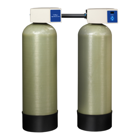
- Page 1 Cat. No. 01024821 Rev. I 05/09/17 DCO # 017180 Installation, Operation, and Service Instructions with Parts Lists CULLIGAN ® High Efficiency 1.5 Twin Water Softener Featuring the Culligan Smart Controller™ ® Models from 2012 ©2017 Culligan International Com pa ny...
- Page 2 Products manufactured and marketed by Culligan International Company (Culligan) and its affiliates are protected by patents issued or pending in the United States and other countries. Culligan reserves the right to change the specifications referred to in this literature at any time without prior notice. Culligan, Aqua-Sensor, Tripl-Hull, and SoftMinder are trademarks of Culligan International Company or its affiliates.
-
Page 3: Table Of Contents
Installation, Operation, and Service Instructions with Parts Lists Culligan High Efficiency 1.5 Twin ® Water Softener Featuring the Culligan Smart Controller™ ® Models from 2012 Contents Introduction ................ Appendix B Flow Data..........Basic Principles ..............Appendix C Data Port Output........ - Page 4 Services Water Testing Made Easy. Culligan’s Analytical Laboratory provides its customers with quality water analysis using EPA approved methods. Our Analytical Laboratory is certified by the State of Illinois EPA, to be compliant with the National Environmental Laboratory Accreditation Conference (NELAC) standards. In addition to Illinois chemical certification, our Analytical Laboratory is certified to perform coliform and E.
-
Page 5: Introduction
® device and its capabilities. Culligan® High Efficiency 1.5 Twin water softener systems are designed to meet the needs of applications for high quality water. This manual contains important information about the unit, including information needed for installation, operating, and maintenance procedures. A troubleshooting section provides a guide for quick and accurate problem solving. -
Page 6: Basic Principles
The regeneration process for your commercial water softener is controlled automatically either on a predetermined time, volume, or external signal basis through the use of the Culligan Smart Controller with optional flow sensor. See the Instal- lation chapter for further information. The regeneration process can also be initiated manually by the operator as required. -
Page 7: Performance Specifications
They include: An operating water pressure between 20 and 125 psi (138-862 kPa). If water pressure is greater than 80 psi, Culligan recommends following the IAPMO Uniform Plumbing code section 806.2 by installing a Pressure Regulating Valve before the system. -
Page 8: Installation
Screw the control assembly onto the empty media tank until it seats. Mark the front of the tank, then remove the control assembly. Cat. No. 01024821 Culligan® High Efficiency 1.5 Twin Water Softener... - Page 9 Install Distribution System CAUTION! Do not attempt to use any distribution part that is damaged. Doing so may create operational problems and/or create a substantial risk of consequential damage not covered by the product warranty. Mark flush with tank opening Media Tank Remove distributor and cut square on mark Distributor...
- Page 10 Clean tank threads, remove tape and check for any foriegn materials NOTE Minimize the amount of water added until final positioning of the tank with the control valve mounted. Cullex Cullsan Figure 2. Cat. No. 01024821 Culligan® High Efficiency 1.5 Twin Water Softener...
- Page 11 Mount the Control Valve Install the inlet disperser to the Lubricate the outlet distributor O-ring bottom of the control valve. with a silicone-based lubricant. Install the tank adapter o-ring above the valve’s threads. Do not lubricate, but can be wetted with water.
- Page 12 Do not install a vacu- um breaker on the drain line. Use a vacuum breaker, such as Culligan 00401584 or 01003701. Multi-tank systems will require at least one vacuum breaker per tank.
- Page 13 Suggested Piping Installations The piping layouts below depict a traditional three-valve bypass. Culligan also offers an optional bypass valve that con- nects directly to the inlet and outlet of the water softener. NOTE Interconnecting pipe and fittings, bypass valves, and isolation valves are not supplied.
- Page 14 DO NOT make a direct connection to the drain. Provide an air gap of at least four times the diameter of the drain pipe or conform to local sanitation codes and to permit the observation of drain flow. Cat. No. 01024821 Culligan® High Efficiency 1.5 Twin Water Softener...
- Page 15 Drain Line Flow Control Replacement Refer to Table 4, Figure 8, and the instructions below to replace the drain line flow control. Remove the cover by releasing the cover fastener from the control valve. See Figure 6 and Figure 7. Remove the drain clip and pull off the drain elbow.
- Page 16 Attach the cover fastener onto the control valve. See Figure 11. Figure 9. Cover fastener clip. Figure 10. Reattaching the HE softener cover. Push Down Into Place Cover Fastener Figure 11. Reattaching the cover fastener. Cat. No. 01024821 Culligan® High Efficiency 1.5 Twin Water Softener...
- Page 17 GBE Programming for Commercial Softeners and Filters, except HF xN Manual (P/N 01027295) to update the Dial-a-Softness setting. Straight-Through Adapter Shipped with each softener is a Culligan® straight-through adapter, which is used to connect the softener to the plumbing system. CAUTION!
- Page 18 Lubricate all O-rings on the couplings/meter with silicone lubricant. NOTE The Low Flow Meter has a white dot on the connec- tion for the wire harness. Meter Body Coupling Bypass Figure 14. Bypass valve assembly. Cat. No. 01024821 Culligan® High Efficiency 1.5 Twin Water Softener...
- Page 19 Optional Bypass Valve Operation To bypass, turn the blue knob clockwise (see directional arrow on end of knob) until the knob stops as shown. DO NOT OVERTIGHTEN! (Figure 15). To return to service, turn the blue knob counter-clockwise (see directional arrow on the end of knob) until the knob stops as shown.
- Page 20 If multiple softeners will be drawing brine from the same tank, connect the brine tubing from the brine fitting on each valve to a union tee. (P/N 00401574, supplied with small parts pack) Cat. No. 01024821 Culligan® High Efficiency 1.5 Twin Water Softener...
- Page 21 Circuit Board Connections The 24V power supply and flow meter wire harness is already connected to the circuit board. If no other circuit board connections are required proceed to the First Time Setup. Refer to the instructions below and Figure 17 to Figure 30 connecting accessories, including the Aqua-Sensor probe wire harness, to the circuit board.
- Page 22 Place the harness and fitting through the port. Tighten the nut on the interior of the enclosure. Attach the connector to the appropriate location on the HE circuit board. See “Electrical Schematic” on page Cat. No. 01024821 Culligan® High Efficiency 1.5 Twin Water Softener...
- Page 23 Installing Accessory Connections The HE 1.5 Controller enclosure has several portals to allow connections to HE accessories. Each connection portal is molded into the controller enclosure. If the portal is not already opened and/or plugged, it may be opened by pushing a sharp object (screwdriver or knife) through the plastic.
- Page 24 Verify wiring from the terminals to circuit board are correct before applying power to the control. 24V power must not be applied to the 2.5 VAC terminals. Connecting 24V to the 2.5 VAC connection on the circuit board will damage the circuit board. Cat. No. 01024821 Culligan® High Efficiency 1.5 Twin Water Softener...
- Page 25 NOTE The wire connectors must be connected to the circuit board properly. The wires must exit the plug-in connector opposite of the raised white base of the circuit board connector. Failure to properly connect any of the connectors will result in a malfunction of the circuit board operation. 13.
- Page 26 Failure to do so can result in, at a minimum, damaging the GBE circuit boards. Culligan STRONGLY RECOMMENDS that every GBE circuit board be provided with its own individual power transformer as shown in Figure 27.
- Page 27 CORRECT FOUR INDIVIDUAL TRANSFORMERS NO NEED TO MATCH POLARITY BASE BOARD BASE BOARD BASE BOARD MODEM MODEM MODEM BOARD BOARD BOARD RF BOARD RF BOARD RF BOARD RJ11 RJ11 RJ11 PHONE PHONE PHONE AUXILARY BOARD AUXILARY BOARD AUXILARY BOARD ISOLATION ISOLATION ISOLATION RELAY...
- Page 28 Refer to the GBE Programming for Commercial Softeners and Filters, except HF xN Manual (P/N 01027295) for programming information. This manual can be obtained from your local dealer, on CPort (www.cport.culligan.com) under the Technical Service Tab or on the Service Tech App. Cat. No. 01024821 Culligan® High Efficiency 1.5 Twin Water Softener...
-
Page 29: Smart Controller Circuit Board Layout
Smart Controller Circuit Board Layout Smart Controller Circuit Board Layout–Front OLED Display Battery CR2032 (Postitive Side Up) Pull protective tab before activating power to activate the battery Keypad connector Figure 31. Smart Controller circuit board layout, front view. Smart Controller Circuit Board Layout–Back Optional AUX 5 Relay Board Connection Data Port PLC Output... -
Page 30: Electrical Schematic
Motor from Lead Cable from Tank Lead Tank 2.5V Smart Brine Tank Probe Power Supply Flow Meter from Second Tank Motor from Second Tank Gearbox Position Sensor on Second Tank Cat. No. 01024821 Culligan® High Efficiency 1.5 Twin Water Softener... -
Page 31: Installing Accessories
Refer to GBE Programming for Commercial Soft- eners and Filters (except for HFxN) Manual (P/N 01027295) for programming information. This manual can be obtained from your local dealer, CPort (www.cport.culligan.com) under the Technical Service or on the Service Tech App. - Page 32 Figure 36. Auxiliary board activation timing. Refer to GBE Programming for Commercial Softeners and Filters (except for HFxN) Manual (P/N 01027295) for program- ming information. This manual can be obtained from your local dealer, CPort (www.cport.culligan.com) under the Techni- EXAMPLE cal Service Tab or on the Service Tech App.
- Page 33 GBE board. Refer to GBE Programming for Commercial Softeners and Filters (except for HFxN) Manual (P/N 01027295) for program- ming information. This manual can be obtained from your local dealer, CPort (www.cport.culligan.com) under the Techni- cal Service Tab or on the Service Tech App.
- Page 34 Program the remote and main monitor units using the instructions found in the GBE Programming for Commercial Softeners and Filters (except for HFxN) Manual (P/N 01027295). This manual can be obtained from your local dealer, Cport (www.cport.culligan.com) under the Technical Service Tab or the Service Tech App.
- Page 35 Modem NOTE The modem can be installed into either the back of the main controller or the back of the remote con- trol board. The functionality of the modem is the same in either installation. Unplug the wireless remote before installing the modem into the back of the GBE board or the back of the remote.
- Page 36 Back of remote board. Refer to the GBE Programming for Commercial Softeners and Filters, except HF xN Manual (P/N 01027295) for pro- gramming information. This manual can be obtained from your local dealer, on CPort (www.cport.culligan.com) under the Technical Service Tab or on the Service Tech App.
-
Page 37: Final Startup
(see the GBE Programming for Commerical Softeners and Filters, except for HF xN Manual (P/N 01027295)). NOTE This manual can be obtained from your local dealer, on CPort (www.cport.culligan.com) under the Technical Service Tab or on the Service Tech App. - Page 38 11.6 61.7 20.6 61.7 20.6 34.7 61.7 15.4 61.7 15.4 34.7 61.7 12.3 61.7 12.3 61.7 61.7 Chart shows max salt dosage for dry storage in total lbs and lbs/ft³ Cat. No. 01024821 Culligan® High Efficiency 1.5 Twin Water Softener...
- Page 39 To use Table 8 locate the resin volume of the softener model along the left side of the table. Select a 6, 10 or 15 pound/ cubic foot of resin salt dosage amount. Continue reading the table to the right until you find a brine system that provides the salt storage characteristics desired.
- Page 40 Cat. No. 01024821 Culligan® High Efficiency 1.5 Twin Water Softener...
- Page 41 Hazard from toxic fumes! Chlorine bleach and common iron control chemicals may generate toxic fumes when mixed. If the unit uses Culligan® Sofner-gard® or other compounds containing sodium hydrosulfate, sodium bisulfate, or any other reducing agent, disconnect the device feeding the chemical(s) and manually regenerate the unit before sanitizing.
- Page 42 Use only mild soap and warm water to clean the exterior of the unit. Never use harsh abrasive cleaners or com- pounds which contain acid or bleach. Culligan recommends Simple Green or an equivalent cleaner. Protect the conditioner and drain line from freezing temperatures.
-
Page 43: Preventive Maintenance
Suggested Preventive Maintenance Inspection Schedule The Culligan HE 1.5 Twin commercial water softener has been designed to provide a good, consistent service life. Rou- tinely inspecting the system may help avoid potentially costly breakdowns related to circumstances outside of the control of the dealer and/or user. -
Page 44: Maintenance
Refer to the GBE Programming for Commercial Softeners and Filters, except HF xN Manual (P/N 01027295) for diagnostic procedures using the Smart (GBE) Controller. This manual can be obtained from your local dealer, on CPort (www.cport.culligan.com) under the Technical Service Tab or on the Service Tech App. - Page 45 Circuit Board Remove the electrical enclosure from the control valve. Remove the electrical enclosure screw, and then gently remove the enclosure from the control. See Figure 44. Electrical Enclosure Screw Flow Meter Wire Harness 24V Power Cord (also 2.5VAC for optional Aqua-Sensor) Figure 44.
- Page 46 Once the motor is fully inserted, re-install the motor retainer rod, compartment plate, and motor wire harness. Compartment Plate Motor Motor Wire Harness Compartment Plate Screw Position Sensor Electrical Motor Retainer Enclosure Screw Position Sensor Harness Figure 47. HE 1.5 gear motor. Cat. No. 01024821 Culligan® High Efficiency 1.5 Twin Water Softener...
- Page 47 Replace the Gearbox NOTE Remove and retain the original motor when replacing only the gearbox. Remove the HE 1.5 electrical enclosure. See “Circuit Board” on page 41 to remove the electrical enclosure. Depressurize the unit (see page Disconnect the motor power wires. Remove the compartment plate by removing the compartment plate screw holding it onto the frame.
- Page 48 Reassemble by reversing the directions above. NOTE The number of the flow control should face into the valve body. Brine Connector Clips Flow Control Drain Elbow Figure 51. Brine line. Cat. No. 01024821 Culligan® High Efficiency 1.5 Twin Water Softener...
-
Page 49: Troubleshooting
Troubleshooting Drain Line Flow Control—Service Located on the drain connection of the valve, the purpose of the drain line flow control is to regulate the up flow backwash required to expand and agitate the resin in the softener. The softener will allow maximum expansion of the resin, while preventing any loss to the drain. - Page 50 Inlet manifold plugged Remove control from tank and clean inlet manifold. Check if eductor screen/nozzle are also plugged. Control plugged with foreign material bro- Clean control. ken loose from recent plumbing work. Cat. No. 01024821 Culligan® High Efficiency 1.5 Twin Water Softener...
- Page 51 Problem/Symptom Cause Solution Loss of mineral to Improper drain line flow control Ensure that the control has the proper drain line drain flow control. Air in water system Ensure that system has proper air eliminator control. Mineral to service Defective outlet manifold Replace outlet manifold Water in brine stor- Plugged drain line flow control (Unit will...
- Page 52 Refer to the GBE Programming for Commercial Softeners and Filters, except for HF xN Manual (P/N 01027295) . This manual can be obtained from your local dealer, CPort (www.cport.culligan.com) under the Technical Service Tab or on the iPad Service Tech App.
- Page 53 Flow Diagrams HE 1.5 Twin Flow Valve Piston Locations The flow valve controls the movement of untreated and treated product during downflow and upflow regeneration cycles. Figure 52 identifies each piston as installed. For example, in this cycle (downflow service), the P1 and P2/P3 valves are open;...
- Page 54 Softened Water Drain Brine Diluted Brine Tank Outlet Figure 53. Down flow regeneration—service. Service Piston Position P1–Inlet Open P2/3–Outlet Open P4–Backwash Closed P5–Rinse Closed P6–Bypass Closed Brine Piston Closed PR–Refill Closed Cat. No. 01024821 Culligan® High Efficiency 1.5 Twin Water Softener...
- Page 55 Backwash Raw water is directed down the center of the manifold, up through the resin, out the top of the tank to drain. The water to drain should be hard. Tank Inlet Drain Water Brine Piston Brine Tank Hard Water Softened Water Drain Brine...
- Page 56 Brine Diluted Brine Tank Outlet Figure 55. Down flow regeneration—brine draw. Brine Draw Piston Position P1–Inlet Closed P2/3–Outlet Closed P4–Backwash Closed P5–Rinse Open P6–Bypass Open Brine Piston Open PR–Refill Closed Cat. No. 01024821 Culligan® High Efficiency 1.5 Twin Water Softener...
- Page 57 Slow Rinse Raw water is directed from the inlet through the nozzle and into the throat. A vacuum is created but the brine valve has seated, so no brine is educted. The raw water enters the mineral tank, passes through the resin, up the manifold and to the drain.
- Page 58 Brine Diluted Brine Tank Outlet Figure 57. Down flow regeneration—fast rinse. Fast Rinse Piston Position P1–Inlet Open P2/3–Outlet Closed P4–Backwash Closed P5–Rinse Open P6–Bypass Open Brine Piston Closed PR–Refill Closed Cat. No. 01024821 Culligan® High Efficiency 1.5 Twin Water Softener...
- Page 59 Refill To make the brine, water flows into the salt storage area during the fill stage. Fill cycle length depends on the salt dosage. Use soft water for refill. Tank Inlet Drain Water Brine Piston Soft Water to Fill Brine Tank Brine Tank Hard Water...
- Page 60 Softened Water Drain Brine Diluted Brine Tank Outlet Figure 59. Down flow regeneration—bypass. Bypass Piston Position P1–Inlet Closed P2/3–Outlet Closed P4–Backwash Closed P5–Rinse Closed P6–Bypass Open Brine Piston Closed PR–Refill Closed Cat. No. 01024821 Culligan® High Efficiency 1.5 Twin Water Softener...
-
Page 61: He 1.5 Twin Service Parts
HE 1.5 Twin Service Parts Figure 60. Control valve assembly. Cat. No. 01024821 HE 1.5 Twin Service Parts... - Page 62 Replacement Circuit Board Transformer, Outdoor, 24V, HE Com- Enclosure w/ Decal (not avail. for sale), 01025561 — pact Hood Electronics Enclosure Kit w/o Circuit *Not shown in diagram 01025650 Board Cat. No. 01024821 Culligan® High Efficiency 1.5 Twin Water Softener...
- Page 63 Replacement Softener Tanks and Media Underbedding Required Cullex® Replace- Model Manifold Resin Tank Size ment Tank Part No. Req’d Lbs. Bags Part No. Part No. Bags HE-060 14x47 01019578 01011985 00160707 HE-090 16x53 01019577 01011985 00160702 HE-120 16x65 01019579 01011985 00160702 00160702 HE-150...
- Page 64 Aqua-Sensor Plug and Probe Item Part No. Description — 01025279 Aqua-Sensor Probe, HE 1.5 P1017434 O-Ring, Plug and Sensor, 10ea 01015122 Aqua-Sensor Plug Figure 62. Aqua-Sensor probe. Cat. No. 01024821 Culligan® High Efficiency 1.5 Twin Water Softener...
- Page 65 18"x38" and 24"x40" Brine Systems Item Qty. Part No. Description 18” x 38” Brine System — 01019525 Complete 24” x 40” Brine System — 01018720 Complete 01018716 Tank Repl 18” x 38” 01018718 Tank Repl 24” x 48” 01018717 Cover Repl 18” 01018719 Cover Repl 24”...
- Page 66 Salt Plate, 24" 01019621 Brine Well 01019622 Brine Well Cap — Bushing, 3/4" x 1" NPT — Elbow, 1" NPT x 1" Socket 01024634 Brine Valve, 1/2" Connection, 0.8 gpm, BLFC Cat. No. 01024821 Culligan® High Efficiency 1.5 Twin Water Softener...
- Page 67 Brine Valve Assembly Item Part No. Description — 01019526 Brine Valve for 18" — 01018706 Brine Valve for 24" 01018710 BLFC Elbow - 0.45 gpm 01018711 BLFC Elbow - 0.8 gpm P1020194 Brine Well Cap - 24 Pack P1020196 3/8” Compression Nut - 24 Pack P1018871 3/8”...
- Page 68 Modbus, Node 12, Softener or Filter 1 01024900 Modbus, Node 13, Softener or Filter 2 01024925 Modbus, Profibus Converter Kit 01025190 Modbus, BACnet, Converter Kit 01020748 Auxiliary Circuit Board 01022238 Alarm Relay Circuit Board Cat. No. 01024821 Culligan® High Efficiency 1.5 Twin Water Softener...
-
Page 69: Appendix A Aqua-Sensor Guidelines
Appendix A Aqua-Sensor Guidelines Aqua-Sensor Application Guidelines Table 11. Aqua-Sensor Application Guidelines Parameter Value Hardness (gpg as CaCO3) 7 - 99 (See Notes 1 & 2) Soluble iron (ppm as Fe) < 2 (See Note 3) Manganese (ppm as Mn) <... -
Page 70: Appendix B Flow Data
*The Suggested Progressive Flow Trip Point is simply a suggested flow rate at which point an additional tank will be brought on line if facility flow demand meets this rate. The Culligan Controller will not remove a tank brought on line by at- taining the Trip Point unless the flow is <95% of the Trip Point amount for a 60-second period. -
Page 71: Appendix C Data Port Output
Appendix C Data Port Output Culligan Smart Controller—Data Port Output The Smart Controller (GBE) is used to control water softeners, filters and commercial RO systems. This controller has the ability to provide status messages to a customer’s equipment using RS-232 and RS-485 communication protocols. These protocols are commonly used to send information from the Smart Controller to either a customer’s PC or to a building... - Page 72 Single softener section above. Electrical Connections The Culligan Data Cable Connector is terminated with a D-sub9 style female termination. The customer must provide the following pin connections:...
- Page 73 ® er you will need a USB-to-GBE cable, Culligan P/N 01021507. You will also need to download a installation file from www. cport.culligan.com. It is located under the Technical Service tab and is a sub-page on the Telemetry page called to Register and Setup Telemetry.
-
Page 74: Operation Log
Most of this information can be found by going to Diagnostics > Advanced Stats on the GBE Controller. Refer to GBE Programming for Commercial Softeners and Filters (except for HFxN) Manual (P/N 01027295) for more information. This manual can be obtained from your local dealer, CPort (www.cport.culligan.com) under the Technical Service Tab or on the Service Tech App. -
Page 75: Index
Index Flow Rate Data Accessories 27, Refill Accessory Connections Refill Minutes Gearbox Analyze the System Regeneration Gear Motor Application Problems Relay Board Aqua-Sensor® 20, 27, 48, 60, Remote 30, Auxiliary Output 28, Resin Bed Depths Hardness vs. Salt Dosage Height of Discharge Backwash 2, 37, Salt Dosage Battery... - Page 76 Notes Cat. No. 01024821 Culligan® High Efficiency 1.5 Twin Water Softener...
- Page 77 This page contains materials and DCO information. IT DOES NOT PRINT AS PART OF THE DOCUMENT! Materials & Description: High Efficiency 1.5" Twin Softener with Smart Controller, Installation & Operating Guide with Parts Lists Cat. No. 01024821 Size: 8.5" x 11" Color: Black Ink, 2-sided Stock:...
Need help?
Do you have a question about the High Efficiency 1.5 Twin Series and is the answer not in the manual?
Questions and answers