Siemens SINAMICS S120 Equipment Manual
Booksize power units
Hide thumbs
Also See for SINAMICS S120:
- Function manual (1094 pages) ,
- Diagnostic manual (947 pages) ,
- Manual (848 pages)
Table of Contents
Advertisement
Quick Links
Advertisement
Table of Contents

Related Manuals for Siemens SINAMICS S120


Summary of Contents for Siemens SINAMICS S120
- Page 1 SINAMICS SINAMICS S120 Equipment Manual for Booksize Power Units...
- Page 3 Preface System overview Line Connection Booksize SINAMICS Line Modules Booksize SINAMICS S120 Equipment Manual for Booksize Motor Modules Booksize Power Units DC link components Booksize Equipment Manual Motor-side power components Options Cabinet Configuration and EMC Booksize Service and Support Booksize...
- Page 4 Trademarks All names identified by ® are registered trademarks of the Siemens AG. The remaining trademarks in this publication may be trademarks whose use by third parties for their own purposes could violate the rights of the owner.
- Page 5 Exploratory SINAMICS S Sales Documentation Planning/Configuration SIZER Configuration Tool Decision/Ordering SINAMICS S Catalogs SINAMICS S120 Equipment Manual for Control Units and Installation/Assembly • Additional System Components SINAMICS S120 Equipment Manual Power Modules Booksize • SINAMICS S120 Equipment Manual Power Modules Chassis •...
- Page 6 Preface Usage Phase Tools SINAMICS S120 Commissioning Manual Maintenance/Servicing • SINAMICS S List Manual • SINAMICS S150 Operating Manual • Target group This manual addresses planners, installation and design engineers. Benefits This manual provides information on the components and functions of devices so that the target group is capable of installing, setting up, testing, operating, and troubleshooting the devices correctly and without danger.
- Page 7 The EC Declaration of Conformity for the EMC Directive can be found/obtained from: • in the Internet: http://www.ad.siemens.de/csinfo under the Product/Order No. 15257461 • the relevant branch office of the A&D MC group of Siemens AG. ESD Notices Caution Electrostatic sensitive devices (ESDs) are individual components, integrated circuits, or boards that may be damaged by either electrostatic fields or electrostatic discharge.
- Page 8 Preface Safety information Danger Commissioning shall not start until you have ensured that the machine in which the components described here are to be installed complies with Directive 98/37/EC. SINAMICS S equipment must only be commissioned by suitably qualified personnel. The personnel must take into account the information provided in the technical customer documentation for the product, and be familiar with and observe the specified danger and warning notices.
- Page 9 Preface Note SINAMICS equipment fulfills the EMC Directive 89/336/EEC when in the configuration specified in the associated EC Declaration of Conformance regarding EMC and when the EMC Mounting Directive is carefully observed, Order No. 6FC 5297-⃞AD30-0BP⃞. Warning Operating the equipment in the immediate vicinity (< 1.8 m) of mobile telephones with a transmitter power of >...
-
Page 11: Table Of Contents
System overview............................. 1-1 Field of application ........................1-1 Product variants ......................... 1-2 Platform Concept and Totally Integrated Automation..............1-3 Introduction ..........................1-4 SINAMICS S120 Components....................1-7 Power Sections .......................... 1-9 System Data..........................1-10 Standards..........................1-12 Line Connection Booksize ........................2-1 Introduction .......................... - Page 12 Table of contents 2.6.3 Connection description......................2-21 2.6.3.1 Line/load connection ........................ 2-21 2.6.4 Dimension drawing........................2-22 2.6.5 Technical specifications ......................2-23 Line reactors for Smart Line Modules ..................2-24 2.7.1 Description ..........................2-24 2.7.2 Safety information ........................2-24 2.7.3 Connection description......................2-25 2.7.3.1 Line/load connection ........................
- Page 13 Table of contents 3.4.3.1 Overview ..........................3-45 3.4.3.2 Connection example ........................ 3-46 3.4.3.3 X1 line connection........................3-47 3.4.3.4 X21 terminals: smart line module..................... 3-47 3.4.3.5 X22 terminals: smart line module..................... 3-48 3.4.3.6 X24 24 V terminal adapter ....................... 3-48 3.4.3.7 Meaning of the LEDs on the smart line module...............
- Page 14 Table of contents 4.2.5 Installation ..........................4-16 4.2.6 Electrical connection ........................ 4-17 4.2.7 Technical specifications ......................4-18 Motor Module with external air cooling ..................4-25 4.3.1 Description ..........................4-25 4.3.2 Safety Information ........................4-25 4.3.3 Interface description......................... 4-29 4.3.3.1 Overview ..........................4-29 4.3.3.2 Connection Examples ......................
- Page 15 Table of contents 5.5.3.2 X1 functional ground ........................ 5-30 5.5.4 Dimension drawing ........................5-31 5.5.5 Installation ..........................5-32 5.5.6 Technical specifications ......................5-32 Motor-side power components........................ 6-1 Motor reactors ..........................6-1 6.1.1 Description ..........................6-1 6.1.2 Safety information ........................6-1 6.1.3 Dimension drawings........................
- Page 16 Table of contents Cabinet Configuration and EMC Booksize ....................8-1 Information ..........................8-1 8.1.1 General............................8-1 8.1.2 Safety information ........................8-2 8.1.3 Directives and standards......................8-2 Selection of devices required for operation of SINAMICS ............8-3 8.2.1 General............................8-3 8.2.2 Information about line isolating devices ..................
-
Page 17: System Overview
System overview Field of application SINAMICS is the new range of drives from Siemens designed for mechanical and plant engineering applications. SINAMICS offers solutions for all drive tasks: • Simple pump and fan applications in the process industry. • Complex individual drives in centrifuges, presses, extruders, elevators, as well as conveyor and transport systems. -
Page 18: Product Variants
System overview 1.2 Product variants Product variants SINAMICS offers different versions designed to meet a range of requirements: • SINAMICS G is designed for standard applications with asynchronous motors. These applications have less stringent requirements regarding the dynamics and accuracy of the motor speed. -
Page 19: Platform Concept And Totally Integrated Automation
The different SINAMICS versions can be easily combined with each other. SINAMICS is a part of the Siemens "Totally Integrated Automation" concept. Integrated SINAMICS systems covering configuration, data storage, and communication at automation level, ensure low-maintenance solutions with SIMATIC, SIMOTION, and SINUMERIK. -
Page 20: Introduction
SINAMICS S120 system overview Modular system for sophisticated drive tasks SINAMICS S120 solves complex drive tasks for a wide range of industrial applications and is, therefore, designed as a modular system. Users can choose from many different harmonized components and functions to create a solution that best meets their requirements. - Page 21 Inter-axis connections can be established within a component and easily configured in the STARTER commissioning tool using a mouse. Simple technological tasks can be carried out by the SINAMICS S120 Control Unit itself. For complex numerical or motion-control tasks, high-performance SINUMERIK or SIMOTION D modules are used instead.
- Page 22 1.4 Introduction Electronic type plates in all components All SINAMICS S120 components have an electronic type plate. This electronic type plate contains all the relevant technical data about that particular component. In the motors, for example, this data includes the parameters of the electric equivalent circuit diagram and characteristic values for the built-in motor encoder.
-
Page 23: Sinamics S120 Components
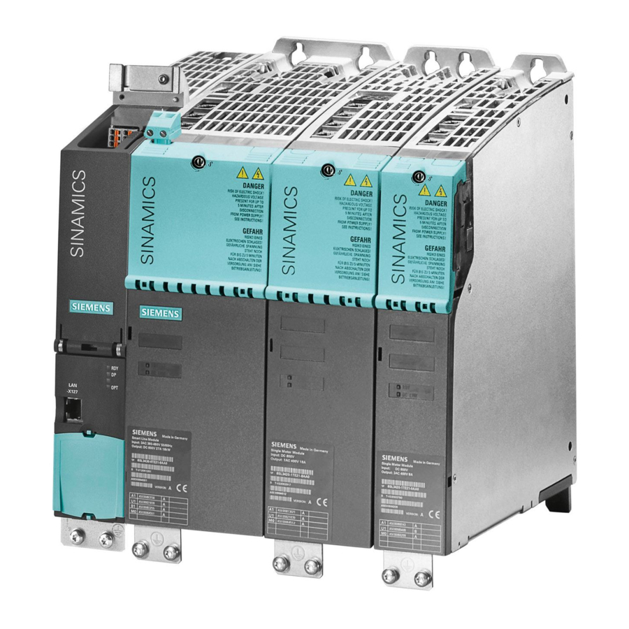
System overview 1.5 SINAMICS S120 Components SINAMICS S120 Components This overview features the SINAMICS S120 components that are primarily used for multi- axis drive tasks. Figure 1-5 SINAMICS S120 component overview Equipment Manual for Booksize Power Units Equipment Manual, (GH2), 03/2006 Edition, 6SL3097-2AC00-0BP3... - Page 24 • Additional system components that enhance functionality and offer different interfaces for encoders and process signals. The SINAMICS S120 components were developed for installation in cabinets. They have the following features and characteristics: • Easy to handle, simple installation and wiring •...
-
Page 25: Power Sections
System overview 1.6 Power Sections Power Sections Line modules Convert the three-phase supply into a DC voltage for the DC link. • Smart line modules The smart line modules generate a non-stabilized DC link voltage and are capable of regenerative feedback. •... -
Page 26: System Data
1.7 System Data System Data Technical Specifications Unless explicitly specified otherwise, the following technical specifications are valid for components of the SINAMICS S120 booksize drive system. Electrical specifications Line connection voltage 3-ph. 380 V to 480 V AC ±10 % (-15 % <... - Page 27 System overview 1.7 System Data Information and instructions for long-term storage in the transport packaging, transport in the transport packaging and operation: Environmental class Long-term storage in the transport packaging • Class 1C2 acc. to EN 60 721-3-1 Class 2C2 acc. to EN 60 721-3-2 Transport in transport packaging •...
-
Page 28: Standards
System overview 1.8 Standards Standards Table 1-1 Essentially, standards relevant to the particular application Standards Title EN 292-1 Safety of machines; general design guidelines; Part 1: General terminology, methodology: EN 292-2 Safety of machines; general design guidelines; Part 2: Technical principles and specifications EN 563 Safety of machines;... - Page 29 System overview 1.8 Standards Standards Title EN 61800-2 Variable-speed electric drives; Part 2: General requirements - definitions for dimensioning low-voltage AC drive systems with an adjustable frequency EN 61800-3 Variable-speed electric drives; Part 3: EMC requirements including special test procedures EN 61800-5-X Electrical power drive systems with an adjustable speed;...
-
Page 31: Line Connection Booksize
Caution The following can occur if line filters are used that have not been approved for SINAMICS by SIEMENS: - The Line Modules may become damaged/faulty. - Line reactions can occur that can damage or interfere with other loads powered from the same network. -
Page 32: Overview: Line Filters
EN 55011 or Category C2 acc. to EN 61800-3. Optional line filter series that are coordinated with the power range are also available with the SINAMICS S120 converter system. These line filters differ with regard to the frequency range in which they reduce the conducted emissions. -
Page 33: Basic Line Filter For Active Line Modules
Line Connection Booksize 2.3 Basic Line Filter for Active Line Modules Basic Line Filter for Active Line Modules 2.3.1 Description The Basic Line Filters for Active Line Modules have the task of damping the conducted noise that is emitted in the frequency range according to that specified in the EMC legislation. The machinery construction OEM must carry-out a certification for the machines that he wishes to market according to the EC Directive EMC. -
Page 34: Safety Information
Line Connection Booksize 2.3 Basic Line Filter for Active Line Modules 2.3.2 Safety information Caution Line filters are only suitable for direct connection to TN line supplies. Danger The 100 mm clearances above and below the components must be observed. This measure prevents thermal overloading of the filter. -
Page 35: Interface Description
Line Connection Booksize 2.3 Basic Line Filter for Active Line Modules 2.3.3 Interface Description 2.3.3.1 Overview Figure 2-2 Basic Line Filter for Active Line Modules (example: 36 kW) Equipment Manual for Booksize Power Units Equipment Manual, (GH2), 03/2006 Edition, 6SL3097-2AC00-0BP3... -
Page 36: Line/Load Connection
Line Connection Booksize 2.3 Basic Line Filter for Active Line Modules 2.3.3.2 Line/load connection Table 2-2 Type of connection Terminals Designations Line supply connection (line supply) L1, L2, L3, PE Load connection (load) L1´, L2´, L3´, PE Basic Line Filter for Active Line Modules 16 kW Screw terminal: 10 mm 3-pin/1.5 Nm (see Screw Terminals) -
Page 37: Dimension Drawing
Line Connection Booksize 2.3 Basic Line Filter for Active Line Modules 2.3.4 Dimension Drawing Figure 2-3 Dimension drawing: Basic Line Filter for Active Line Modules (16 kW to 55 kW) Table 2-3 Dimensions: Basic Line Filter for Active Line Modules Basic Line Order number B [mm]... -
Page 38: Wideband Line Filter For Active Line Modules
Line Connection Booksize 2.4 Wideband Line Filter for Active Line Modules Wideband Line Filter for Active Line Modules 2.4.1 Description The damping characteristics of Wideband Line Filters for Active Line Modules not only conform with the requirements of EMC standards for the frequency range of 150 kHz to 30 MHz but also include low frequencies as of 2 kHz. - Page 39 Line Connection Booksize 2.4 Wideband Line Filter for Active Line Modules Caution The line filters listed conduct a high leakage current via the PE conductor. Because of the high leakage current of the line filters, a permanent PE connection of the line filter or switching cabinet is required.
-
Page 40: Interface Description
Line Connection Booksize 2.4 Wideband Line Filter for Active Line Modules 2.4.3 Interface description Figure 2-4 Wideband Line Filters for Active Line Module (example: 16kW) Equipment Manual for Booksize Power Units 2-10 Equipment Manual, (GH2), 03/2006 Edition, 6SL3097-2AC00-0BP3... -
Page 41: Line/Load Connection
Line Connection Booksize 2.4 Wideband Line Filter for Active Line Modules 2.4.3.1 Line/load connection Wideband Line Filters for Active Line Modules are designed for a voltage range from 3-ph. 380 V AC -10% (-15% <1 min) up to 3-ph. 480 V AC +10% at 47 Hz to 63 Hz. Table 2-5 Type of connection Terminals... -
Page 42: Dimension Drawing
Line Connection Booksize 2.4 Wideband Line Filter for Active Line Modules 2.4.4 Dimension Drawing Figure 2-5 Dimension drawing: Wideband Line Filter for Active Line Modules Equipment Manual for Booksize Power Units 2-12 Equipment Manual, (GH2), 03/2006 Edition, 6SL3097-2AC00-0BP3... -
Page 43: Technical Specifications
Line Connection Booksize 2.4 Wideband Line Filter for Active Line Modules Table 2-6 Dimensions: Wideband Line Filter For Active Line Order number a [mm] b [mm] c [mm] [mm] [mm] Modules 6SL3000- (inches) (inches) (inches) (inches) (inches) 16 kW 0BE-21-6AAx 130 (5.12) 100 (3.94) 15 (0.59) -
Page 44: Line Filters For Smart Line Modules
Line Connection Booksize 2.5 Line filters for Smart Line Modules Line filters for Smart Line Modules 2.5.1 Description Line filters for Smart Line Modules, in conjunction with the associated line reactors, limit the cable-conducted noise emission to a level in conformance with E55011, Class A1. General conditions regarding line filters for Smart Line Modules •... - Page 45 Line Connection Booksize 2.5 Line filters for Smart Line Modules Caution The line filters listed conduct a high leakage current via the PE conductor. Because of the high leakage current of the line filters, a permanent PE connection of the line filter or switching cabinet is required.
-
Page 46: Interface Description
Line Connection Booksize 2.5 Line filters for Smart Line Modules 2.5.3 Interface description 2.5.3.1 Overview Figure 2-6 Line filters for Smart Line Modules (example: 36 kW) Equipment Manual for Booksize Power Units 2-16 Equipment Manual, (GH2), 03/2006 Edition, 6SL3097-2AC00-0BP3... -
Page 47: Line/Load Connection
Line Connection Booksize 2.5 Line filters for Smart Line Modules 2.5.3.2 Line/load connection Line filters for Smart Line Modules are rated for a voltage range from 3-ph. 380 V AC -10% (-15% <1 min) up to 3-ph. 480 V AC +10% at 47 Hz to 63 Hz. Table 2-8 Type of connection Terminals... -
Page 48: Dimension Drawings
Line Connection Booksize 2.5 Line filters for Smart Line Modules 2.5.4 Dimension Drawings Figure 2-7 Dimension drawing: line filters for Smart Line Modules (5 and 10 kW) Table 2-9 Line filters for Smart Line Modules Line filters for Smart Line Modules Order No. -
Page 49: Technical Specifications
Line Connection Booksize 2.5 Line filters for Smart Line Modules Figure 2-8 Dimension drawing: line filter for Smart Line Module (16 kW and 36 kW) Table 2-10 Dimensions: line filter for Smart Line Module Line filters for Order No. B [mm] b [mm] a [mm] H [mm]... -
Page 50: Line Reactors For Active Line Modules
150 mm. Caution Only the line reactors described in this Equipment Manual must be used. When using line reactors that have not been released by SIEMENS for SINAMICS S120, the following can occur: - can damage/destroy Line Modules. -
Page 51: Connection Description
Line Connection Booksize 2.6 Line reactors for Active Line Modules 2.6.3 Connection description The line reactor is rated for a voltage range from 3-ph. 380 V AC -10% to 3-ph. 480 V AC +10% at 47 Hz to 63 Hz. Figure 2-9 Line reactor (example: 16 kW) 2.6.3.1... -
Page 52: Dimension Drawing
Line Connection Booksize 2.6 Line reactors for Active Line Modules 2.6.4 Dimension drawing Figure 2-10 Dimension drawing: line reactor for Active Line Modules (up to 55 kW) Table 2-13 Dimensions of the line reactor for Active Line Modules Order number L [mm] W [mm] h [mm]... -
Page 53: Technical Specifications
Line Connection Booksize 2.6 Line reactors for Active Line Modules Table 2-14 Dimensions of the line reactor for Active Line Modules Order L [mm] W [mm] h1 [mm] h2 [mm] H [mm] b [mm] [mm] [mm] [mm] number (inches) (inches) (inches) (inches) (inches) -
Page 54: Line Reactors For Smart Line Modules
150 mm. Caution Only the line reactors described in this Equipment Manual must be used. When using line reactors that have not been released by SIEMENS for SINAMICS S120, the following can occur: - can damage/destroy Line Modules. -
Page 55: Connection Description
Line Connection Booksize 2.7 Line reactors for Smart Line Modules 2.7.3 Connection description Figure 2-12 Line reactors for Smart Line Modules (example: 36 kW) 2.7.3.1 Line/load connection Table 2-16 Connection methods for line reactor Terminals Designations Power supply 1U1, 1V1, 1W1, PE Load connection 1U2, 1V2, 1W2 Line reactors for Smart Line Modules... -
Page 56: Dimension Drawings
Line Connection Booksize 2.7 Line reactors for Smart Line Modules 2.7.4 Dimension Drawings Figure 2-13 Dimension drawing: line reactor for Smart Line Modules (5 and 10 KW) Table 2-17 Dimensions of the line filter for Smart Line Modules Order number W [mm] w [mm] H [mm]... - Page 57 Line Connection Booksize 2.7 Line reactors for Smart Line Modules Figure 2-14 Dimension drawing of line reactor for the Smart Line Module 16 kW Equipment Manual for Booksize Power Units 2-27 Equipment Manual, (GH2), 03/2006 Edition, 6SL3097-2AC00-0BP3...
- Page 58 Line Connection Booksize 2.7 Line reactors for Smart Line Modules Figure 2-15 Dimension drawing of the line reactor for the Smart Line Module 36 kW Equipment Manual for Booksize Power Units 2-28 Equipment Manual, (GH2), 03/2006 Edition, 6SL3097-2AC00-0BP3...
-
Page 59: Technical Specifications
Line Connection Booksize 2.7 Line reactors for Smart Line Modules Table 2-18 Line reactor for the Smart Line Modules 16 kW and 36 kW Order number 6SL3000- 16 kW 0CE-21-6AA0 36 KW 0CE-23-6AA0 2.7.5 Technical specifications Table 2-19 Technical specifications of line reactors for the Smart Line Module 6SL3000 0CE15-0AA0 0CE21-0AA0... -
Page 60: Line Connection Variations
Line Connection Booksize 2.8 Line connection variations Line connection variations 2.8.1 Methods of line connection A distinction is made between: • Direct operation of the line connection components on the supply • Operation of the Line Connection Components via an Autotransformer •... -
Page 61: Operation Of The Line Connection Components On The Supply Network
Line Connection Booksize 2.8 Line connection variations 2.8.2 Operation of the line connection components on the supply network The SINAMICS S booksize drive system is rated for direct operation on TN, TT, and IT line supply systems with a rated voltage of 3-ph. 380 V to 3-ph. 480 V AC. Operation with a line filter is only permitted for a TN line supply. - Page 62 Line Connection Booksize 2.8 Line connection variations Applications: • The motor insulation must be protected from excessive voltages. • The active line module must provide a stabilized DC link voltage. It can be in the range 380 V to 415 V. Figure 2-18 Autotransformer Equipment Manual for Booksize Power Units...
-
Page 63: Operation Of The Line Connection Components Via An Isolating Transformer
Line Connection Booksize 2.8 Line connection variations 2.8.4 Operation of the line connection components via an isolating transformer The isolating transformer converts the network configuration of the system (e.g. IT/TT system) to a TN system. Additional voltage adaptation to the permissible voltage tolerance range is possible. - Page 64 Line Connection Booksize 2.8 Line connection variations Figure 2-19 Isolating transformer Equipment Manual for Booksize Power Units 2-34 Equipment Manual, (GH2), 03/2006 Edition, 6SL3097-2AC00-0BP3...
-
Page 65: Line Connection Via A Ground-Fault Circuit Interrupter
Line Connection Booksize 2.8 Line connection variations 2.8.5 Line connection via a ground-fault circuit interrupter In addition to protective measures against direct and indirect contact, selectively tripping AC/DC-sensitive residual-current circuit-breakers (Type B) can be used. Danger Residual-current circuit-breakers alone are not permissible to provide protection against direct and indirect contact. - Page 66 35ms delay time between closing and opening individual main contacts. Recommendation SIEMENS selectively tripping AC/DC-sensitive residual-current circuit-breakers to EN 61800-5-1, type 5SZ (e.g. 5SZ6 468–0KG00 or 5SZ6468–0KG30 with auxiliary disconnector (1NC/1NO) for rated current 63 A, rated fault current 0.3 A) (also refer to Catalog CA01).
-
Page 67: Line Modules Booksize
Line Modules Booksize Introduction Line Modules generate a DC voltage that is used to power the Motor Modules from the connected supply voltage. The Active Line Modules and the Smart Line Modules 16 kW and 36 kW have DRIVE-CLiQ interfaces for communications with the Control Unit. The Smart Line Modules 5 kW and 10 kW must be connected with the Control Unit via terminals. - Page 68 Line Modules Booksize 3.1 Introduction Characteristics of the Active Line Modules • Regulated DC link voltage • Regenerative feedback capability • Sinusoidal line currents • Electronic type plate • DRIVE-CLiQ interface for communication with the Control Unit and/or other components in the drive line-up.
-
Page 69: Active Line Modules With Internal Air Cooling
Line Modules Booksize 3.2 Active Line Modules with Internal Air Cooling Active Line Modules with Internal Air Cooling 3.2.1 Description Active Line Modules generate a constant, regulated DC voltage from the three-phase line supply voltage that supplies the connected Motor Modules with power. This ensures that they are not influenced by network fluctuations. - Page 70 For the 80 kW and 120 kW Active Line Modules, a ventilation clearance of 50 mm must be observed in front of the fan. Caution It is only permissible to establish connections to the DC link using the adapters that Siemens has recommended (DC link adapter and DC link infeed adapter). Caution The tightening torque of the DC link busbar screws (1.8 Nm, tolerance: +30%) must be...
- Page 71 350 m in Active mode and 560 m in Smart mode. Caution Only cables from Siemens must be used for DRIVE-CLiQ connections. Caution The ratio between the system fault level and the rated power of the Line Module must be ≥...
-
Page 72: Interface Description
Line Modules Booksize 3.2 Active Line Modules with Internal Air Cooling 3.2.3 Interface description 3.2.3.1 Overview Figure 3-2 Active line module with internal air cooling (example: 16 kW) Equipment Manual for Booksize Power Units Equipment Manual, (GH2), 03/2006 Edition, 6SL3097-2AC00-0BP3... -
Page 73: Connection Example
Line Modules Booksize 3.2 Active Line Modules with Internal Air Cooling 3.2.3.2 Connection example Ext. 24 V X200 X201 X202 +Temp -Temp Active line EP +24 V module EP M 24 V DC 3)4) READY DC LINK Figure 3-3 Example connection of Active Line Module Equipment Manual for Booksize Power Units Equipment Manual, (GH2), 03/2006 Edition, 6SL3097-2AC00-0BP3... -
Page 74: X1 Line Connection
Line Modules Booksize 3.2 Active Line Modules with Internal Air Cooling 3.2.3.3 X1 line connection Table 3-1 Terminal block X1 Active Line Module 16 kW Terminal Technical data Max. connectable cross-section: 10 mm Type: Screw terminal 6 (see Connection Methods) Tightening torque: 1.5 - 1.8 Nm PE connection Threaded hole M5/3 Nm... -
Page 75: X200-X202 Drive-Cliq Interfaces
Line Modules Booksize 3.2 Active Line Modules with Internal Air Cooling 3.2.3.4 X200-X202 DRIVE-CLiQ interfaces Table 3-3 DRIVE-CLiQ interface X200-X202 Signal name Technical specifications Transmit data + Transmit data - Receive data + Reserved, do not use Reserved, do not use Receive data - Reserved, do not use Reserved, do not use... -
Page 76: X24 24 V Terminal Adapter
Line Modules Booksize 3.2 Active Line Modules with Internal Air Cooling 3.2.3.6 X24 24 V terminal adapter Table 3-5 Terminal block X24 Terminal Name Technical specifications 24 V supply 24 V DC supply voltage M (GND) Ground Electronic ground The 24 V terminal adapter is supplied as standard Max. -
Page 77: Dimension Drawing
Line Modules Booksize 3.2 Active Line Modules with Internal Air Cooling Cause and rectification of faults The following reference contains information about the cause and rectification of faults: Reference: /IH1/ SINAMICS S120, Commissioning Manual. 3.2.4 Dimension drawing Figure 3-4 Dimension drawing of Active Line Module with internal air cooling (16 kW) - Page 78 Line Modules Booksize 3.2 Active Line Modules with Internal Air Cooling Table 3-7 Dimensions of Active Line Module with internal air cooling Active Line Module Order number W [mm] (inches) w [mm] (inches) h [mm] (inches) type 16 kW 6SL3130-7TE21-6AAx 100 (3.94) 50 (1.97) 18 (0.71) Note...
- Page 79 Line Modules Booksize 3.2 Active Line Modules with Internal Air Cooling Table 3-8 Dimensions of Active Line Module with internal air cooling Active Line Module Order number W [mm] (inches) w [mm] (inches) h [mm] (inches) Type 36 kW 6SL3130-7TE23-6AAx 150 (5.91) 100 (3.94) 105 (4.13) 55 kW...
-
Page 80: Installation
Line Modules Booksize 3.2 Active Line Modules with Internal Air Cooling 3.2.5 Installation Installing the fan on Active Line Modules (80 kW and 120 kW) Figure 3-7 Installing the fan for 300 mm modules 1) Secure with M6/6 Nm screws 2) Connect the power supply for the fan Note The fans are power-up and power-down as a function of the heatsink temperature. - Page 81 Line Modules Booksize 3.2 Active Line Modules with Internal Air Cooling Remove the holder for securing the Control Unit. If an additional component is to be flush-mounted to the left of the component, the holders for securing the Control Unit must be removed. Use suitable tools to lift the latching device Remove the holder.
-
Page 82: Electrical Connection
Line Modules Booksize 3.2 Active Line Modules with Internal Air Cooling 3.2.6 Electrical connection Figure 3-8 Busbar connections for booksize components Notice The 24 V connector may only be withdrawn vertically to the front panel (i.e. not at an angle)! Equipment Manual for Booksize Power Units 3-16 Equipment Manual, (GH2), 03/2006 Edition, 6SL3097-2AC00-0BP3... -
Page 83: Technical Specifications
Line Modules Booksize 3.2 Active Line Modules with Internal Air Cooling 3.2.7 Technical specifications Table 3-10 Technical specifications of Active Line Modules Internal air cooling 6SL3130– 7TE21– 7TE23– 7TE25– 7TE28– 7TE31– 6AAx 6AAx 5AAx 0AAx 2AAx Rated power Infeed: Rated power (S1) kW (Pn) Infeed power (S6-40%) kW (Ps6) - Page 84 Line Modules Booksize 3.2 Active Line Modules with Internal Air Cooling Internal air cooling 6SL3130– 7TE21– 7TE23– 7TE25– 7TE28– 7TE31– 6AAx 6AAx 5AAx 0AAx 2AAx Rated power Rated voltage for rated data, 3-ph. 380 V AC Weight 1 The specified values apply to 380 V 2 For an overview, see the power loss tables in Cabinet Design.
- Page 85 Line Modules Booksize 3.2 Active Line Modules with Internal Air Cooling Derating as a function of the ambient temperature Figure 3-10 Derating as a function of the ambient temperature Derating as a function of the installation altitude Figure 3-11 Derating as a function of the installation altitude Equipment Manual for Booksize Power Units 3-19 Equipment Manual, (GH2), 03/2006 Edition, 6SL3097-2AC00-0BP3...
-
Page 86: Active Line Modules With External Air Cooling
Line Modules Booksize 3.3 Active Line Modules with External Air Cooling Active Line Modules with External Air Cooling 3.3.1 Description The Motor Modules are connected to the power supply network via the Active Line Modules with external air cooling, which provide the Motor Modules with a constant DC link voltage. This ensures that they are not influenced by network fluctuations. - Page 87 The 80 mm clearances above and below the components must be observed. Caution It is only permissible to establish connections to the DC link using the adapters that Siemens has recommended (DC link adapter and DC link infeed adapter). Caution The tightening torque of the DC link busbar screws (1.8 Nm, tolerance: +30%) must be...
- Page 88 The total length of all the power cables (motor supply cables and DC link cables) must not exceed 350 m in active mode. Caution Only cables from Siemens must be used for DRIVE-CLiQ connections. Notice The external air cooling can cause the fans and the heat sink to become heavily contaminated, which may trigger the temperature monitor in the power unit.
-
Page 89: Interface Description
Line Modules Booksize 3.3 Active Line Modules with External Air Cooling 3.3.3 Interface description 3.3.3.1 Overview Figure 3-12 Active line module with external air cooling (example: 16 kW) Equipment Manual for Booksize Power Units 3-23 Equipment Manual, (GH2), 03/2006 Edition, 6SL3097-2AC00-0BP3... -
Page 90: Connection Example
Line Modules Booksize 3.3 Active Line Modules with External Air Cooling 3.3.3.2 Connection example Ext. 24 V X200 X201 X202 +Temp -Temp Active line EP +24 V module EP M 24 V DC 3)4) READY DC LINK Figure 3-13 Example connection of Active Line Module Equipment Manual for Booksize Power Units 3-24 Equipment Manual, (GH2), 03/2006 Edition, 6SL3097-2AC00-0BP3... -
Page 91: Line Connection
Line Modules Booksize 3.3 Active Line Modules with External Air Cooling 3.3.3.3 Line connection Table 3-11 Terminal block X1 Active Line Module 16 kW Terminal Technical specifications Supply voltage: 3AC 480 V +10% (-15% < 1 min) at 47 Hz to 63 Hz Max. -
Page 92: X200-X202 Drive-Cliq Interfaces
Line Modules Booksize 3.3 Active Line Modules with External Air Cooling 3.3.3.4 X200-X202 DRIVE-CLiQ interfaces Table 3-13 DRIVE-CLiQ interface X200-X202 Signal name Technical specifications Transmit data + Transmit data - Receive data + Reserved, do not use Reserved, do not use Receive data - Reserved, do not use Reserved, do not use... -
Page 93: X24 24 V Terminal Adapter
Line Modules Booksize 3.3 Active Line Modules with External Air Cooling 3.3.3.6 X24 24 V terminal adapter Table 3-15 Terminal block X24 Terminal Name Technical specifications 24 V supply 24 V DC supply voltage M (GND) Ground Electronic ground The 24 V terminal adapter is supplied as standard Max. -
Page 94: Dimension Drawings
Line Modules Booksize 3.3 Active Line Modules with External Air Cooling Cause and rectification of faults The following reference contains information about the cause and rectification of faults: Reference: /IH1/ SINAMICS S120, Commissioning Manual. 3.3.4 Dimension Drawings Figure 3-14 Dimension drawing of Active Line Module with external air cooling (16 kW) - Page 95 Line Modules Booksize 3.3 Active Line Modules with External Air Cooling Table 3-17 Dimensions of Active Line Module with external air cooling (16 kW) Line Module type Order number W [mm] w [mm] (inches) c [mm] (inches) h [mm] (inches) (inches) 16 kW 6SL3130-7TE21-...
- Page 96 Line Modules Booksize 3.3 Active Line Modules with External Air Cooling Table 3-18 Dimensions of Active Line Modules with external air cooling (36 kW, 55 kW, 80 kW, and 120 kW) Line Module type Order number W [mm] (inches) w [mm] (inches) h [mm] (inches) c [mm] (inches) 36 kW...
-
Page 97: Installation
3.3 Active Line Modules with External Air Cooling 3.3.5 Installation Figure 3-16 Example: installing the power unit with external air cooling Help with the mechanical cabinet design is available from: Siemens AG A&D SE WKC CoC CabinetCooling P.O. Box 1124 D-09070 Chemnitz, Germany E-mail: mailto:cc.cabinetcooling@siemens.com... - Page 98 Line Modules Booksize 3.3 Active Line Modules with External Air Cooling Figure 3-17 Installation openings for the power unit with external air cooling, 50 mm to 200 mm Equipment Manual for Booksize Power Units 3-32 Equipment Manual, (GH2), 03/2006 Edition, 6SL3097-2AC00-0BP3...
- Page 99 Line Modules Booksize 3.3 Active Line Modules with External Air Cooling Figure 3-18 Installation openings for the power unit with external air cooling, 300 mm Table 3-19 Dimensions of the installation openings for the power unit with external air cooling Component width W [mm] (inches) w1 [mm] (inches)
- Page 100 Line Modules Booksize 3.3 Active Line Modules with External Air Cooling Figure 3-19 Example: mounting plate with a drive line-up When installing the module, you must ensure that the module seal is tight all round. The cross-pieces must be sufficiently stable. If required, we recommend that you reinforce the cross-pieces for the recesses.
- Page 101 Line Modules Booksize 3.3 Active Line Modules with External Air Cooling Figure 3-20 Example 1: installation in cabinet with mounting plate Equipment Manual for Booksize Power Units 3-35 Equipment Manual, (GH2), 03/2006 Edition, 6SL3097-2AC00-0BP3...
- Page 102 Line Modules Booksize 3.3 Active Line Modules with External Air Cooling Figure 3-21 Example 2: installation in cabinet with mounting plate We recommend that you attach a cover and filtered fan to the cabinet. The filtered fan must be fitted in such a way that the cooling air required by the drive line-up is not restricted.
- Page 103 Line Modules Booksize 3.3 Active Line Modules with External Air Cooling Remove the holder for securing the Control Unit If an additional component is to be flush-mounted to the left of the component, the holders for securing the Control Unit must be removed. Use suitable tools to lift the latching Remove the holder.
-
Page 104: Electrical Connection
Line Modules Booksize 3.3 Active Line Modules with External Air Cooling 3.3.6 Electrical connection Figure 3-22 Busbar connections for booksize components Notice The 24 V connector may only be withdrawn vertically to the front panel (i.e. not at an angle)! Equipment Manual for Booksize Power Units 3-38 Equipment Manual, (GH2), 03/2006 Edition, 6SL3097-2AC00-0BP3... -
Page 105: Technical Specifications
Line Modules Booksize 3.3 Active Line Modules with External Air Cooling 3.3.7 Technical specifications Table 3-20 Technical specifications for Active Line Modules with external air cooling Internal air cooling 6SL3131– 7TE21– 7TE23– 7TE25– 7TE28– 7TE31- 6AAx 6AAx 5AAx 0AAx 2AAx Rated power Infeed: Rated power (S1) - Page 106 Line Modules Booksize 3.3 Active Line Modules with External Air Cooling Internal air cooling 6SL3131– 7TE21– 7TE23– 7TE25– 7TE28– 7TE31- 6AAx 6AAx 5AAx 0AAx 2AAx Rated power Cooling air requirement Rated voltage for rated data, 3-ph. 380 V AC Weight 8.78 13.77 18.5...
- Page 107 Line Modules Booksize 3.3 Active Line Modules with External Air Cooling Derating as a function of the ambient temperature Figure 3-24 Derating as a function of the ambient temperature Derating as a function of the installation altitude Figure 3-25 Derating as a function of the installation altitude Equipment Manual for Booksize Power Units 3-41 Equipment Manual, (GH2), 03/2006 Edition, 6SL3097-2AC00-0BP3...
-
Page 108: Smart Line Modules (5 Kw And 10 Kw) With Internal Air Cooling
Line Modules Booksize 3.4 Smart Line Modules (5 kW and 10 kW) with internal air cooling Smart Line Modules (5 kW and 10 kW) with internal air cooling 3.4.1 Description The Smart Line Module (SLM) is an unregulated line infeed/feedback unit. The SLM supplies the Motor Module(s) with an unregulated DC voltage at the DC output. - Page 109 The 80 mm clearances above and below the components must be observed. Caution It is only permissible to establish connections to the DC link using the adapters that Siemens has recommended (DC link adapter and DC link infeed adapter). Caution The tightening torque of the DC link busbar screws (1.8 Nm, tolerance: +30%) must be...
- Page 110 Line Modules Booksize 3.4 Smart Line Modules (5 kW and 10 kW) with internal air cooling Caution The total length of the power cables (motor supply cables and DC link cables) must not exceed 350 m. Notice Operation without the line reactor is not permissible. Caution The ratio of line short-circuit power to rated power must be ≧...
-
Page 111: Interface Description
Line Modules Booksize 3.4 Smart Line Modules (5 kW and 10 kW) with internal air cooling 3.4.3 Interface Description 3.4.3.1 Overview Figure 3-26 Smart line module with internal air cooling (example 5 kW) Equipment Manual for Booksize Power Units 3-45 Equipment Manual, (GH2), 03/2006 Edition, 6SL3097-2AC00-0BP3... -
Page 112: Connection Example
Line Modules Booksize 3.4 Smart Line Modules (5 kW and 10 kW) with internal air cooling 3.4.3.2 Connection example Figure 3-27 Example connection of Smart Line Module Equipment Manual for Booksize Power Units 3-46 Equipment Manual, (GH2), 03/2006 Edition, 6SL3097-2AC00-0BP3... -
Page 113: X1 Line Connection
Line Modules Booksize 3.4 Smart Line Modules (5 kW and 10 kW) with internal air cooling 3.4.3.3 X1 line connection Table 3-21 Terminal block X1 of Smart Line Module (5 kW and 10 kW) Terminal Technical data Max. connection voltage: 3-ph. -
Page 114: X22 Terminals: Smart Line Module
Line Modules Booksize 3.4 Smart Line Modules (5 kW and 10 kW) with internal air cooling Note For operation, 24 V DC must be connected to terminal 3 and ground to terminal 4. When removed, pulse inhibit is activated, feedback is deactivated and the bypass relay drops out. If the Line Module is not disconnected from the network when the EP terminal is deactivated (e.g. -
Page 115: Meaning Of The Leds On The Smart Line Module
The warning information on the components must be carefully observed! Cause and rectification of faults The following reference contains information about the cause and rectification of faults: Reference: /IH1/ SINAMICS S120 Commissioning Manual Equipment Manual for Booksize Power Units 3-49... -
Page 116: Dimension Drawing
Line Modules Booksize 3.4 Smart Line Modules (5 kW and 10 kW) with internal air cooling 3.4.4 Dimension Drawing Figure 3-28 Dimension drawing of the 5 kW and 10 kW Smart Line Modules with internal air cooling Table 3-26 Dimensions of 5 kW and 10 kW Smart Line Modules with internal air cooling Line Module type Order number W [mm] (inches) -
Page 117: Installation
Line Modules Booksize 3.4 Smart Line Modules (5 kW and 10 kW) with internal air cooling 3.4.5 Installation Remove the holder for securing the Control Unit Various expansion version make it necessary to remove the plastic retaining element: • If the component to be mounted comes into contact with the lefthand cabinet panel •... -
Page 118: Electrical Connection
Line Modules Booksize 3.4 Smart Line Modules (5 kW and 10 kW) with internal air cooling 3.4.6 Electrical Connection Figure 3-29 Busbar connections for booksize components Equipment Manual for Booksize Power Units 3-52 Equipment Manual, (GH2), 03/2006 Edition, 6SL3097-2AC00-0BP3... -
Page 119: Technical Specifications
Line Modules Booksize 3.4 Smart Line Modules (5 kW and 10 kW) with internal air cooling 3.4.7 Technical Specifications Table 3-27 Technical specifications for Smart Line Modules in booksize format with internal air cooling Internal air cooling 6SL3130– 6AE15–0AAx 6AE21–0AAx Rated power Supply: Rated power (S1) - Page 120 Line Modules Booksize 3.4 Smart Line Modules (5 kW and 10 kW) with internal air cooling Internal air cooling 6SL3130– 6AE15–0AAx 6AE21–0AAx Rated power Rated voltage for rated data 3 AC 380 V Weight 4.68 4.78 1 The specified values apply to 380 V 2 For an overview, see the power loss tables in Cabinet Design.
- Page 121 Line Modules Booksize 3.4 Smart Line Modules (5 kW and 10 kW) with internal air cooling Derating as a function of the ambient temperature Permissible output power [°C] Ambient temperature Figure 3-31 Derating as a function of the ambient temperature Derating as a function of the installation altitude Permissible output power 1000...
-
Page 122: Smart Line Modules (16 Kw And 36 Kw) With Internal Air Cooling
Line Modules Booksize 3.5 Smart Line Modules (16 kW and 36 kW) with internal air cooling Smart Line Modules (16 kW and 36 kW) with internal air cooling 3.5.1 Description The Smart Line Module is an unregulated infeed/regenerative feedback unit. The Smart Line Module supplies the Motor Module(s) with an unregulated DC voltage at the DC output. - Page 123 The 80 mm clearances above and below the components must be observed. Caution It is only permissible to establish connections to the DC link using the adapters that Siemens has recommended (DC link adapter and DC link infeed adapter). Caution The tightening torque of the DC link busbar screws (1.8 Nm, tolerance: +30%) must be...
- Page 124 Line Modules Booksize 3.5 Smart Line Modules (16 kW and 36 kW) with internal air cooling Caution The total length of the power cables (motor supply cables and DC link cables) must not exceed 350 m. Notice Operation without the line reactor is not permissible. Caution The ratio of line short-circuit power to rated power must be ≧...
-
Page 125: Interface Description
Line Modules Booksize 3.5 Smart Line Modules (16 kW and 36 kW) with internal air cooling 3.5.3 Interface description 3.5.3.1 Overview Figure 3-33 Smart Line Module with internal air cooling (example 16 kW) Equipment Manual for Booksize Power Units 3-59 Equipment Manual, (GH2), 03/2006 Edition, 6SL3097-2AC00-0BP3... - Page 126 Line Modules Booksize 3.5 Smart Line Modules (16 kW and 36 kW) with internal air cooling Figure 3-34 Smart Line Module with internal air cooling (example 36 kW) Equipment Manual for Booksize Power Units 3-60 Equipment Manual, (GH2), 03/2006 Edition, 6SL3097-2AC00-0BP3...
-
Page 127: Connection Example
Line Modules Booksize 3.5 Smart Line Modules (16 kW and 36 kW) with internal air cooling 3.5.3.2 Connection example Figure 3-35 Connection example: Smart Line Module (16 kW and 36 kW) Equipment Manual for Booksize Power Units 3-61 Equipment Manual, (GH2), 03/2006 Edition, 6SL3097-2AC00-0BP3... -
Page 128: X1 Line Connection
Line Modules Booksize 3.5 Smart Line Modules (16 kW and 36 kW) with internal air cooling 3.5.3.3 X1 line connection Table 3-28 Terminal block X1 Smart Line Module 16 kW Terminal Technical specifications Supply voltage: 3-ph. 480 V AC +10% (-15% < 1 min) at 47 Hz to 63 Hz Max. -
Page 129: X200-X202 Drive-Cliq Interfaces
Line Modules Booksize 3.5 Smart Line Modules (16 kW and 36 kW) with internal air cooling 3.5.3.4 X200-X202 DRIVE-CLiQ interfaces Table 3-30 DRIVE-CLiQ interface X200-X202 Signal name Technical specifications Transmit data + Transmit data - Receive data + Reserved, do not use Reserved, do not use Receive data - Reserved, do not use... -
Page 130: X24 24 V Terminal Adapter
Line Modules Booksize 3.5 Smart Line Modules (16 kW and 36 kW) with internal air cooling 3.5.3.6 X24 24 V terminal adapter Table 3-32 Terminal block X24 Terminal Name Technical specifications 24 V supply 24 V DC supply voltage M (GND) Ground Electronic ground The 24 V terminal adapter is supplied as standard... -
Page 131: Dimension Drawings
3.5 Smart Line Modules (16 kW and 36 kW) with internal air cooling Cause and rectification of faults The following reference contains information about the cause and rectification of faults: Reference: /IH1/ SINAMICS S120, Commissioning Manual. 3.5.4 Dimension Drawings Figure 3-36... - Page 132 Line Modules Booksize 3.5 Smart Line Modules (16 kW and 36 kW) with internal air cooling Table 3-34 Dimensions of Smart Line Module with internal air cooling Smart Line Module Order number W [mm] (inches) w [mm] (inches) h [mm] (inches) Type 16 kW 6SL3130-6TE21-6ABx...
-
Page 133: Installation
Line Modules Booksize 3.5 Smart Line Modules (16 kW and 36 kW) with internal air cooling Table 3-35 Dimensions of Smart Line Module with internal air cooling Smart Line Module Order number W [mm] (inches) w [mm] (inches) h [mm] (inches) Type 36 kW 6SL3130-6TE23-6ABx... -
Page 134: Electrical Connection
Line Modules Booksize 3.5 Smart Line Modules (16 kW and 36 kW) with internal air cooling 3.5.6 Electrical Connection Figure 3-38 Busbar connections for booksize components Equipment Manual for Booksize Power Units 3-68 Equipment Manual, (GH2), 03/2006 Edition, 6SL3097-2AC00-0BP3... -
Page 135: Technical Specifications
Line Modules Booksize 3.5 Smart Line Modules (16 kW and 36 kW) with internal air cooling 3.5.7 Technical specifications Table 3-36 Technical specifications for Smart Line Modules in booksize format with internal air cooling Internal air cooling 6SL3130– 6TE21-6ABx 6TE23-6ABx Rated power Supply: Rated power (S1) - Page 136 Line Modules Booksize 3.5 Smart Line Modules (16 kW and 36 kW) with internal air cooling Internal air cooling 6SL3130– 6TE21-6ABx 6TE23-6ABx Rated power Rated voltage for rated data, 3-ph. 380 V AC Weight 1 The specified values apply for 380 V 2 For an overview, see the power loss tables in Cabinet Design Rated duty cycles of Smart Line Modules Figure 3-39...
- Page 137 Line Modules Booksize 3.5 Smart Line Modules (16 kW and 36 kW) with internal air cooling Derating as a function of the ambient temperature Figure 3-40 Derating as a function of the ambient temperature Derating as a function of the installation altitude Figure 3-41 Derating as a function of the installation altitude Equipment Manual for Booksize Power Units...
-
Page 138: Smart Line Modules (5 Kw And 10 Kw) With External Air Cooling
Line Modules Booksize 3.6 Smart Line Modules (5 kW and 10 kW) with external air cooling Smart Line Modules (5 kW and 10 kW) with external air cooling 3.6.1 Description The Smart Line Module is an unregulated infeed/regenerative feedback unit. The Smart Line Module supplies the Motor Module(s) with an unregulated DC voltage at the DC output. - Page 139 The 80 mm clearances above and below the components must be observed. Caution It is only permissible to establish connections to the DC link using the adapters that Siemens has recommended (DC link adapter and DC link infeed adapter). Caution The tightening torque of the DC link busbar screws (1.8 Nm, tolerance: +30%) must be...
- Page 140 Line Modules Booksize 3.6 Smart Line Modules (5 kW and 10 kW) with external air cooling Danger In a supply system without regenerative feedback capability (e.g. diesel generator), the regenerative feedback capability of the Smart Line Module must be deactivated by means of a jumper between terminals X22.1 and X22.2.
-
Page 141: Interface Description
Line Modules Booksize 3.6 Smart Line Modules (5 kW and 10 kW) with external air cooling 3.6.3 Interface description 3.6.3.1 Overview Figure 3-42 Smart Line Module with external air cooling (example 5 kW) Equipment Manual for Booksize Power Units 3-75 Equipment Manual, (GH2), 03/2006 Edition, 6SL3097-2AC00-0BP3... -
Page 142: Connection Example
Line Modules Booksize 3.6 Smart Line Modules (5 kW and 10 kW) with external air cooling 3.6.3.2 Connection example Figure 3-43 Example connection of Smart Line Module Equipment Manual for Booksize Power Units 3-76 Equipment Manual, (GH2), 03/2006 Edition, 6SL3097-2AC00-0BP3... -
Page 143: X1 Line Connection
Line Modules Booksize 3.6 Smart Line Modules (5 kW and 10 kW) with external air cooling 3.6.3.3 X1 line connection Table 3-37 Terminal block X1 of Smart Line Module (5 kW and 10 kW) Terminal Technical data Max. connection voltage: 3-ph. -
Page 144: X22 Terminals: Smart Line Module
Line Modules Booksize 3.6 Smart Line Modules (5 kW and 10 kW) with external air cooling Note For operation, 24 V DC must be connected to terminal 3 and ground to terminal 4. When removed, pulse inhibit is activated, feedback is deactivated and the bypass relay drops out. If the Line Module is not disconnected from the network when the EP terminal is deactivated (e.g. -
Page 145: Meaning Of The Leds On The Smart Line Module
The warning information on the components must be carefully observed! Cause and rectification of faults The following reference contains information about the cause and rectification of faults: Reference: /IH1/ SINAMICS S120 Commissioning Manual Equipment Manual for Booksize Power Units 3-79... -
Page 146: Dimension Drawing
Line Modules Booksize 3.6 Smart Line Modules (5 kW and 10 kW) with external air cooling 3.6.4 Dimension Drawing Figure 3-44 Dimension drawing of Smart Line Module (5 kW and 10 kW) with external air cooling Table 3-42 Dimensions of Smart Line Module (5 kW and 10 kW) with external air cooling Line Module type Order number W [mm] (inches) -
Page 147: Installation
3.6 Smart Line Modules (5 kW and 10 kW) with external air cooling 3.6.5 Installation Figure 3-45 Example: installing the Power Module with external air cooling Help with the mechanical cabinet design is available from: Siemens AG A&D SE WKC CoC CabinetCooling P.O. Box 1124 D-09070 Chemnitz, Germany E-mail: mailto:cc.cabinetcooling@siemens.com... - Page 148 Line Modules Booksize 3.6 Smart Line Modules (5 kW and 10 kW) with external air cooling Figure 3-46 Installation openings for the Power Module with external air cooling (50 mm to 200 mm) Table 3-43 Dimensions of the installation openings for the Power Module with external air cooling Module width W [mm] (inches) w1 [mm] (inches)
- Page 149 Line Modules Booksize 3.6 Smart Line Modules (5 kW and 10 kW) with external air cooling Figure 3-47 Example: mounting plate with a drive line-up When installing the module, you must ensure that the module seal is tight all round. The cross-pieces must be sufficiently stable.
- Page 150 Line Modules Booksize 3.6 Smart Line Modules (5 kW and 10 kW) with external air cooling Figure 3-48 Example 1: installation in cabinet with mounting plate Equipment Manual for Booksize Power Units 3-84 Equipment Manual, (GH2), 03/2006 Edition, 6SL3097-2AC00-0BP3...
- Page 151 Line Modules Booksize 3.6 Smart Line Modules (5 kW and 10 kW) with external air cooling Figure 3-49 Example 2: installation in cabinet with mounting plate We recommend that you attach a cover and filtered fan to the cabinet. The filtered fan must be fitted in such a way that the cooling air required by the drive line-up is not restricted.
- Page 152 Line Modules Booksize 3.6 Smart Line Modules (5 kW and 10 kW) with external air cooling Remove the holder for securing the Control Unit If an additional component is to be flush-mounted to the left of the component, the holders for securing the Control Unit must be removed.
-
Page 153: Electrical Connection
Line Modules Booksize 3.6 Smart Line Modules (5 kW and 10 kW) with external air cooling 3.6.6 Electrical Connection Figure 3-50 Busbar connections for booksize components Equipment Manual for Booksize Power Units 3-87 Equipment Manual, (GH2), 03/2006 Edition, 6SL3097-2AC00-0BP3... -
Page 154: Technical Specifications
Line Modules Booksize 3.6 Smart Line Modules (5 kW and 10 kW) with external air cooling 3.6.7 Technical Specifications Table 3-44 Technical specifications for Smart Line Modules in booksize format with external air cooling Internal air cooling 6SL3131– 6AE15–0AAx 6AE21–0AAx Rated power Supply: Rated power (S1) - Page 155 Line Modules Booksize 3.6 Smart Line Modules (5 kW and 10 kW) with external air cooling Internal air cooling 6SL3131– 6AE15–0AAx 6AE21–0AAx Rated power Rated voltage for rated data, 3-ph. 380 V AC Weight 1 The specified values apply to 380 V 2 For an overview, see the power loss tables in Cabinet Design.
- Page 156 Line Modules Booksize 3.6 Smart Line Modules (5 kW and 10 kW) with external air cooling Derating as a function of the ambient temperature Permissible output power [°C] Ambient temperature Figure 3-52 Derating as a function of the ambient temperature Derating as a function of the installation altitude Permissible output power 1000...
-
Page 157: Motor Modules Booksize
Motor Modules Booksize Introduction The motor modules in the SINAMICS S system in “booksize” format are inverters. The control information is generated in the control unit and distributed to the individual motor modules via DRIVE-CLiQ. Depending on the type (single or double), each motor module has one or two DRIVE-CLiQ interfaces for connecting the motor encoder evaluation (sensor modules). - Page 158 Motor Modules Booksize 4.1 Introduction Characteristics of the motor modules: • Single type from 3 A to 200 A • Double type from 3 A to 18 A • Internal/external air cooling • Short-circuit/ground-fault-proof • Integrated DC link and electronics current busbar connection •...
-
Page 159: Motor Modules With Internal Air Cooling
Motor Modules Booksize 4.2 Motor Modules with Internal Air Cooling Motor Modules with Internal Air Cooling 4.2.1 Description A motor module is a power unit (inverter) that provides the power supply for the connected motor(s). Power is supplied by means of the DC link of the drive unit. A motor module must be connected to a control unit via DRIVE-CLiQ. - Page 160 For the 132 A and 200 A Motor Modules, a ventilation clearance of 50 mm must be observed in front of the fan. Caution It is only permissible to establish connections to the DC link using the adapters that Siemens has recommended (DC link adapter and DC link infeed adapter). Caution The tightening torque of the DC link busbar screws (1.8 Nm, tolerance: +30%) must be...
- Page 161 Motor Modules Booksize 4.2 Motor Modules with Internal Air Cooling Caution Only cables from Siemens must be used for DRIVE-CLiQ connections. Caution Connecting cables to temperature sensors must always be installed with shielding. The cable shield must be connected to the chassis potential at both ends over a large surface area.
-
Page 162: Interface Description
Motor Modules Booksize 4.2 Motor Modules with Internal Air Cooling 4.2.3 Interface description 4.2.3.1 Overview Figure 4-2 Example: double motor module with internal air cooling (2 x 3 A) Equipment Manual for Booksize Power Units Equipment Manual, (GH2), 03/2006 Edition, 6SL3097-2AC00-0BP3... -
Page 163: Connection Examples
Motor Modules Booksize 4.2 Motor Modules with Internal Air Cooling 4.2.3.2 Connection Examples Figure 4-3 Connection example of Motor Modules 3 A to 30 A and Double Motor Modules 3 A to 18 A Equipment Manual for Booksize Power Units Equipment Manual, (GH2), 03/2006 Edition, 6SL3097-2AC00-0BP3... -
Page 164: Motor/Brake Connection
Motor Modules Booksize 4.2 Motor Modules with Internal Air Cooling Figure 4-4 Example connection of Single Motor Modules 45 A to 200 A 4.2.3.3 Motor/brake connection Table 4-1 Terminal block X1/X2 Motor Modules 3 A to 30 A and Double Motor Modules 3 A to 18 A Terminal Technical data U (U2) - Page 165 Motor Modules Booksize 4.2 Motor Modules with Internal Air Cooling Table 4-2 Terminal block Single Motor Module 45 A to 200 A Terminals Technical data 45 A to 60 A: Threaded bolt M6/6 Nm 85 A: Threaded bolt M8/13 Nm 132 A to 200 A: Threaded bolt M8/13 Nm + (BR+)
-
Page 166: X21/X22 Ep Terminals/Temperature Sensor Connection Motor Module
Motor Modules Booksize 4.2 Motor Modules with Internal Air Cooling 4.2.3.4 X21/X22 EP terminals/temperature sensor connection motor module Table 4-3 Terminal block X21/X22 Terminal Function Technical specifications +Temp Temperature sensor connection KTY84–1C130/PTC -Temp EP +24 V (Enable Pulses) Supply voltage: 24 V DC (20.4 V - 28.8 V) Current consumption: 10 mA EP M1 (Enable Pulses) Isolated input... -
Page 167: Meaning Of The Leds On The Motor Module
The warning information on the components must be carefully observed! Cause and rectification of faults The following reference contains information about the cause and rectification of faults: Reference: /IH1/ SINAMICS S120, Commissioning Manual. Equipment Manual for Booksize Power Units 4-11... -
Page 168: Dimension Drawings
Motor Modules Booksize 4.2 Motor Modules with Internal Air Cooling 4.2.4 Dimension drawings Figure 4-5 Dimension drawing of Motor Module with internal air cooling 3 A to 18 A and 2 x 3 A to 2 x 9 A Table 4-6 Dimensions of Motor Module with internal air cooling 3 A to 18 A and 2 x 3 A to 2 x 9 A Motor Module type Order number:... - Page 169 Motor Modules Booksize 4.2 Motor Modules with Internal Air Cooling Figure 4-6 Dimension drawing of Motor Module with internal air cooling 30 A and 2 x 18 A Table 4-7 Dimensions of Motor Module with internal air cooling 30 A and 2 x 18 A Motor module type Order number W [mm]...
- Page 170 Motor Modules Booksize 4.2 Motor Modules with Internal Air Cooling Figure 4-7 Dimension drawing of motor module with internal air cooling (45 A to 85 A) Table 4-8 Dimensions of motor module with internal air cooling (45 A to 85 A) Motor module type Order number W [mm] (inches)
- Page 171 Motor Modules Booksize 4.2 Motor Modules with Internal Air Cooling Figure 4-8 Dimension drawing of motor module with internal air cooling (132 A and 200 A) Table 4-9 Dimensions of motor module with internal air cooling (132 A and 200 A) Motor module type Order number W [mm] (inches)
-
Page 172: Installation
Motor Modules Booksize 4.2 Motor Modules with Internal Air Cooling 4.2.5 Installation Figure 4-9 Installing the fan for 300 mm modules 1) Secure with M6/6 Nm screws 2) Connect the power supply for the fan Note The fans are power-up and power-down as a function of the heatsink temperature. Equipment Manual for Booksize Power Units 4-16 Equipment Manual, (GH2), 03/2006 Edition, 6SL3097-2AC00-0BP3... -
Page 173: Electrical Connection
Motor Modules Booksize 4.2 Motor Modules with Internal Air Cooling 4.2.6 Electrical connection Shield contact for the terminals Figure 4-10 Shield contact for the terminals (1) Shield connection: Weidmüller, Order No. KLBÜ 3-8 SC Internet address: Weidmüller: http://www.weidmueller.com Equipment Manual for Booksize Power Units 4-17 Equipment Manual, (GH2), 03/2006 Edition, 6SL3097-2AC00-0BP3... -
Page 174: Technical Specifications
Motor Modules Booksize 4.2 Motor Modules with Internal Air Cooling 4.2.7 Technical specifications Table 4-10 Technical specifications for Single Motor Modules booksize (3 to 30 A) Internal air cooling 6SL3120– 1TE13- 1TE15- 1TE21– 1TE21– 1TE23- 0AAx 0AAx 0AAx 8AAx 0AAx Rated current Voltage Power supply:... - Page 175 Motor Modules Booksize 4.2 Motor Modules with Internal Air Cooling Table 4-11 Technical specifications for Single Motor Modules booksize (45 to 200 A) Internal air cooling 6SL3120– 1TE24-5AAx 1TE26-0AAx 1TE28-5AAx 1TE31-3AAx 1TE32-0AAx Rated current Voltage Power supply: DC link voltage 510 –...
- Page 176 Motor Modules Booksize 4.2 Motor Modules with Internal Air Cooling Table 4-12 Technical data for Double Motor Modules booksize (3 to 18A) Internal air cooling 6SL3120- 2TE13-0AAx 2TE15-0AAx 2TE21-0AAx 2TE21-8AAx Rated current 2x18 Voltage Power supply: DC link voltage 510 – 750 Electronics power supply 24 (20.4 - 28.8) Output voltage...
- Page 177 Motor Modules Booksize 4.2 Motor Modules with Internal Air Cooling Figure 4-12 Peak current duty cycle without prior loading Figure 4-13 S6 current duty cycle with prior loading Figure 4-14 S6 peak current duty cycle with prior loading Equipment Manual for Booksize Power Units 4-21 Equipment Manual, (GH2), 03/2006 Edition, 6SL3097-2AC00-0BP3...
- Page 178 Motor Modules Booksize 4.2 Motor Modules with Internal Air Cooling Figure 4-15 Current duty cycle with prior loading Figure 4-16 Current duty cycle with prior loading Equipment Manual for Booksize Power Units 4-22 Equipment Manual, (GH2), 03/2006 Edition, 6SL3097-2AC00-0BP3...
- Page 179 Motor Modules Booksize 4.2 Motor Modules with Internal Air Cooling Derating as a function of the ambient temperature Figure 4-17 Derating as a function of the ambient temperature Derating as a function of the pulse frequency Figure 4-18 Derating as a function of the pulse frequency Equipment Manual for Booksize Power Units 4-23 Equipment Manual, (GH2), 03/2006 Edition, 6SL3097-2AC00-0BP3...
- Page 180 Motor Modules Booksize 4.2 Motor Modules with Internal Air Cooling Derating as a function of the installation altitude Figure 4-19 Derating as a function of the installation altitude Equipment Manual for Booksize Power Units 4-24 Equipment Manual, (GH2), 03/2006 Edition, 6SL3097-2AC00-0BP3...
-
Page 181: Motor Module With External Air Cooling
Motor Modules Booksize 4.3 Motor Module with external air cooling Motor Module with external air cooling 4.3.1 Description A Motor Module with external air cooling is a power unit (inverter) that provides the power supply for the connected motor(s). Power is supplied by means of the DC link of the drive unit. - Page 182 The 80 mm clearances above and below the components must be observed. Caution It is only permissible to establish connections to the DC link using the adapters that Siemens has recommended (DC link adapter and DC link infeed adapter). Caution The tightening torque of the DC link busbar screws (1.8 Nm, tolerance: +30%) must be...
- Page 183 PE potential to prevent capacitive cross-talk charges. Non-observance can cause lethal shock voltages. Caution Only cables from Siemens must be used for DRIVE-CLiQ connections. Caution Connecting cables to temperature sensors must always be installed with shielding. The cable shield must be connected to the chassis potential at both ends over a large surface area.
- Page 184 The DC power supply should be set to 26 V. This ensures that the voltage supply for the brake remains within the permissible range when the following conditions are fulfilled: • Using Siemens three-phase motors • Using Siemens MOTION-CONNECT power cables • Motor cable lengths: max. 100 m Caution The left and right ends of the DC link busbar of a drive line-up must be closed using lateral covers (Order No.: 6SL3162-5AA00-0AA0).
-
Page 185: Interface Description
Motor Modules Booksize 4.3 Motor Module with external air cooling 4.3.3 Interface description 4.3.3.1 Overview Figure 4-20 Example: Single Motor Module with external air cooling (5 A) Equipment Manual for Booksize Power Units 4-29 Equipment Manual, (GH2), 03/2006 Edition, 6SL3097-2AC00-0BP3... -
Page 186: Connection Examples
Motor Modules Booksize 4.3 Motor Module with external air cooling 4.3.3.2 Connection Examples Figure 4-21 Connection example of Motor Modules 3 A to 30 A and Double Motor Modules 3 A to 18 A Equipment Manual for Booksize Power Units 4-30 Equipment Manual, (GH2), 03/2006 Edition, 6SL3097-2AC00-0BP3... -
Page 187: Motor/Brake Connection
Motor Modules Booksize 4.3 Motor Module with external air cooling Figure 4-22 Example connection of Single Motor Modules 45 A to 200 A 4.3.3.3 Motor/brake connection Table 4-13 Terminal block X1/X2 Motor Modules 3 A to 30 A and Double Motor Modules 3 A to 18 A Terminal Technical data U (U2) - Page 188 Motor Modules Booksize 4.3 Motor Module with external air cooling Table 4-14 Terminal block Single Motor Module 45 A to 200 A Terminals Technical data 45 A to 60 A: Threaded bolt M6/6 Nm 85 A: Threaded bolt M8/13 Nm 132 A to 200 A: Threaded bolt M8/13 Nm + (BR+)
-
Page 189: X21/X22 Ep Terminals/Temperature Sensor Connection Motor Module
Motor Modules Booksize 4.3 Motor Module with external air cooling 4.3.3.4 X21/X22 EP terminals/temperature sensor connection motor module Table 4-15 Terminal block X21/X22 Terminal Function Technical specifications +Temp Temperature sensor connection KTY84–1C130/PTC -Temp EP +24 V (Enable Pulses) Supply voltage: 24 V DC (20.4 V - 28.8 V) Current consumption: 10 mA EP M1 (Enable Pulses) Isolated input... -
Page 190: Meaning Of The Leds On The Motor Module
The warning information on the components must be carefully observed! Cause and rectification of faults The following reference contains information about the cause and rectification of faults: Reference: /IH1/ SINAMICS S120, Commissioning Manual. Equipment Manual for Booksize Power Units 4-34... -
Page 191: Dimension Drawing
Motor Modules Booksize 4.3 Motor Module with external air cooling 4.3.4 Dimension Drawing Figure 4-23 Dimension drawing of Motor Module with external air cooling 3 A to 18 A and 2 x 3 A to 2 x 9 A Table 4-18 Dimensions of Motor Module with external air cooling 3 A to 18 A and 2 x 3 A to 2 x 9 A Motor Module type Order number:... - Page 192 Motor Modules Booksize 4.3 Motor Module with external air cooling Figure 4-24 Dimension drawing of Motor Module with external air cooling 30 A and 2 x 18 A Table 4-19 Dimensions of Motor Module with external air cooling 30 A and 2 x 18 A Motor Module type Order number W [mm]...
- Page 193 Motor Modules Booksize 4.3 Motor Module with external air cooling Figure 4-25 Dimension drawing of Motor Module with external air cooling (45 A, 60 A, and 85 A) Table 4-20 Dimensions of Motor Module with external air cooling (45 A, 60 A, and 85 A) Motor Module type Order number W [mm]...
- Page 194 Motor Modules Booksize 4.3 Motor Module with external air cooling Figure 4-26 Dimension drawing of Motor Module with external air cooling (132 A and 200 A) Table 4-21 Dimensions of Motor Module with external air cooling (132 A and 200 A) Motor Module type Order number W [mm]...
- Page 195 Motor Modules Booksize 4.3 Motor Module with external air cooling Figure 4-27 Dimension drawing of fan for Motor Modules with external air cooling (132 A and 200 A) Equipment Manual for Booksize Power Units 4-39 Equipment Manual, (GH2), 03/2006 Edition, 6SL3097-2AC00-0BP3...
-
Page 196: Installation
4.3 Motor Module with external air cooling 4.3.5 Installation Figure 4-28 Example: Installing the power unit with external air cooling Help with the mechanical cabinet design is available from: Siemens AG A&D SE WKC CoC CabinetCooling P.O. Box 1124 D-09070 Chemnitz, Germany E-mail: mailto:cc.cabinetcooling@siemens.com... - Page 197 Motor Modules Booksize 4.3 Motor Module with external air cooling Figure 4-29 Installation openings for the power unit with external air cooling, 50 mm to 200 mm Equipment Manual for Booksize Power Units 4-41 Equipment Manual, (GH2), 03/2006 Edition, 6SL3097-2AC00-0BP3...
- Page 198 Motor Modules Booksize 4.3 Motor Module with external air cooling Figure 4-30 Installation openings for the power unit with external air cooling, 300 mm Table 4-22 Dimensions of the installation openings for the power unit with external air cooling Component width W [mm] (inches) w1 [mm] (inches) w2 [mm] (inches)
- Page 199 Motor Modules Booksize 4.3 Motor Module with external air cooling Figure 4-31 Example: mounting plate with a drive line-up When installing the module, you must ensure that the module seal is tight all round. The cross-pieces must be sufficiently stable. If required, we recommend that you reinforce the cross-pieces for the recesses.
- Page 200 Motor Modules Booksize 4.3 Motor Module with external air cooling Figure 4-32 Example 1: installation in cabinet with mounting plate Equipment Manual for Booksize Power Units 4-44 Equipment Manual, (GH2), 03/2006 Edition, 6SL3097-2AC00-0BP3...
- Page 201 Motor Modules Booksize 4.3 Motor Module with external air cooling Figure 4-33 Example 2: installation in cabinet with mounting plate We recommend that you attach a cover and filtered fan to the cabinet. The filtered fan must be fitted in such a way that the cooling air required by the drive line-up is not restricted.
- Page 202 Motor Modules Booksize 4.3 Motor Module with external air cooling Remove the holder for securing the Control Unit If an additional component is to be flush-mounted to the left of the component, the holders for securing the Control Unit must be removed. Use suitable tools to lift the latching Remove the holder.
-
Page 203: Electrical Connection
Motor Modules Booksize 4.3 Motor Module with external air cooling 4.3.6 Electrical connection Shield contact for the terminals Figure 4-34 Shield contact for the terminals (1) Shield connection: Weidmüller, Order No. KLBÜ 3-8 SC Internet address: Weidmüller: http://www.weidmueller.com Equipment Manual for Booksize Power Units 4-47 Equipment Manual, (GH2), 03/2006 Edition, 6SL3097-2AC00-0BP3... -
Page 204: Technical Specifications
Motor Modules Booksize 4.3 Motor Module with external air cooling 4.3.7 Technical specifications Table 4-23 Technical specifications for Single Motor Modules booksize (3 to 30 A) External air cooling 6SL3121– 1TE13-0AAx 1TE15-0AAx 1TE21–0AAx 1TE21–8AAx 1TE23-0AAx Rated current Voltage Supply: DC link voltage 510 –... - Page 205 Motor Modules Booksize 4.3 Motor Module with external air cooling Table 4-24 Technical specifications for Single Motor Modules booksize (45 to 200 A) External air cooling 6SL3121– 1TE24- 1TE26- 1TE28- 1TE31- 1TE32- 5AAx 0AAx 5AAx 3AAx 0AAx Rated current Voltage Supply: DC link voltage 510 –...
- Page 206 Motor Modules Booksize 4.3 Motor Module with external air cooling Table 4-25 Technical data for Double Motor Modules Booksize (3 to 18 A) External air cooling 6SL3121- 2TE13-0AAx 2TE15-0AAx 2TE21-0AAx 2TE21-8AAx Rated current 2x18 Voltage Supply: DC link voltage 510 – 750 Electronics power supply 24 (20.4 - 28.8) Output voltage...
- Page 207 Motor Modules Booksize 4.3 Motor Module with external air cooling Rated duty cycles of Motor Modules booksize Figure 4-35 Peak current duty cycle with prior loading Figure 4-36 Peak current duty cycle without prior loading Figure 4-37 S6 current duty cycle with prior loading Equipment Manual for Booksize Power Units 4-51 Equipment Manual, (GH2), 03/2006 Edition, 6SL3097-2AC00-0BP3...
- Page 208 Motor Modules Booksize 4.3 Motor Module with external air cooling Figure 4-38 S6 peak current duty cycle with prior loading Figure 4-39 Current duty cycle with prior loading Figure 4-40 Current duty cycle with prior loading Equipment Manual for Booksize Power Units 4-52 Equipment Manual, (GH2), 03/2006 Edition, 6SL3097-2AC00-0BP3...
- Page 209 Motor Modules Booksize 4.3 Motor Module with external air cooling Derating as a function of the ambient temperature Figure 4-41 Derating as a function of the ambient temperature Derating as a function of the pulse frequency Figure 4-42 Derating as a function of the pulse frequency Equipment Manual for Booksize Power Units 4-53 Equipment Manual, (GH2), 03/2006 Edition, 6SL3097-2AC00-0BP3...
- Page 210 Motor Modules Booksize 4.3 Motor Module with external air cooling Derating as a function of the installation altitude Figure 4-43 Derating as a function of the installation altitude Equipment Manual for Booksize Power Units 4-54 Equipment Manual, (GH2), 03/2006 Edition, 6SL3097-2AC00-0BP3...
-
Page 211: Dc Link Components Booksize
DC link components Booksize Braking Module Booksize 5.1.1 Description A Braking Module (and an external braking resistor) are required for a controlled shutdown of drives during power failure (e.g. emergency retraction or EMERGENCY STOP Category 1) or to limit the DC link voltage during temporary regenerative operation when, for example, the regenerative capability of the Line Module is deactivated or not appropriately dimensioned. -
Page 212: Safety Information
The 80 mm clearances above and below the components must be observed. Caution It is only permissible to establish connections to the DC link using the adapters that Siemens has recommended (DC link adapter and DC link infeed adapter). Caution The connection to the braking resistors must be made using a shielded cable. - Page 213 DC link components Booksize 5.1 Braking Module Booksize Note If braking resistors that are not listed in catalog D21.2 are used, they can be destroyed. Caution The left and right ends of the DC link busbar of a drive line-up must be closed using lateral covers (Order No.: 6SL3162-5AA00-0AA0).
-
Page 214: Interface Description
DC link components Booksize 5.1 Braking Module Booksize 5.1.3 Interface description 5.1.3.1 Overview Figure 5-1 Interface description of braking module Equipment Manual for Booksize Power Units Equipment Manual, (GH2), 03/2006 Edition, 6SL3097-2AC00-0BP3... -
Page 215: Connection Example
DC link components Booksize 5.1 Braking Module Booksize 5.1.3.2 Connection example Figure 5-2 Example connection of Braking Module 5.1.3.3 Braking resistor connection X1 Table 5-1 Terminal block X1 Terminal Name Technical specifications Braking resistor connection R1 Continued-short-circuit-proof Braking resistor connection R2 Max. -
Page 216: X21 Digital Inputs/Outputs
The pre-warning for I*t monitoring is output as a high level on reaching 80% of the maximum braking resistor ON time. Only braking resistors approved by Siemens for this component are identified automatically. Equipment Manual for Booksize Power Units Equipment Manual, (GH2), 03/2006 Edition, 6SL3097-2AC00-0BP3... -
Page 217: Meaning Of The Leds On The Braking Module
DC link components Booksize 5.1 Braking Module Booksize 5.1.3.5 Meaning of the LEDs on the braking module Table 5-3 Meaning of the LEDs on the braking module Color State Description Electronics power supply outside permissible tolerance range. READY Green Continuous The component is ready for operation. -
Page 218: Dimension Drawing
DC link components Booksize 5.1 Braking Module Booksize 5.1.4 Dimension drawing Figure 5-3 Dimension drawing of the Braking Module Equipment Manual for Booksize Power Units Equipment Manual, (GH2), 03/2006 Edition, 6SL3097-2AC00-0BP3... -
Page 219: Mounting
DC link components Booksize 5.1 Braking Module Booksize 5.1.5 Mounting Figure 5-4 Methods of installing braking modules with/without spacer elements Equipment Manual for Booksize Power Units Equipment Manual, (GH2), 03/2006 Edition, 6SL3097-2AC00-0BP3... -
Page 220: Technical Specifications
DC link components Booksize 5.1 Braking Module Booksize 5.1.6 Technical specifications Table 5-4 Technical Specifications Braking module booksize Voltages Supply: DC link voltage 510 - 750 ON threshold Electronics power supply 24 (20.4 - 28.8) Electronics current consumption (at 24 V DC) Current carrying capacity DC link busbar Current carrying capacity... -
Page 221: Braking Resistors
DC link components Booksize 5.2 Braking resistors Braking resistors Figure 5-5 Dimension drawings of braking resistors Caution The surface temperature of the braking resistors may exceed 80 °C. Figure 5-6 Duty cycle for braking resistors T [s] period duration of braking duty cycle A [s] load duration [W] continuous braking power of braking resistor [W] peak braking power of braking resistor... - Page 222 DC link components Booksize 5.2 Braking resistors Table 5-5 Example of duty cycles Unit R 25 kW R 100 kW Short duty cycle Long duty cycle Short duty cycle Long duty cycle 11.5 Table 5-6 Technical Specifications Unit Braking resistor Braking resistor 6SN1113–1AA00–0DA0 6SL3100–1BE31–0AAx...
-
Page 223: Capacitor Module
DC link components Booksize 5.3 Capacitor Module Capacitor Module 5.3.1 Description Capacitor modules are used to increase the DC link capacitance to bridge momentary power losses. Capacitor modules are connected to the DC link voltage via the integrated DC link busbars. Capacitor modules function autonomously. - Page 224 The capacitor module is precharged by the line module. The relevant charging limits of the line modules must be taken into account. Caution It is only permissible to establish connections to the DC link using the adapters that Siemens has recommended (DC link adapter and DC link infeed adapter). Caution The left and right ends of the DC link busbar of a drive line-up must be closed using lateral covers (Order No.: 6SL3162-5AA00-0AA0).
-
Page 225: Interface Description
DC link components Booksize 5.3 Capacitor Module 5.3.3 Interface description 5.3.3.1 Overview Figure 5-7 Interface description of the capacitor module Equipment Manual for Booksize Power Units 5-15 Equipment Manual, (GH2), 03/2006 Edition, 6SL3097-2AC00-0BP3... -
Page 226: Dimension Drawing
DC link components Booksize 5.3 Capacitor Module 5.3.4 Dimension Drawing Figure 5-8 Dimension drawing of the capacitor module Equipment Manual for Booksize Power Units 5-16 Equipment Manual, (GH2), 03/2006 Edition, 6SL3097-2AC00-0BP3... -
Page 227: Installation
DC link components Booksize 5.3 Capacitor Module 5.3.5 Installation Figure 5-9 Installing a capacitor module with/without spacer elements The capacitor module can be attached to the cabinet with or without spacer elements. Equipment Manual for Booksize Power Units 5-17 Equipment Manual, (GH2), 03/2006 Edition, 6SL3097-2AC00-0BP3... -
Page 228: Technical Specifications
DC link components Booksize 5.3 Capacitor Module 5.3.6 Technical Specifications Table 5-7 Technical Specifications Capacitor Module Electronics power supply 24 (20.4 - 28.8) DC link voltage 510 - 750 Capacitance μF 4,000 24 V DC busbar current carrying capacity DC link busbar current carrying capacity Power loss Weight... -
Page 229: Control Supply Modules
DC link components Booksize 5.4 Control Supply Modules Control Supply Modules 5.4.1 Description The Control Supply Module is a 24 V power supply with 20 A output current. The output voltage corresponds to PELV (Protective Extra Low Voltage) with grounded frame. - Page 230 DC link components Booksize 5.4 Control Supply Modules Caution It is only permissible to establish connections to the DC link using the adapters that Siemens has recommended (DC link adapter and DC link infeed adapter). Caution The tightening torque of the DC link busbar screws (1.8 Nm, tolerance: +30%) must be checked before startup.
-
Page 231: Interface Description
DC link components Booksize 5.4 Control Supply Modules 5.4.3 Interface description 5.4.3.1 Overview 24 V terminal adapter Spacer Release for protective cover Electronics power supply Protective cover DC link busbars LEDs Rating plate Line connection Protective earth connection M5 / 3Nm Figure 5-10 Interface description: control supply module Equipment Manual for Booksize Power Units... -
Page 232: Connection Example
DC link components Booksize 5.4 Control Supply Modules 5.4.3.2 Connection example Figure 5-11 Example connection of Control Supply Module 1 Permissible types: a) SIRIUS motor circuit-breaker, 3RV 1021 1DA10, set to 3A b) KTS-R-6-type branch circuit fuse (class RK1) 2 Optional 3 The line connection must always exist Equipment Manual for Booksize Power Units 5-22... -
Page 233: Meaning Of The Leds On The Control Supply Module
DC link components Booksize 5.4 Control Supply Modules 5.4.3.3 Meaning of the LEDs on the control supply module Table 5-8 Control Supply Module - Description of the LEDs Color State Description READY Electronics power supply outside permissible tolerance range. Green Continuous Ready for operation. -
Page 234: Dimension Drawing
DC link components Booksize 5.4 Control Supply Modules 5.4.4 Dimension Drawing Figure 5-12 Dimension drawing of the control supply module Equipment Manual for Booksize Power Units 5-24 Equipment Manual, (GH2), 03/2006 Edition, 6SL3097-2AC00-0BP3... -
Page 235: Technical Specifications
DC link components Booksize 5.4 Control Supply Modules 5.4.5 Technical Specifications Table 5-9 Technical Specifications Control Supply Module Unit Value Input data Line voltage 3AC 380 - 480 V ± 15% Line frequency 47 to 63 Connection currents Rated value (at U approx. -
Page 236: Voltage Clamping Module
DC link components Booksize 5.5 Voltage Clamping Module Voltage Clamping Module 5.5.1 Description Under certain unfavorable conditions, voltage rises can occur in extended drive line-ups due to the stimulation of the system resonance frequency. This can be particularly damaging for the insulation systems of the connected motors since partial discharges can occur. -
Page 237: Safety Information
DC link components Booksize 5.5 Voltage Clamping Module 5.5.2 Safety information Danger Risk of electric shock. A hazardous voltage is present for 5 minutes after the power supply has been switched-off. It is only permissible to open the protective cover after this time has expired. Warning When opening the protective cover for the DC link, you must activate the release. - Page 238 DC link components Booksize 5.5 Voltage Clamping Module Caution It is only permissible to establish connections to the DC link using the adapters that Siemens has recommended (DC link adapter and DC link infeed adapter). Caution After transportation, the screws must be tightened. The tightening torque of the DC link busbar screws (1.8 Nm, tolerance: +30%) must be checked before startup.
-
Page 239: Interface Description
DC link components Booksize 5.5 Voltage Clamping Module 5.5.3 Interface Description 5.5.3.1 Overview Figure 5-13 Interface description: Voltage Clamping Module Equipment Manual for Booksize Power Units 5-29 Equipment Manual, (GH2), 03/2006 Edition, 6SL3097-2AC00-0BP3... -
Page 240: X1 Functional Ground
DC link components Booksize 5.5 Voltage Clamping Module Figure 5-14 Circuit diagram: Voltage Clamping Module 5.5.3.2 X1 functional ground X1 functional ground To ensure that the Voltage Clamping Module functions properly, a functional ground must be connected to X1. Please note: •... -
Page 241: Dimension Drawing
DC link components Booksize 5.5 Voltage Clamping Module 5.5.4 Dimension drawing Figure 5-15 Dimension drawing of the Voltage Clamping Module Equipment Manual for Booksize Power Units 5-31 Equipment Manual, (GH2), 03/2006 Edition, 6SL3097-2AC00-0BP3... -
Page 242: Installation
DC link components Booksize 5.5 Voltage Clamping Module 5.5.5 Installation See the instructions for installing other DC link components (e.g. Braking Module, Capacitor Module). Arrangement of the Voltage Clamping Module: The Voltage Clamping Module should ideally be placed directly next to the Line Module. •... -
Page 243: Motor-Side Power Components
Motor-side power components Motor reactors 6.1.1 Description Motor reactors reduce the voltage stress on the motor windings by reducing the voltage gradients at the motor terminals that occur when motors are fed from drive converters. At the same time, the capacitive re-charging currents that additionally load the output of the Power Module when longer motor cables are used are simultaneously reduced. - Page 244 Motor-side power components 6.1 Motor reactors Caution When using motor reactors that SIEMENS has not approved for SINAMICS, then these can thermally damage the reactor. Caution The surface temperature of the motor reactors can exceed 80 °C. Caution The maximum permissible output frequency when motor reactors are used is 120 Hz.
-
Page 245: Dimension Drawings
Motor-side power components 6.1 Motor reactors 6.1.3 Dimension drawings Figure 6-1 Dimension drawings: motor reactors Equipment Manual for Booksize Power Units Equipment Manual, (GH2), 03/2006 Edition, 6SL3097-2AC00-0BP3... - Page 246 Motor-side power components 6.1 Motor reactors Figure 6-2 Mounting hole Table 6-1 Dimensions of motor reactors, all data in mm and (inch) 6SE7021-0ES87-1FE0 6SE7022-6ES87-1FE0 6SE7024-7ES87-1FE0 6SE7027-2ES87-1FE0 Fig. III Fig. III Fig. II Fig. I 178 (7.00) 219 (8.62) 197 (7.75) 267 (10.51) 153 (6.02) 180 (7.08)
- Page 247 Motor-side power components 6.1 Motor reactors Table 6-3 Dimensions of motor reactors, all data in mm and (inch) 6SL3000- 2BE21-0AA0 150 (5.90) 178 (7.00) 88 (3.46) 111 (4.37) 67 (2.63) 159 (6.25) 64 (2.51) 113 (4.44) 68 (2.67) Equipment Manual for Booksize Power Units Equipment Manual, (GH2), 03/2006 Edition, 6SL3097-2AC00-0BP3...
- Page 248 Motor-side power components 6.1 Motor reactors 6SL3000- 2BE21-0AA0 166 (6.53) 5.8 (0.22) 11 (0.43) Lengths n and n corresponds to the distance between holes Flat connector Equipment Manual for Booksize Power Units Equipment Manual, (GH2), 03/2006 Edition, 6SL3097-2AC00-0BP3...
- Page 249 Motor-side power components 6.1 Motor reactors Table 6-4 Dimensions of motor reactors, all data in mm and (inch) 6SL3000- 2BE26-0AA0 max. 228 (8.97) 267 (10.51) 107 (4.21) 125.5 (4.94) 72 (2.83) 220 (8.66) 56 (2.20) 100 (3.93) 70 (2.75) 176 (6.92) 77 (3.03) 249 (9.80) 36 (1.41)
-
Page 250: Technical Data
Motor-side power components 6.1 Motor reactors 6.1.4 Technical Data Table 6-5 Technical data, motor reactors, part 1 Order No.: 6SE7021- 6SL3000- 6SE7022- 6SE7024- 6SE7027- 0ES87-1FE0 2BE21-0AA0 6ES87-1FE0 7ES87-1FE0 2ES87-1FE0 Matching the 6SL312x- 6SL312x- 6SL312x- 6SL312x- 6SL312x- Motor Module 1TE13-0AAx 1TE21-0AAx 1TE21-8AAx 1TE23-0AAx 1TE24-5AAx... - Page 251 Motor-side power components 6.1 Motor reactors Table 6-7 Cable lengths, Part 1 Order number: 6SE7021- 6SL3000-2BE21- 6SE7022- 6SE7024- 6SE7027- 0ES87-1FE0 0AA0 6ES87-1FE0 7ES87-1FE0 2ES87-1FE0 Rated current [A] Shielded cables Maximum motor cable length, 1 reactor Maximum motor cable length, 2 reactors Maximum motor cable length, 3 reactors Unshielded cables...
-
Page 253: Options
Options Shielded terminal plates 7.1.1 Description The line and motor cable shields are connected to the shielded terminal plates. This ensures EMC compliance. Equipment Manual for Booksize Power Units Equipment Manual, (GH2), 03/2006 Edition, 6SL3097-2AC00-0BP3... -
Page 254: Overview
Options 7.1 Shielded terminal plates 7.1.2 Overview Figure 7-1 Shielded terminal plate for a 200 mm module with internal air cooling Equipment Manual for Booksize Power Units Equipment Manual, (GH2), 03/2006 Edition, 6SL3097-2AC00-0BP3... - Page 255 Options 7.1 Shielded terminal plates Figure 7-2 Shielded terminal plate for a 200 mm module with external air cooling Equipment Manual for Booksize Power Units Equipment Manual, (GH2), 03/2006 Edition, 6SL3097-2AC00-0BP3...
-
Page 256: Dimension Drawings
Options 7.1 Shielded terminal plates 7.1.3 Dimension drawings Figure 7-3 Dimension drawing of shield terminal plate on a 100 mm Line Module with internal air cooling Note The shield terminal plate is part of the scope of supply of a 100 mm Line Module. Recommended shield contacts: from Weidmüller, order no. - Page 257 Options 7.1 Shielded terminal plates For Motor Modules 50 mm and 100 mm wide, the motor cable shield is connected through the motor connector housing. Figure 7-4 Dimension drawing of shield terminal plate on a 150 mm component (Line Module or Motor Module) with internal air cooling Note The shield terminal plate can be ordered as option.
- Page 258 Options 7.1 Shielded terminal plates Figure 7-5 Dimension drawing of shield terminal plate on a 200 mm component (Line Module or Motor Module) with internal air cooling Note The shield terminal plate can be ordered as option. Recommended shield contacts: from Weidmüller, order no. KLBÜ CO1 Weidmüller: http://www.weidmueller.com Equipment Manual for Booksize Power Units...
- Page 259 Options 7.1 Shielded terminal plates Figure 7-6 Dimension drawing of shield terminal plate on a 300 mm component (Line Module or Motor Module) with internal air cooling Note The shield terminal plate can be ordered as option. Recommended shield contacts: from Weidmüller, order no. KLBÜ CO1 Weidmüller: http://www.weidmueller.com Equipment Manual for Booksize Power Units...
- Page 260 Options 7.1 Shielded terminal plates Figure 7-7 Dimension drawing of shield terminal plate on a 100 mm component (Line Module or Motor Module) with external air cooling Note The shield terminal plate is part of the scope of supply of a 100 mm Line Module. Recommended shield contacts: from Weidmüller, order no.
- Page 261 Options 7.1 Shielded terminal plates Figure 7-8 Dimension drawing of shield terminal plate on a 150 mm component (Line Module or Motor Module) with external air cooling Note The shield terminal plate is available as option. Recommended shield contacts: from Weidmüller, order no. KLBÜ CO1 and KLBÜ CO4 Weidmüller: http://www.weidmueller.com Equipment Manual for Booksize Power Units...
- Page 262 Options 7.1 Shielded terminal plates Figure 7-9 Dimension drawing of shield terminal plate on a 200 mm component (Line Module or Motor Module) with external air cooling Note The shield terminal plate is available as option. Recommended shield contacts: from Weidmüller, order no. KLBÜ CO1 Weidmüller: http://www.weidmueller.com Equipment Manual for Booksize Power Units...
- Page 263 Options 7.1 Shielded terminal plates Figure 7-10 Dimension drawing of shield terminal plate on a 300 mm component (Line Module or Motor Module) with external air cooling Note The shield terminal plate is available as option. Recommended shield contacts: from Weidmüller, order no. KLBÜ CO1 Weidmüller: http://www.weidmueller.com Equipment Manual for Booksize Power Units...
-
Page 264: Installation
Options 7.1 Shielded terminal plates 7.1.4 Installation Table 7-1 Mounting the shield connection plate to a 100 mm component using as an example, internal air cooling Unscrew the screw with Hook in the shielded plate. Secure the shield connection The shield connection plate screwdriver T25. - Page 265 Options 7.1 Shielded terminal plates Table 7-2 Mounting the shield connection plate to a 200 mm component using as an example, internal air cooling Loosen the lower mounting screws Hook the shield connection plate into Secure the shield connection plate by using a screwdriver.
- Page 266 Options 7.1 Shielded terminal plates Table 7-3 Mounting the shield connection plate to a 300 mm component using as an example, internal air cooling Unscrew the screw with screwdriver T25. Hook the shield connection plate into the line/motor connection. Secure the shield connection plate with screwdriver The shield connection plate is installed.
-
Page 267: Electrical Connection
Options 7.1 Shielded terminal plates 7.1.5 Electrical Connection Table 7-4 Electrical connection at the shielded terminal plate for 100 mm component using as an example, internal air cooling Attach the protective Secure the power cable with Secure the shield clip to the The power cable is conductor (PE) using a flat-bladed screwdriver... - Page 268 Options 7.1 Shielded terminal plates Table 7-5 Electrical connection at the shielded terminal plate for 200 mm component using as an example, internal air cooling Unlock and remove the cover of the Remove nuts M8 using a suitable tool. Secure the earthing cable with terminal block.
-
Page 269: Dc Link Supply Adapter
Options 7.2 DC link supply adapter DC link supply adapter 7.2.1 Description The DC link supply adapter supplies the DC link voltage directly. With a direct supply, each component is connected to the DC link separately. The internal DC link busbar is not used here. - Page 270 Options 7.2 DC link supply adapter Caution It is only permissible to establish connections to the DC link using the adapters that Siemens has recommended (DC link adapter and DC link infeed adapter). Danger Components for which the recesses for the DC link supply adapter have been removed must no longer be operated without them.
- Page 271 Options 7.2 DC link supply adapter Warning The DC link connection cables must be routed in such a way as to ensure that they are ground-fault and short-circuit proof in accordance with DIN/VDE 0100 or suitable fuse protection must be provided. Caution The total length of the DC link (including the connection cables) must not exceed 10 m.
-
Page 272: Interface Description
Options 7.2 DC link supply adapter 7.2.3 Interface description 7.2.3.1 Overview Figure 7-11 150 mm components with DC link supply adapter for 35 mm² to 95 mm² and 100 mm components with DC link infeed adapter for 4 mm² to 10 mm² Equipment Manual for Booksize Power Units 7-20 Equipment Manual, (GH2), 03/2006 Edition, 6SL3097-2AC00-0BP3... -
Page 273: Dc Link Connection
Options 7.2 DC link supply adapter 7.2.3.2 DC link connection Table 7-7 DC link supply adapter – description of the terminals Terminal Function Technical specifications DC link positive Supply voltage: 750 V-VDE/600 V-UL DC link negative Direct supply 4 – 10 mm² Current carrying capacity: 36 A Connection cross-section: 4 –... -
Page 274: Dimension Drawings
Options 7.2 DC link supply adapter 7.2.4 Dimension Drawings Figure 7-12 Dimension drawing, 100 mm components with DC link infeed adapter for 0.5 mm² to 10 mm² Equipment Manual for Booksize Power Units 7-22 Equipment Manual, (GH2), 03/2006 Edition, 6SL3097-2AC00-0BP3... - Page 275 Options 7.2 DC link supply adapter Figure 7-13 Dimension drawing, 150 mm components with DC link infeed adapter for 35 mm² to 95 mm² Equipment Manual for Booksize Power Units 7-23 Equipment Manual, (GH2), 03/2006 Edition, 6SL3097-2AC00-0BP3...
-
Page 276: Installation
Options 7.2 DC link supply adapter 7.2.5 Installation Danger If a 50 mm wide module or if a DC link component with the appropriate width (e.g. Braking Module, CSM, VCM) is located at the lefthand end of the drive line-up, then the DC link bridge including all of the screws must be removed. - Page 277 Options 7.2 DC link supply adapter Table 7-8 Installing the DC link supply adapter for 50 mm and 100 mm modules Unlock and open the Opened cover with 24 V The DC link bridge and 24 V Removed DC link bridge and protective cover.
- Page 278 Options 7.2 DC link supply adapter Table 7-9 Installing the DC link supply adapter for 150 mm, 200 mm, and 300 mm modules Unlock and open the protective cover. Opened cover with 24 V jumper Remove the 24 V jumper and unscrew the DC link screws.
-
Page 279: Electrical Connection
Options 7.2 DC link supply adapter 7.2.6 Electrical Connection Table 7-10 Connecting the DC link supply adapter for 50 mm and 100 mm modules Connect the cable to the DC link supply adapter. Electrical connection of the DC link supply adapter. Table 7-11 Connecting the DC link supply adapter for 150 mm, 200 mm, and 300 mm modules Connect the cable to the DC link supply adapter. -
Page 280: Dc Link Adapter
Damaged components must not be used, otherwise this could result in secondary damage or accidents. Caution It is only permissible to establish connections to the DC link using the adapters that Siemens has recommended (DC link adapter and DC link infeed adapter). Caution The DC link discharge voltage hazard warning on the modules on which the adapter is installed must be in the local language. - Page 281 Options 7.3 DC link adapter Danger If a 50 mm wide module or if a DC link component with the appropriate width (e.g. Braking Module, Control Supply Module, Voltage Clamping Module) is located at the lefthand end of the drive line-up, then the DC link bridge including all of the screws must be removed. It is not permissible to insert the screws without a DC link bridge.
-
Page 282: Interface Description
Options 7.3 DC link adapter 7.3.3 Interface description 7.3.3.1 Overview Figure 7-14 150 mm components with DC link adapter for two-row configuration 35 mm² to 95 mm² Equipment Manual for Booksize Power Units 7-30 Equipment Manual, (GH2), 03/2006 Edition, 6SL3097-2AC00-0BP3... -
Page 283: Dc Link Connection
Options 7.3 DC link adapter 7.3.3.2 DC link connection Table 7-12 DC link adapter – description of the terminals Terminal Function Technical specifications DC link positive Two-row configuration of adapter 35 – 95 mm² Current carrying capacity: 200 A DC link negative Voltage: 750 V-VDE/600 V AC Connection cross-section: 35 –... -
Page 284: Dimension Drawing
Options 7.3 DC link adapter 7.3.4 Dimension Drawing Figure 7-15 Dimension drawing, 150 mm components with DC link adapter for two-row configuration 35 mm² to 95 mm² Equipment Manual for Booksize Power Units 7-32 Equipment Manual, (GH2), 03/2006 Edition, 6SL3097-2AC00-0BP3... -
Page 285: Installation
Options 7.3 DC link adapter 7.3.5 Installation Danger If a 50 mm wide module or if a DC link component with the appropriate width (e.g. Braking Module, Control Supply Module, Voltage Clamping Module) is located at the lefthand end of the drive line-up, then the DC link bridge including all of the screws must be removed. - Page 286 Options 7.3 DC link adapter Table 7-13 Installing the DC link adapter for a 150 mm component Unlock and open the protective cover. Unscrew the screws. Secure the adapter (1.8 Nm). The 24 V adapter plugged-on, closed protective cover Note By moving the adapter housing, the DC link adapter can be fitted on either the left-hand or right-hand side of the module.
-
Page 287: Electrical Connection
Options 7.3 DC link adapter Table 7-14 Overview Active Line Module Internal cooling External cooling 55 kW 6SL3130-7TE25-5AA2 6SL3131-7TE25-5AA0 (only with DC link busbars) 80 kW 6SL3130-7TE28-0AA1 6SL3131-7TE28-0AA0 (only with DC link busbars) 120 kW 6SL3130-7TE31-2AA1 6SL3131-7TE31-2AA0 (only with DC link busbars) 7.3.6 Electrical Connection Required tools:... -
Page 288: Drive-Cliq Cabinet Gland
In addition to the data lines, the power supply contacts of DRIVE-CLiQ are also routed via the coupling. 7.4.2 Safety Information Note Only Siemens cables should be used for DRIVE-CLiQ connections. Equipment Manual for Booksize Power Units 7-36 Equipment Manual, (GH2), 03/2006 Edition, 6SL3097-2AC00-0BP3... -
Page 289: Interface Description
Options 7.4 DRIVE-CLiQ cabinet gland 7.4.3 Interface Description 7.4.3.1 Overview Figure 7-16 DRIVE-CLiQ cabinet gland DRIVE-CLiQ cabinet gland Protective cap IP67 acc. to EN 60529 interface Mounting holes Type plate IP20 or IPXXB acc. to EN 60529 interface Equipment Manual for Booksize Power Units 7-37 Equipment Manual, (GH2), 03/2006 Edition, 6SL3097-2AC00-0BP3... -
Page 290: Dimension Drawing
Options 7.4 DRIVE-CLiQ cabinet gland 7.4.4 Dimension drawing Figure 7-17 Dimension drawing, DRIVE-CLiQ cabinet gland Accessories B [mm] T [mm] H [mm] DRIVE-CLiQ cabinet gland (with 69.3 (2.72) 62.2 (2.44) 48 (1.88) seal) Equipment Manual for Booksize Power Units 7-38 Equipment Manual, (GH2), 03/2006 Edition, 6SL3097-2AC00-0BP3... - Page 291 Options 7.4 DRIVE-CLiQ cabinet gland Figure 7-18 Cutout for cabinet Equipment Manual for Booksize Power Units 7-39 Equipment Manual, (GH2), 03/2006 Edition, 6SL3097-2AC00-0BP3...
-
Page 292: Installation
Options 7.4 DRIVE-CLiQ cabinet gland 7.4.5 Installation Figure 7-19 DRIVE-CLiQ cabinet gland Installation 1. Make an opening in the cabinet panel according to the Chapter "Dimension drawing" for the DRIVE-CLiQ cabinet gland. 2. Insert the components from the outer side of the cabinet through the opening in the cabinet. -
Page 293: Technical Specifications
Options 7.4 DRIVE-CLiQ cabinet gland 7.4.6 Technical specifications Table 7-16 Technical Data DRIVE-CLiQ cabinet gland Unit 6SL3066-2DA00-0AAx Weight 0.135 Degree of protection IP20 or IPXXB acc. to EN 60529 in the cabinet IP54 to EN 60529 outside the cabinet Equipment Manual for Booksize Power Units 7-41 Equipment Manual, (GH2), 03/2006 Edition, 6SL3097-2AC00-0BP3... -
Page 294: Drive-Cliq Coupling
IP67 acc. to EN 60529. In addition to the data lines, the power supply contacts of DRIVE-CLiQ are also routed via the coupling. 7.5.2 Safety Information Note Only Siemens cables should be used for DRIVE-CLiQ connections. 7.5.3 Interface Description 7.5.3.1 Overview Figure 7-20... - Page 295 Options 7.5 DRIVE-CLiQ coupling 7.5.4 Dimension drawing Figure 7-21 Dimension drawing, DRIVE-CLiQ coupling Table 7-17 Dimensions of the DRIVE-CLiQ coupling, all data in mm and (inch) Accessories B [mm] b [mm] H [mm] T [mm] DRIVE-CLiQ 111.5 (4.38) 57.1 (2.24) 61 (2.40) 38 (1.49) coupling...
- Page 296 Options 7.5 DRIVE-CLiQ coupling 7.5.5 Installation Figure 7-22 Hole drilling template for installation 1. Fit the DRIVE-CLiQ coupling to the mounting surface in accordance with the drilling template. 2. Remove the protective caps on the DRIVE-CLiQ coupling. 3. Insert the DRIVE-CLiQ connector at both ends of the DRIVE-CLiQ coupling. 7.5.6 Technical specifications Table 7-18...
-
Page 297: Cabinet Configuration And Emc Booksize
Cabinet Configuration and EMC Booksize Information 8.1.1 General SINAMICS S components fulfill the requirements according to degree of protection IP20B in compliance with EN 60529. This therefore provides protection against electric shock for chassis units. As far as UL 50 is concerned, the components are classified and certified as open type. -
Page 298: Safety Information
To ensure that the encoder system works properly, you are advised to use the original Siemens accessories from catalogs D21.1 and D21.2. Only motors with a safe electrically isolated holding brake may be connected. The brake conductors must also be safely electrically isolated. -
Page 299: Selection Of Devices Required For Operation Of Sinamics
Cabinet Configuration and EMC Booksize 8.2 Selection of devices required for operation of SINAMICS Selection of devices required for operation of SINAMICS 8.2.1 General The following components are required to connected to the line supply: • Line disconnecting device • Line fuse •... -
Page 300: Line Contactors
Cabinet Configuration and EMC Booksize 8.2 Selection of devices required for operation of SINAMICS Table 8-2 Requirements regarding line fuses and circuit-breakers for Active Line Modules 16 kW 36 kW 55 kW 80 kW 120 KW fuse 35 A 80 A 125 A 160A 250A... -
Page 301: Dc Supply Voltage
• Using Siemens three-phase motors • Using Siemens MOTION-CONNECT power cables • Motor cable lengths: max. 100 m Equipment Manual for Booksize Power Units... -
Page 302: Selection Of Power Supply Units
Cabinet Configuration and EMC Booksize 8.3 24 V DC supply voltage 8.3.2 Selection of power supply units You are advised to use the devices in the following table. These devices meet the applicable requirements of EN 60204-1. Table 8-4 Recommended SITOP Power Rated output current [A] Input voltage range [V] Short-circuit current [A]... -
Page 303: Typical 24 V Current Consumption Of The Components
Typical 24 V current consumption of the components A separate 24 V power supply must be used for the SINAMICS S120 drive line-up. The following table can be used to calculate the 24 V DC power supply. The values for typical current consumption are used as a basis for configuration. -
Page 304: Overcurrent Protection
Cabinet Configuration and EMC Booksize 8.3 24 V DC supply voltage Component Typical current consumption [A 2 x 5 A (+2 x DRIVE–CLiQ; +2 x brake) 1.15 2 x 9 A (+2 x DRIVE–CLiQ; +2 x brake) 1.15 2 x 18 A (+2 x DRIVE–CLiQ; +2 x brake) Braking Module Sensor Modules Cabinet SMC10... - Page 305 8.3 24 V DC supply voltage EN 60204-1, Section 14, can be used to determine the overcurrent protection devices. Circuit-breakers from the Siemens NSK catalog are recommended as overcurrent protection devices on the primary side, and miniature circuit-breakers or SITOP select 6EP1961-2BA00 as overcurrent protection devices on the secondary side.
- Page 306 Cabinet Configuration and EMC Booksize 8.3 24 V DC supply voltage Figure 8-2 Example, 24 V DC fusing/protection The following standards should be carefully observed when selecting the cable protection circuit-breakers: EN 61800-5-1, EN 60204-1, IEC 60364-5-52, IEC 60287-1 to -3, EN 60228 and UL 508C. The following conditions for the conductors/cables should be used as basis: •...
- Page 307 Cabinet Configuration and EMC Booksize 8.3 24 V DC supply voltage Table 8-7 MCBs by conductor cross-section and temperature Conductor cross-section Max. value up to 40 °C Max. value up to 55 °C 1.5 mm 10 A 2.5 mm 16 A 10 A 4 mm 25 A...
-
Page 308: Arrangement Of Components And Devices
Cabinet Configuration and EMC Booksize 8.4 Arrangement of components and devices Arrangement of components and devices 8.4.1 General The arrangement of the components and equipment takes account of • Space requirements • Cable routing • Bending radius of connection cables For MOTION-CONNECT cables, see catalog D21.1 or D21.2. - Page 309 Cabinet Configuration and EMC Booksize 8.4 Arrangement of components and devices Figure 8-3 Example of a drive line-up The components of the drive line-up should preferably be installed on a conductive mounting surface to ensure low impedance between the component and the mounting surface. Mounting plates with a galvanized surface are suitable.
- Page 310 Cabinet Configuration and EMC Booksize 8.4 Arrangement of components and devices A ventilation clearance of 100 mm must be maintained around the line reactor (not including the mounting surface). Arrangement of the Voltage Clamping Module: Line Modules up to 36 kW: Preferably to the right, next to the Line Module Line Modules above 55 kW: Preferably to the left, next to the Line Module...
- Page 311 Cabinet Configuration and EMC Booksize 8.4 Arrangement of components and devices Two-tier configuration Figure 8-5 Example of a two-tier configuration with modules between 200 and 300 mm wide Continuation of the DC link with the DC link adapter (installation above) external to the components is achieved using single-core, finely-stranded and shielded cables that are laid so as to ensure they are short-circuit and ground-fault proof.
- Page 312 Cabinet Configuration and EMC Booksize 8.4 Arrangement of components and devices For components with a width of between 150 to 300 mm, the distance between the upper and lower module row must be at least 500 mm. Caution Signal cables must not be routed parallel to power cables. Wiring rules for DRIVE-CLiQ See the Commissioning Manual.
- Page 313 Cabinet Configuration and EMC Booksize 8.4 Arrangement of components and devices Multiple-tier configuration Figure 8-6 Example of a three-tier configuration with modules between 50 and 200 mm wide Note When the power supply input is on the right-hand side of the drive line-up (e.g. in a multiple- tier configuration), the above rules apply in reverse.
-
Page 314: Information About Electromagnetic Compatibility (Emc) And Cable Routing
The cable shields must be connected as close to the conductor terminal connections as possible to ensure a low-impedance connection with cabinet ground. For Siemens power cables in which the shield is connected to the connector shell (see relevant catalog), this is a sufficiently good shield contact. - Page 315 Cabinet Configuration and EMC Booksize 8.5 Information about electromagnetic compatibility (EMC) and cable routing All cables inside the cabinet must be connected as closely as possible to parts connected with cabinet ground, such as a mounting plate or cabinet wall. Ducts made of sheet steel or routing cables between between steel sheets (e.g.
- Page 316 Cabinet Configuration and EMC Booksize 8.5 Information about electromagnetic compatibility (EMC) and cable routing Caution The connected signal and power cables must not cover the ventilation slots. Caution Unshielded signal cables must not be routed parallel to power cables. Table 8-10 Maximum cable lengths Type Maximum length [m]...
-
Page 317: Equipotential Bonding
Cabinet Configuration and EMC Booksize 8.5 Information about electromagnetic compatibility (EMC) and cable routing 8.5.3 Equipotential bonding The SINAMICS S Booksize drive system is designed for use in cabinets with a PE conductor connection. If the drive line-up is arranged on a common unpainted metal-surfaced mounting plate, e.g. with a galvanized surface, no additional equipotential bonding is needed within the drive line- up as •... -
Page 318: Connection Methods
Cabinet Configuration and EMC Booksize 8.6 Connection methods Connection methods 8.6.1 Spring-Loaded Terminals/Screw Terminals Connectable conductor cross-sections of spring-loaded terminals Table 8-11 Spring-loaded terminals Spring-loaded terminal type Connectable conductor cross- Flexible 0.14 mm to 1.5 mm sections With wire end ferrule, without plastic sleeve 0.25 mm to 1.5 mm With wire end ferrule, with plastic sleeve... - Page 319 Cabinet Configuration and EMC Booksize 8.6 Connection methods Screw terminal type Connectable conductor cross- Flexible 0.2 mm to 4 mm sections With wire end ferrule, without plastic sleeve 0.25 mm to 4 mm With wire end ferrule, with plastic sleeve 0.25 mm to 4 mm Insulation stripping length...
-
Page 320: Motor Connector
Cabinet Configuration and EMC Booksize 8.6 Connection methods 8.6.2 Motor connector Figure 8-8 Motor Connector The figure below shows how to remove the motor connector using a pair of engineer's pliers, for example, to pull the cable through narrow cable bushings. Equipment Manual for Booksize Power Units 8-24 Equipment Manual, (GH2), 03/2006 Edition, 6SL3097-2AC00-0BP3... - Page 321 Cabinet Configuration and EMC Booksize 8.6 Connection methods Figure 8-9 Removing the motor connector The following figure shows how the motor connector is coded to prevent incorrect connection (especially relevant for Double Motor Modules). Figure 8-10 Coding the motor connector The coding plugs are supplied with the motor cables.
-
Page 322: Power Connector (X1/X2)
Cabinet Configuration and EMC Booksize 8.6 Connection methods 8.6.3 Power connector (X1/X2) with screw terminals Structure and assembly Figure 8-11 Setting up and installing the power supply connector (X1/X2) Screwdriver 1) SZS 0.6 x 3.5 2) SZS 1.0 x 4.0 3) Torx TX20 Various options are available for the shield contact: 1. - Page 323 Cabinet Configuration and EMC Booksize 8.6 Connection methods 2. Customer-specific shield contact Figure 8-12 Example of a customer-specific metal shield contact With both variants, the shield for the brake terminal wires must be applied together with the cable shield. 3. Securing a shield contact constructed by the customer on the shield plate. Equipment Manual for Booksize Power Units 8-27 Equipment Manual, (GH2), 03/2006 Edition, 6SL3097-2AC00-0BP3...
-
Page 324: 24-V Terminal Adapter
Cabinet Configuration and EMC Booksize 8.6 Connection methods 8.6.4 24-V terminal adapter Figure 8-13 24 V terminal adapter The terminal adapter can be fitted to any power unit. To do so, a recess must be provided on the protective cover of the DC link using suitable pliers. 24 V terminal adapter for a conductor cross-section of 6 mm , supplied with the Line Modules and Control Supply Modules. -
Page 325: Information About Cabinet Cooling
Cabinet Configuration and EMC Booksize 8.7 Information about cabinet cooling Information about cabinet cooling 8.7.1 General The cabinet can be cooled, among others, by using: • filtered fans • heat exchangers or • cooling units. The decision in favor of one of these methods will depend on the prevailing ambient conditions and the cooling power required. - Page 326 Cabinet Configuration and EMC Booksize 8.7 Information about cabinet cooling Table 8-13 Ventilation clearances above and below the components Component Order number Clearance [mm] CU320 6SL3040-0MA00-0AAx SMCxx 6SL3055-0AA00-5xAx TM15 6SL3055-0AA00-3FAx TM31 6SL3055-0AA00-3AAx TM41 6SL3055-0AA00-3PAx Line filter for Line Module 5 kW - 120 kW 6SL3000-0BExx-xAAx Line reactor for Active Line Module 16 kW –...
- Page 327 Cabinet Configuration and EMC Booksize 8.7 Information about cabinet cooling Figure 8-14 Clearances for booksize drive line-up with internal air cooling Equipment Manual for Booksize Power Units 8-31 Equipment Manual, (GH2), 03/2006 Edition, 6SL3097-2AC00-0BP3...
- Page 328 Cabinet Configuration and EMC Booksize 8.7 Information about cabinet cooling Hot air 80 mm 80 mm Air intake Figure 8-15 Clearances for booksize drive line-up with external air cooling Equipment Manual for Booksize Power Units 8-32 Equipment Manual, (GH2), 03/2006 Edition, 6SL3097-2AC00-0BP3...
- Page 329 Cabinet Configuration and EMC Booksize 8.7 Information about cabinet cooling Figure 8-16 Spray protection for external cooling Equipment Manual for Booksize Power Units 8-33 Equipment Manual, (GH2), 03/2006 Edition, 6SL3097-2AC00-0BP3...
- Page 330 Cabinet Configuration and EMC Booksize 8.7 Information about cabinet cooling Figure 8-17 Cooling clearances for 300 mm components with mounted equipment fan Equipment Manual for Booksize Power Units 8-34 Equipment Manual, (GH2), 03/2006 Edition, 6SL3097-2AC00-0BP3...
- Page 331 Cabinet Configuration and EMC Booksize 8.7 Information about cabinet cooling Figure 8-18 Cooling clearances, rail-mounted modules (e.g. VSM, SMC, TM, DMC) Equipment Manual for Booksize Power Units 8-35 Equipment Manual, (GH2), 03/2006 Edition, 6SL3097-2AC00-0BP3...
-
Page 332: Information About Ventilation
Cabinet Configuration and EMC Booksize 8.7 Information about cabinet cooling 8.7.2 Information about ventilation The SINAMICS equipment is ventilated separately by means of integrated fans and is in some cases cooled by means of natural convection. The cooling air must flow through the components vertically from bottom (cooler region) to top (region heated by operation). - Page 333 Cabinet Configuration and EMC Booksize 8.7 Information about cabinet cooling Figure 8-19 Examples of cabinet ventilation Caution The air guidance and arrangement of the cooling equipment must be chosen in such a way as to prevent condensation from forming. If necessary, cabinet enclosure heating may have to be installed. If air conditioners are used, the relative air humidity of the expelled air increases as the air in the air conditioner cools and may exceed the dew point.
-
Page 334: Power Loss Of Components In Rated Operation
Cabinet Configuration and EMC Booksize 8.7 Information about cabinet cooling 8.7.3 Power loss of components in rated operation The following table shows the power loss for components with internal air cooling. The characteristic values apply for the following conditions: • Line voltage for Line Modules 400 V •... - Page 335 Cabinet Configuration and EMC Booksize 8.7 Information about cabinet cooling Unit Power loss Sensor Modules SMC10 < 10 SMC20 < 10 SMC30 < 10 Additional system components TM15 < 3 TM31 < 10 TM41 DC link components Braking Module Capacitor Module Control Supply Module <...
- Page 336 Cabinet Configuration and EMC Booksize 8.7 Information about cabinet cooling Unit Power loss 132 A 1,250 200 A 2,050 Double Motor Modules 18 A Overview, power loss, external air cooling Table 8-16 Overview of the power loss for components with external air cooling Unit Internal External power loss...
- Page 337 Cabinet Configuration and EMC Booksize 8.7 Information about cabinet cooling Electronic losses of Motor Modules/Line Modules Table 8-17 Electronic losses of Motor Modules/Line Modules Component Internal/external air cooling Power loss [W] Single Motor Modules 20.4 20.4 20.4 20.4 21.6 28.8 28.8 36.0 132A...
-
Page 338: Dimensioning Climate Control Equipment
Cabinet Configuration and EMC Booksize 8.7 Information about cabinet cooling 8.7.4 Dimensioning Climate Control Equipment Cabinet manufacturers provide calculation programs for selecting climate control equipment. It is always necessary to know the power loss of the components and equipment installed in the cabinet. -
Page 339: Service And Support Booksize
Tel.: +49 (0) 180 5050 – 222 Fax: +49 (0) 180 5050 – 223 email: mailto:adsupport@siemens.com Please send any questions about the documentation (suggestions for improvement, corrections, and so on) to the following fax number or e-mail address: Fax: +49 (0) 9131 98 – 2176 email: mailto:motioncontrol.docu@siemens.com... - Page 340 Service and Support Booksize 9.2 Replacing Fans Removing the fan: 1. Disconnect the power supply (24 V DC and 400 V AC) Wait 5 minutes while the DC link energy discharges! 2. Remove the component from the drive line-up. 3. Open the fan cover. Module width: 50 mm Module width: 100 mm Module width: 150 mm and 200 mm...
-
Page 341: Reforming The Dc Link Capacitors
Service and Support Booksize 9.3 Reforming the DC link capacitors Installing the fan: 1. Before installing the fan, check the air flow direction (the arrow on the fan must point towards the cooling ribs). 2. Insert the connector until it fully engages. 3. - Page 342 Service and Support Booksize 9.3 Reforming the DC link capacitors Date of manufacture The date of manufacture can be determined from the following assignment to the serial number (e.g. T-S92067000015): Table 9-1 Production year and month Character Year of manufacture Character Month of manufacture 2004...
- Page 343 Service and Support Booksize 9.3 Reforming the DC link capacitors Components for the forming circuit (recommendation) • 1 fuse switch 3-phase 400 V/10 A • 3 incandescent lamps 230 V/100 W • Various small components, such as lamp socket, cable 1.5 mm , etc.
- Page 344 Service and Support Booksize 9.3 Reforming the DC link capacitors Figure 9-2 Forming depends on how long the inverter was in a non-operational state Equipment Manual for Booksize Power Units Equipment Manual, (GH2), 03/2006 Edition, 6SL3097-2AC00-0BP3...
-
Page 345: Spare Parts
Service and Support Booksize 9.4 Spare parts Spare parts Table 9-2 List of spare parts for SINAMICS S120 (as at: October 08, 2003) Order number Control Unit 320 6SL3040-0MA00-0AA1 24 V DC 4-pole T element (X124) 6SL3065-2AA00-0AA0 CU320 terminals (X122 or X132) - Page 346 Service and Support Booksize 9.4 Spare parts Order number Fan for 100 mm line/motor module (incl. fan cover) 6SL3162-0AD00-0AA0 DC link cover for 100 mm line/motor module 6SL3162-3AD00-0AA0 36kW smart line module (150 mm) 6SL3130-6TE23-6AA0 36kW active line module (150 mm) 6SL3130-7TE23-6AA1 Line module terminal block, 4 pole (X21) 6SL3162-2EA00-0AA0...
- Page 347 Service and Support Booksize 9.4 Spare parts Order number DC link cover for 50 mm line/motor module 6SL3162-3AB00-0AA0 30A single motor module (100 mm) 6SL3120-1TE23-0AA1 18A double motor module (100 mm) 6SL3120-2TE21-8AA0 DRIVE-CLiQ cable, IP20B/IP20B according to EN 60529, 6SL3060-4AD00-0AA0 without 24 V DC, 160 mm Safe standstill/KTY84 terminal block, 4-pin (X21 or X22)
- Page 348 Service and Support Booksize 9.4 Spare parts Order number For active line module 80 kW 6SL3000-0BE-28-0AA0 For active line module 120 kW 6SL3000-0BE-31-2AA0 For smart line module 5 kW 6SL3000-0HE-15-0AA0 For smart line module 10 kW 6SL3000-0HE-21-0AA0 Line reactors For active line module 16 kW 6SN1111-0AA00-0BA1 For active line module 36 kW 6SN1111-0AA00-0CA1...
-
Page 349: List Of Abbreviations
List of Abbreviations List of Abbreviations Table A-1 List of abbreviations Abbreviation English A... Alarm Alternating Current Analog Digital Converter Analog Input Active Line Module Analog Output Advanced Operator Panel Armature Short-Circuit ASCII American Standard Code for Information Interchange Operating Condition BERO Tradename for a type of proximity switch Binector Input... -
Page 350: A.1 List Of Abbreviations
List of Abbreviations A.1 List of Abbreviations Abbreviation English Connector Input Computer Numerical Control Connector Output CO/BO Connector Output/Binector Output COB-ID CAN object identification Mid-position contact of a changeover contact Communications Processor Central Processing Unit Cyclic Redundancy Check Control Unit Digital Analog Converter Direct Current Direct Current Negative... - Page 351 List of Abbreviations A.1 List of Abbreviations Abbreviation English Function Control Chart Flux Current Control FEPROM Flash-EPROM Function Generator Residual Current Function diagram Firmware Global Control Telegram (broadcast telegram) Device master file: describes the features of a PROFIBUS slave Gate Supply Voltage High Frequency High frequency reactor Ramp-Function Generator...
- Page 352 List of Abbreviations A.1 List of Abbreviations Abbreviation English Light Emitting Diode Least Significant Bit Line Side Switch Reference potential, zero potential Megabyte Motion Control Chart Motor Data Set MLFB Machine-readable product designation Man Machine Communication Most Significant Bit MSCY_C1 Master Slave Cycle Class 1 N.
- Page 353 List of Abbreviations A.1 List of Abbreviations Abbreviation English Phase Locked Loop PROFIBUS user organisation PRBS Pseudo Random Binary Signal PROFIBUS Process Field Bus Power Supply Positive Temperature Coefficient Point To Point Pulse Width Modulation PROFIBUS process data r … Display parameter (read only) Random Access Memory RCCB...
- Page 354 List of Abbreviations A.1 List of Abbreviations Abbreviation English Smart Line Module SLVC Sensorless Vector Control Sensor Module Sensor Module Cabinet Safe Cam Setpoint Channel Programmable Logic Controller (PLC) PROFIBUS Control Word Terminal Board Totally Integrated Automation Terminal Module Grounded three-phase line supply Integral time TPDO Transmit Process Data Object...
- Page 355 List of Abbreviations A.1 List of Abbreviations Abbreviation English Machine tool Extensible Markup Language DC Link PROFIBUS status word Equipment Manual for Booksize Power Units Equipment Manual, (GH2), 03/2006 Edition, 6SL3097-2AC00-0BP3...
-
Page 357: References
/D11/ SINAMICS G130 Drive Converter Chassis Units, SINAMICS G150 Drive Converter Cabinet Units Order no.: E86060-K5511-A101-A3, 12.2005 edition /D21.1/ SINAMICS S120 Vector Control Drive System Order no.: E86060-K5521-A111-A2, 06.2006 edition /D21.3/ SINAMICS S150 Drive Converter Cabinet Units 75 kW to 1200 kW Order no.: E86060-K5521-A131-A1, 05.2004 edition... - Page 358 Order no.: On request, 03.2006 edition /BA3/ SINAMICS S150 Operating Manual Order no.: On request, 03.2006 edition /GH1/ SINAMICS S120 Equipment Manual for Control Units and Additional System Components Order no.: 6SL3097-2AH00-0BP3, edition: 03.2006 /GH2/ SINAMICS S120 Equipment Manual for Booksize Power Sections Order no: 6SL3097-2AC00-0BP3, 03.2006 edition...
- Page 359 PROFIBUS User Organization; Manfred Popp Order no.: 4.071 /P3/ Decentralization with PROFIBUS-DP Architecture and Fundamentals, Configuration and Use of PROFIBUS-DP with SIMATIC S7 SIEMENS; Publicis MCD Verlag; Josef Weigmann, Gerhard Kilian Order no.: A19100-L531-B714 ISBN 3-89578-074-X /P4/ Manual for PROFIBUS Networks, SIEMENS Order no.: 6GK1970-5CA20-0AA0...
-
Page 360: References
Documentation for Safety Equipment Note For more information about technical documentation for Safety Integrated, visit the following address: http://www.siemens.de/safety The following list contains some of the safety-related documentation available. /LV1/ Low-Voltage Controls and Distribution SIRIUS-SENTRON-SIVACON Catalog Order no.: E86060-K1002-P101-A5, 2006 edition... -
Page 361: Index
Index Active Line Module with external air cooling, 3-20 DC link adapter, 7-28 Active Line Modules with Internal Air Cooling, 3-3 DC link supply adapter, 7-17 Autotransformer, 2-31 Dimension drawings Basic Line Filter for Active Line Modules, 2-7 Braking Modules, 5-8 Line filters for Smart Line Modules, 2-18 Line reactors for Smart Line Modules, 2-26 Basic Line Filter for Active Line Modules, 2-3... - Page 362 Index Field of application, 1-1 Motor Connector, 8-24 Motor Module with External Air Cooling, 4-25 Motor Module with Internal Air Cooling, 4-3 Motor reactors, 6-1 Heat dissipation, 8-29 Hotline, iv Overcurrent, 8-8 Overcurrent protection, 8-3 Installation Active Line Module with External Air Cooling, 3-31, 3-81, 4-40 Active Line Modules with Internal Air Cooling, 3-14 Platform Concept, 1-3...
- Page 363 Index Technical data DRIVE-CLiQ Coupling, 7-44 Technical Data Motor reactors, 6-8 Technical specifications Basic Line Filter for Active Line Modules, 2-7 Line filters for Smart Line Modules, 2-19 Wideband Line Filter for Active Line Modules, 2-13 Technical Specifications Active Line Module with External Air Cooling, 3-39 Active Line Modules with Internal Air Cooling, 3-17 Braking module, 5-10 Capacitor Module, 5-18...
- Page 365 Recommendation SIEMENS AG Corrections A&D MC MS for document: Postfach 3180 SINAMICS S120 D-91050 Erlangen Equipment Manual (GH2) Tel.: +49 (0) 180 / 5050 - 222 (Hotline) Fax.: +49 (0) 9131 / 98 - 63315 (Documentation) Manufacturer / Service Documentation email: mailto:motioncontrol.docu@siemens.com...
- Page 367 Overview of SINAMICS Documentation (03/2006) General Documentation/Catalogs SINAMICS SINAMICS SINAMICS SINAMICS G110 G130 S120 S150 G120 G150 D11.1 D21.1 D21.3 Converter Chassis Units Converter Chassis Units Chassis Units Vector Control Cabinet Units 0.12 – 3 kW Converter Cabinet Units 75 – 1200 kW Manufacturer/Service Documentation SINAMICS SINAMICS...