Aqualisa SIERRA Installation And User Manual
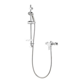
Concealed/exposed concentric valve with adjustable kit
Hide thumbs
Also See for SIERRA:
- Installation and user manual (16 pages) ,
- Installation and user manual (16 pages)

Related Manuals for Aqualisa SIERRA


Summary of Contents for Aqualisa SIERRA
- Page 1 SIERRA CONCEALED/EXPOSED CONCENTRIC VALVE WITH ADJUSTABLE KIT INSTALLATION AND USER GUIDE...
-
Page 2: Table Of Contents
However should any parts be damaged or missing please contact your point of purchase. This does not affect your statutory rights. In addition if you require replacement parts please contact the Aqualisa customer helpline on 01959 560010 for assistance. -
Page 3: Warranty
WARRANTY Aqualisa products are supplied complete with a 1 year guarantee that can be upgraded by registering this product with Aqualisa. For details see: www.aqualisa.co.uk/warranty BEFORE YOU START This shower should be installed by a competent person in compliance with current Water Supply Regulations. -
Page 4: Installation Exposed
Pump Installation: PUMPS MUST NOT BE FITTED DIRECTLY TO A WATER MAIN. REFER TO PUMP MANUFACTURERS INSTALLATION GUIDELINES. Ensure there is adequate flow through the pump to activate the flow switches. Combination boiler: MUST have a minimum rating of 24kW (80,000 Btu) and be of the type fitted with a fully modulating gas valve. - Page 5 N.B. The inlet elbows are supplied at factory set 150mm centres. If required, the inlet centres can be adjusted by winding the elbows into the body to reduce the inlet centres, or out to increase the inlet centres. Once the wall surface has been finished, flush through the pipe work prior to trimming the length of the pipes to 18mm, measured from the finished wall surface.
-
Page 6: Installation Concealed
Fit the elbow cover plates, fixing nuts and copper olives over the pipe tails and insert the filtered washers into the elbows of the valve. Making sure the outlet is at the bottom and that the elbows align with the pipe tails, push the valve body onto the mounting bracket, and secure with the two grub screws using the 2.5mm hexagonal key (supplied). - Page 7 IMPORTANT: Servicing and Maintenance access To enable sufficient access for ease of installation, servicing and maintenance ensure: Hot and cold feeds to the inlet elbows of the valve are from falling or rising pipe work. (i.e. Elbow connections pointing Wall plate diameter upwards or downwards).
- Page 8 Construct hot and cold supply pipes to the proposed siting. Ensuring adequate provision to allow the water to discharge safely to waste, turn on the supplies to flush the system through. Attach pressure test equipment and pressure test the system in accordance with Water Supply Regulations.
- Page 9 Place valve body into position with elbows over the pipe tails and mark around the base where it sits on the mounting surface. Remove valve body, place mounting bracket in centre of the *Valve position outlined valve position* and mark outline points for fixing holes.
- Page 10 Using a suitable coupling connect pipework to the outlet of the valve body. N.B. The outlet connector can be repositioned to the top of the shower valve as required to suit plumbing arrangements. Simply swap with the blanking plug and ensure both are securely re-tightened.
-
Page 11: Fitting The Shower Kit
Fitting the Shower Kit - Wall Outlet BRASS WALL OUTLET DESCRIPTION Backnut Backnut Backnut washer Backnut Washer Wall Cover Plate Cover plate Wall Outlet Wall Wall outlet With rear access: Without rear access: Backnut Wall Backnut washer Cover plate Cover plate Wall Female fitting (not supplied) - Page 12 Connect the wall outlet to a suitable ½” female connector using PTFE tape or similar, to achieve a watertight seal. Temporarily cap off the wall outlet, open the shower valve and check for leaks. Without rear access Run pipework from the shower valve to the desired location for the wall outlet ensuring it terminates in a suitable ½”...
- Page 13 Fitting the Shower Kit - Rail Assembly ADJUSTABLE SHOWER KIT DESCRIPTION Wall Plug Upper Rail Bracket Short Wall Screw End Cap Handset Holder Handset Riser Rail Shower Hose - 1.5m Hose Restraint Lower Rail Bracket Long Wall Screw The top bracket is a floating bracket and can be positioned to suit existing screw holes (if required).
-
Page 14: Cartridge Temperature Adjustment
Attach the lower rail bracket onto the bottom of the rail. Slide the rail assembly up through the upper rail bracket. Align the small hole in the rail with the lower rail bracket. Secure the lower rail bracket to the wall, using the long wall screw. -
Page 15: Cleaning The Thermostatic Cartridge
to deliver 38°C when the temperature knob is set to the 38°C position. In this case, you can adjust the cartridge to change the outlet water temperature to suit your requirements. This can be adjusted whilst using a digital thermometer and following the below instructions. 1. - Page 16 3. Push the black release tabs outward, pulling the flow handle forward at the same time (see Fig 1). Care should be taken not to break the release tabs. 4. Remove the retaining nut using a suitable spanner. Prior to removing the cartridge, take note of it’s orientation as it must be refitted the same way.
-
Page 17: User Instructions
For a cooler temperature - rotate clockwise. For a warmer temperature -rotate anticlockwise. N.B. With all Sierra shower valves fitted to combination boiler systems, it may be necessary to adjust the flow control knob and reduce the flow to achieve a comfortable showering temperature. -
Page 18: General Cleaning
3. To select the desired spray pattern rotate the shower spray plate clockwise or anti-clockwise. Inlet filters The product is protected by inlet filter washers located in the inlet elbow connections. GENERAL CLEANING Whilst modern plating techniques are used in the manufacture of these fittings, the plating will wear if not cleaned properly. - Page 19 Only hot or cold Partially closed stop or service valve Open stop or service valve. water from the in water supply pipework to the shower valve shower valve. outlet. Inlet filter is partially blocked. Clean or replace, flush through pipework before refitting. Inlet water supplies are reversed Check the connections are the (hot to cold supply).
- Page 20 Please note that calls may be recorded for training and quality purposes. The company reserves the right to alter, change or modify the product specifications without prior warning. ™ Trademark of Aqualisa Products Limited. Part No: 704451 Issue 03 July 19...
Need help?
Do you have a question about the SIERRA and is the answer not in the manual?
Questions and answers