Table of Contents
Advertisement
Quick Links
USER MANUAL
NI roboRIO
RIO Device for Robotics
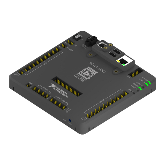
The NI roboRIO is a portable reconfigurable I/O (RIO) device that is used to design control,
robotics, and mechatronics systems.
This document contains pinouts, connectivity information, dimensions, and mounting
instructions for the NI roboRIO. The NI roboRIO provides the I/O shown in the following
figure and connects to a host computer over USB and 10/100 Ethernet.
1. Digital input and output (DIO) port
2. RS-232 port
3. I2C port
4. CAN port
5. Power connector
6. USB Device port
7. USB Host retention mount
8. USB Host ports
9. Ethernet port
Figure 1. NI roboRIO Features
5
6
INPUT
INPUT
7-16V
7-16V
CAN
CAN
4
L (GRN)
L (GRN)
H (YEL)
H (YEL)
3.3V SDA
3.3V SDA
3
2 2
I I
C C
SCL
SCL
2
RS-232
RS-232
TXD
TXD
RXD
RXD
1
33
33
RELAY
RELAY
RSL
RSL
0 0
1 1
S S
FWD
FWD
5V
5V
REV
REV
S S
18
17
7
8
9
10
POWER
POWER
STATUS
STATUS
SPI
SPI
RADIO
RADIO
14
COMM
COMM
CS0
CS0
SCLK
SCLK
CS1
CS1
MODE
MODE
MOSI
MOSI
5V
5V
MISO
MISO
CS2
CS2
NI roboRIO
NI roboRIO
CS3
CS3
3.3V
3.3V
1 1
Y Y
Z Z
X X
ACCELEROMETER
ACCELEROMETER
ANALOG IN
ANALOG IN
RESET
RESET
USER
USER
2 2
3 3
0 0
1 1
2 2
3 3
S
S
5V
5V
16
15
10. Serial peripheral interface bus (SPI) port
11. LEDs
12. Pulse-width modulation (PWM) port
13. myRIO Expansion Port (MXP)
14. MXP retention mount
15. User and Reset buttons
16. Analog input (AI) port
17. Relay port
18. Robot signal light (RSL) port
11
RSL
RSL
12
13
S
S
6V
6V
Advertisement
Table of Contents

Related Manuals for National Instruments roboRIO


Summary of Contents for National Instruments roboRIO
- Page 1 USER MANUAL NI roboRIO RIO Device for Robotics The NI roboRIO is a portable reconfigurable I/O (RIO) device that is used to design control, robotics, and mechatronics systems. This document contains pinouts, connectivity information, dimensions, and mounting instructions for the NI roboRIO. The NI roboRIO provides the I/O shown in the following figure and connects to a host computer over USB and 10/100 Ethernet.
-
Page 2: Table Of Contents
Converting Raw Data Values to Voltage.................17 Front Panel Buttons.........................17 Reset Button........................17 User Button........................18 LED Indications........................18 Power LED........................18 Status LED........................18 Radio LED........................19 Comm LED........................19 Mode LED........................20 RSL (Safety) LED......................20 Physical Dimensions....................... 21 2 | ni.com | NI roboRIO User Manual... -
Page 3: Safety Information
Perfboard........................24 Method Two: Using Cable Ties to Secure One Corner of the NI roboRIO to Perfboard........................26 Method Three: Using Screws to Secure the Bottom of the NI roboRIO to a Metal Plate.......................... 29 Compatible USB and Ethernet Cables..................29 Warranty..........................30 Worldwide Support and Services.................... -
Page 4: Setting Up The Ni Roborio
The NI roboRIO requires an external power supply that meets the specifications in the Power Requirements section of the NI roboRIO Specifications. The NI roboRIO filters and regulates the supplied power and provides power for all of the I/O and user voltage. The NI roboRIO has one layer of reverse-voltage protection. -
Page 5: Powering On The Device
Turn on the power supply. Powering On the Device The NI roboRIO runs a power-on self test (POST) when you apply power to the device. During the POST, the Power and Status LEDs turn on. When the Status LED turns off, the POST is complete. -
Page 6: User Power
C, SPI, and the MXP. Input Voltage Brownout Behavior The NI roboRIO input voltage range is 7 V to 16 V. The input voltage monitoring circuit monitors the voltage on the input voltage pin. When the input voltage drops to between 4.5 V... -
Page 7: Pinouts
6.8 V, the NI roboRIO enters brownout mode with a staged response, as the following table describes. Table 2. NI roboRIO Input Voltage Brownout Behavior Input Voltage Stage Behavior Range 6.3 V to 6.8 V The +6 V voltage rail starts to drop. -
Page 8: Mxp
+3.3 V power output. DIO <0..15> DGND Input or Output General-purpose digital lines with 3.3 V output, 3.3 V-/5 V-compatible input. Refer to the DIO, PWM, and Relay Lines section for more information. 8 | ni.com | NI roboRIO User Manual... -
Page 9: Can Port
H (YEL) Input/Output CAN bus differential high signal. Note The NI roboRIO contains an internal 120 Ω termination resistor between L (GRN) and H (YEL). C Port The following figure and table describe the I C port pins and signals. -
Page 10: Rs-232 Port
UART and RS-232 Lines section for more information. — Reference for digital lines. DIO Port The following figure and table describe the DIO port pins and signals. Figure 8. DIO Port Pinout 10 | ni.com | NI roboRIO User Manual... -
Page 11: Rsl Port
RSL current is limited at 120 mA. — Reference for S. Relay Port The following figure and table describe the Relay port pins and signals. Figure 10. Relay Port Pinout NI roboRIO User Manual | © National Instruments | 11... -
Page 12: Ai Port
Output +5 V power output. — Reference for AI and +5 V power. PWM Port The following figure and table describe the PWM port pins and signals. Figure 12. PWM Port Pinout 12 | ni.com | NI roboRIO User Manual... -
Page 13: Spi Port
To minimize noise on analog measurement channels, use the ground reference of the corresponding port. For example, when you are using AI, the measurement should reference the GND of the AI port. NI roboRIO User Manual | © National Instruments | 13... -
Page 14: Interfaces
Interfaces AI Channels The NI roboRIO has AI channels on the MXP and on the AI port. The channels are multiplexed to a single analog-to-digital converter (ADC) that samples all channels. The MXP and the AI port each has four single-ended AI channels, AI0-AI3, which you can use to measure 0 V to 5 V signals. -
Page 15: Dio, Pwm, And Relay Lines
You can program all MXP DIO lines and on-board DIO lines individually as inputs or outputs. Secondary digital functions include SPI, I C, PWM, and quadrature encoder input. Refer to the NI roboRIO software documentation for information about configuring the behavior of the DIO lines. NI roboRIO User Manual | © National Instruments | 15... -
Page 16: Uart And Rs-232 Lines
You can add a stronger resistor to a DIO line to cause it to float in the opposite direction. UART and RS-232 Lines The NI roboRIO has one UART connected to the UART lines on the MXP and one UART connected to the RS-232 port. -
Page 17: Converting Raw Data Values To Voltage
In safe mode, the NI roboRIO launches only the services necessary for updating configuration and installing software. When the NI roboRIO is in safe mode, you can communicate with it by using the serial lines on the RS-232 serial port. You must configure your serial-port terminal program with the following settings: •... -
Page 18: User Button
The Status LED is a single-color yellow LED. The Status LED is off during normal operation. The NI roboRIO runs a power-on self test (POST) when you apply power to the device. During the POST, the Power and Status LEDs turn on. When the Status LED turns off, the POST is complete. -
Page 19: Radio Led
Table 16. Comm LED Indications Color State Indication Green and Red disabled. Green Solid Green enabled. Solid Red enabled. Yellow Solid Green and Red enabled. NI roboRIO User Manual | © National Instruments | 19... -
Page 20: Mode Led
Mode LED The Mode LED is a tri-color red/green/yellow LED that indicates the mode of the NI roboRIO outputs, as shown in the following table. Table 17. Mode LED Indications Color State Indication Green and Red disabled. Green Solid Green enabled. -
Page 21: Physical Dimensions
Physical Dimensions The following figures describe the physical dimensions of the NI roboRIO enclosure and its features. Figure 19. NI roboRIO Dimensions, Primary Side 135.47 mm (5.333 in.) 132.61 mm (5.221 in.) INPUT 129.83 mm (5.111 in.) 7-16V 130.72 mm (5.147 in.) 129.21 mm (5.087 in.) - Page 22 Figure 20. NI roboRIO Dimensions, Primary Side LEDs 143.18 mm (5.637 in.) INPUT 7-16V 128.51 mm (5.059 in.) 123.51 mm (4.862 in.) 116.01 mm (4.567 in.) 111.01 mm (4.370 in.) 106.01 mm (4.173 in.) NI roboRIO 98.51 mm (3.878 in.)
- Page 23 8.09 mm (0.319 in.) 0.0 mm (0 in.) Figure 22. NI roboRIO Dimensions, Side 34.43 mm (1.355 in.) 32.19 mm (1.267a in.) 22.76 mm (0.896 in.) 5.71 mm (0.225 in.) NI roboRIO User Manual | © National Instruments | 23...
-
Page 24: Mounting The Ni Roborio
Method One: Using Cable Ties to Secure One Edge of the NI roboRIO to Perfboard The following figures show how to secure one edge of the NI roboRIO to perfboard. Figure 23. Step 1 to Secure One Edge of the Device... - Page 25 Figure 24. Step 2 to Secure One Edge of the Device Figure 25. Step 3 to Secure One Edge of the Device NI roboRIO User Manual | © National Instruments | 25...
-
Page 26: Method Two: Using Cable Ties To Secure One Corner Of The Ni Roborio To Perfboard
Method Two: Using Cable Ties to Secure One Corner of the NI roboRIO to Perfboard The following figures show how to secure one corner of the NI roboRIO to perfboard. Figure 27. Step 1 to Secure One Corner of the Device... - Page 27 Figure 28. Step 2 to Secure One Corner of the Device Figure 29. Step 3 to Secure One Corner of the Device NI roboRIO User Manual | © National Instruments | 27...
- Page 28 Figure 30. Step 4 to Secure One Corner of the Device Figure 31. Step 5 to Secure One Corner of the Device 28 | ni.com | NI roboRIO User Manual...
-
Page 29: Method Three: Using Screws To Secure The Bottom Of The Ni Roborio To A Metal Plate
NI roboRIO to a Metal Plate The following figure shows how to secure the bottom of the NI roboRIO to a metal plate using the built-in 4-40 screw holes. The length of the screws required depends on the thickness of the plate you use. -
Page 30: Warranty
Ethernet cables is 30.0 m (98.43 ft). Warranty For customers other than private individual users in the EU: The NI roboRIO is warranted against defects in materials and workmanship for a period of three years from the date of shipment, as evidenced by receipts or other documentation. NI will, at its option, repair or replace equipment that proves to be defective during the warranty period. - Page 31 Other product and company names mentioned herein are trademarks or trade names of their respective companies. For patents covering National Instruments products/technology, refer to the appropriate location: Help»Patents in your software, the file on your media, or the National Instruments Patent Notice at .
Need help?
Do you have a question about the roboRIO and is the answer not in the manual?
Questions and answers