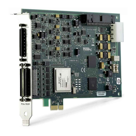
National Instruments R Series User Manual
Usb multifunction rio with kintex-7 160t fpga
Hide thumbs
Also See for R Series:
- User manual (72 pages) ,
- Getting started manual (12 pages) ,
- User manual (14 pages)
Table of Contents
Advertisement
Quick Links
USER MANUAL
NI USB-7856R OEM
R Series for USB Multifunction RIO with Kintex-7 160T FPGA
Français
This document provides dimensions, connectivity information, and pinouts for the National
Instruments USB-7856R OEM device.
Caution National Instruments makes no product safety, electromagnetic
compatibility (EMC), or CE marking compliance claims for NI USB-7856R OEM
device. The end-product supplier is responsible for conformity to any and all
compliance requirements.
Caution Do not operate the NI USB-7856R OEM device in a manner not
specified in this user manual. Product misuse can result in a hazard. You can
compromise the safety protection built into the product if the product is damaged in
any way. If the product is damaged, return it to National Instruments for repair.
Hardware Overview
The following high-level block diagram represents the NI USB-7856R OEM device.
日本語
Deutsch
ni.com/manuals
한국어
简体中文
Advertisement
Table of Contents

Summary of Contents for National Instruments R Series
- Page 1 Product misuse can result in a hazard. You can compromise the safety protection built into the product if the product is damaged in any way. If the product is damaged, return it to National Instruments for repair. Hardware Overview...
- Page 2 Figure 1. NI USB-7856R OEM Device Block Diagram DIO (x16) 40 MHz Flash Overvoltage Memory Protection DIO (x16) Overvoltage Protection DIO (x16) Overvoltage AI (x8) Protection Kintex-7 NI ASIC Data/ FPGA Address/ Control +5 V FPGA Overvoltage Temperature Reference Protection AO (x8) Overvoltage Protection...
-
Page 3: Parts Locator
C&K (E101J1AQE2) The following table lists and describes the I/O connectors on the NI USB-7856R OEM device. Refer to the connector manufacturer for information about using and matching these connectors. NI USB-7856R OEM User Manual | © National Instruments | 3... - Page 4 Table 2. NI USB-7856R OEM Device Connectors Connector Description Reference Designator Manufacturer AI, AO 50-position header 3M (N2550-6002RB) 34-position header 3M (N2534-6002RB) External LED 7-position header FCI 68000-107LF 4 | NI USB-7856R OEM User Manual | ni.com...
- Page 5 Dimensions 2X 6.675 (169.55) 2X 6.435 (163.46) 6.263 (159.08) 2X 6.055 (153.81) 2X 2.863 (72.72) 2X .175 (4.45) .000 (0) .119 (3.02) NI USB-7856R OEM User Manual | © National Instruments | 5...
- Page 6 3.812 (96.82) 6.500 (165.1) 2.688 (68.28) 5.830 (148.08) Note Visit for more information about the dimensions of ni.com/dimensions the NI USB-7856R OEM device, including two-dimensional drawings and three- dimensional models. Note The NI USB-7856R OEM device has plated mounting holes that can act as chassis ground.
-
Page 7: Analog Input
Figure 3. Figure 3. Connecting Referenced Single-Ended Signals to the NI USB-7856R OEM Device Overvoltage Protection PGIA AI– Overvoltage Protection – AISENSE Overvoltage Protection AIGND NI USB-7856R OEM NI USB-7856R OEM User Manual | © National Instruments | 7... -
Page 8: Connecting Differential Voltage Signals
To connect non-referenced single-ended voltage signals to the NI USB-7856R OEM device, you must connect the voltage ground signal to AI SENSE in order to keep the common-mode voltage in the specified range, as shown in Figure 4. Figure 4. Connecting Non-Referenced Single-Ended Signals to the NI USB-7856R OEM Device Overvoltage Protection PGIA... -
Page 9: Analog Output
10 MHz signal frequencies. Each connector has selectable logic levels that you can configure as 1.2 V, 1.5 V, 1.8 V, 2.5 V, or 3.3 V. You can configure each channel as input or output. NI USB-7856R OEM User Manual | © National Instruments | 9... - Page 10 The VI can then set the DIO lines to any power-on state. National Instruments recommends performing signal integrity measurements to test the effect of signal routing with the cable and connection accessory for your application.
- Page 11 V) and 3 and the negative connection. To connect the remaining LEDs, refer to Table 3. National Instruments recommends that you limit the current to 10 mA per LED. You can limit this current by using external resistors, as shown in Figure 9.
-
Page 12: Power Switch
Figure 10. Attaching External LEDs OEM (On-Board) +5 V External Resistor External Power Switch Use the power switch to power the NI USB-7856R OEM device on and off. The following figure shows the pins on the power switch and power circuitry. Figure 11. -
Page 13: Power Source
Caution Never connect the +5 V power terminals to analog or digital ground or any other voltage source on the NI USB-7856R OEM device or any other device. Doing so can damage the device and the computer. National Instruments is not liable for damage resulting from such a connection. -
Page 14: Worldwide Support And Services
Refer to the LabVIEW FPGA Module Help for more information about downloading an FPGA VI to the flash memory. Worldwide Support and Services The National Instruments website is your complete resource for technical support. At ni.com/ support you have access to everything from troubleshooting and application development self- help resources to email and phone assistance from NI Application Engineers. - Page 15 512 795 8248. For telephone support outside the United States, visit the Worldwide Offices section of ni.com/niglobal to access the branch office websites, which provide up-to- date contact information, support phone numbers, email addresses, and current events. NI USB-7856R OEM User Manual | © National Instruments | 15...
- Page 16 Other product and company names mentioned herein are trademarks or trade names of their respective companies. For patents covering National Instruments products/technology, refer to the appropriate location: Help»Patents in your software, the file on your media, or the National Instruments Patent Notice at .


Need help?
Do you have a question about the R Series and is the answer not in the manual?
Questions and answers