National Instruments PXIe-4339 User Manual And Specifications
8 ch, 24-bit, bridge and voltage input module, rack-mount terminal block
Hide thumbs
Also See for PXIe-4339:
- User manual (49 pages) ,
- Calibration procedure (30 pages) ,
- Installation manual (20 pages)
Table of Contents
Advertisement
Quick Links
USER GUIDE AND TERMINAL BLOCK
SPECIFICATIONS
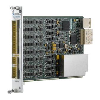
NI PXIe-4339 and RM-4339
NI PXIe-4339, 8 Ch, 24-Bit, Bridge and Voltage Input Module,
RM-4339 Rack-Mount Terminal Block
This document explains how to install, configure, and set up the NI PXIe-4339 SC Express
universal bridge module and RM-4339 rack-mount terminal block. Driver support for the
NI PXIe-4339 was first available in NI-DAQmx 14.2. Driver support for the RM-4339 was first
available in NI-DAQmx 14.5. For the list of devices supported by a specific release, refer to the
NI-DAQmx Readme, available on the version-specific download page or installation media.
The keying of these terminal blocks prevents them from connecting to other
Note
modules that could be damaged by the voltage present on the terminal block.
However, you should only use these terminal blocks with their supported modules.
Contents
Electromagnetic Compatibility Guidelines .............................................................................. 2
What You Need to Get Started ................................................................................................. 3
Installation ................................................................................................................................ 4
Install the Software ........................................................................................................... 4
Unpack and Install the Module......................................................................................... 4
Unpack and Install the Rack-Mount Terminal Block, Chassis, and Cables..................... 6
RM-4339 Positions ................................................................................................................... 10
Shared Resources.............................................................................................................. 10
CAL IN ..................................................................................................................... 11
CAL BIAS ................................................................................................................ 11
In-Situ Calibration .................................................................................................... 11
EXT PWR................................................................................................................. 13
Excitation/External Power........................................................................................ 13
Position Resources............................................................................................................ 14
RJ50 .......................................................................................................................... 14
Status LED................................................................................................................ 15
PFI0 .......................................................................................................................... 15
External Shunt .......................................................................................................... 16
AO 0..7 ..................................................................................................................... 18
Position Switching.................................................................................................... 19
Advertisement
Table of Contents

Related Manuals for National Instruments PXIe-4339


Summary of Contents for National Instruments PXIe-4339
-
Page 1: Table Of Contents
NI PXIe-4339, 8 Ch, 24-Bit, Bridge and Voltage Input Module, RM-4339 Rack-Mount Terminal Block This document explains how to install, configure, and set up the NI PXIe-4339 SC Express universal bridge module and RM-4339 rack-mount terminal block. Driver support for the NI PXIe-4339 was first available in NI-DAQmx 14.2. -
Page 2: Electromagnetic Compatibility Guidelines
To minimize interference with radio and television reception and prevent unacceptable performance degradation, install and use this product in strict accordance with the instructions in the product documentation. 2 | ni.com | NI PXIe-4339 and RM-4339 User Guide and Terminal Block Specifications... -
Page 3: What You Need To Get Started
To ensure the specified EMC performance, operate this product only with Caution shielded cables and accessories. What You Need to Get Started To set up and use the RM-4339 rack-mount terminal block with the NI PXIe-4339 module, you need the following items: • Hardware –... -
Page 4: Installation
Make sure the chassis is powered off. Connect the power cord to your chassis and then plug it into the power supply receptacle before installing the NI PXIe-4339. The power cord grounds the chassis and protects it from electrical damage while you install the module. - Page 5 Secure the module to the chassis using the front-panel captive screws, shown in Figure 2. Tighten the screws to 0.31 N · m (2.7 lb · in.). Figure 2. Installing NI PXIe-4339 Modules Captive Screws NI PXIe-4339 and RM-4339 User Guide and Terminal Block Specifications | © National Instruments | 5...
-
Page 6: Unpack And Install The Rack-Mount Terminal Block, Chassis, And Cables
To install the rack-mount terminal block into the rack, complete the following steps while referring to Figure 3. Place the RM-4339 in the desired position. Install and tighten the four rack-mounting screws. 6 | ni.com | NI PXIe-4339 and RM-4339 User Guide and Terminal Block Specifications... - Page 7 SCAL-4339 Shunt Calibration Accessory PFI BNC Cable RJ50 (8) Cable Connectors * Refer to the NI PXIe-4339 User Manual for more information regarding wide bandwidth analog output. NI PXIe-4339 and RM-4339 User Guide and Terminal Block Specifications | © National Instruments | 7...
- Page 8 Install the bias resistors. Refer to the section for more information. Install the 4-pin COMBICON cable into the RM-4339. Connect the chassis ground wire to the chassis ground screw. 8 | ni.com | NI PXIe-4339 and RM-4339 User Guide and Terminal Block Specifications...
- Page 9 Calibration Input 2-Position COMBICON Cable 16 Chassis Ground Cable Screw the two standoffs into the NI PXIe-4339 module. Tighten the standoffs to 1.30 N · m (11.5 lb · in.). Connect the male end of the SH96-96-2 cable to the RM-4339 and tighten the two jack screws to 0.90 N ·...
-
Page 10: Rm-4339 Positions
RM-4339, which are also labeled A, B, and C. Connectors within one of these positions connect to the same NI PXIe-4339 module. Figure 5 shows the location of the connectors on the front and rear of the RM-4339. -
Page 11: Cal In
The calibration data can be used to compensate for changes in the hardware, NI PXIe-4339 and RM-4339 User Guide and Terminal Block Specifications | © National Instruments | 11... - Page 12 NI PXIe-4339. Instead these results can be applied to the test setup, test results, or to the NI PXIe-4339 programmatically. To assist you with starting development of an application with in-situ calibration, an example program is available for download from the NI Community.
-
Page 13: Ext Pwr
RJ50 connector. When connected, EX+ is connected to EXT PWR+ and EX- is connected to the ground of the RM-4339. You can configure each channel independently to either connect to EXT PWR, to the excitation voltage provided by the NI PXIe-4339, or to not be connected to any reference (floating). -
Page 14: Position Resources
Refer to Table 5 for signal names and descriptions, and the correlation to the pin numbers of the RJ50 (10p10c) modular plug. Refer to Figure 8 for default switch positions. 14 | ni.com | NI PXIe-4339 and RM-4339 User Guide and Terminal Block Specifications... - Page 15 * NI does not recommend using an RJ45 cable with the RM-4339 as it can physically damage pins 1 and 10 on the RJ50 connector. : Refer to Figure 8 for default positions. Note NI PXIe-4339 and RM-4339 User Guide and Terminal Block Specifications | © National Instruments | 15...
-
Page 16: Status Led
Status LED The green status LED, when lit, indicates a position is connected to a powered NI PXIe-4339 module. The location of the Status LED is shown in Figure 5. PFI0 The PFI0 connector provides a female BNC connection to the PFI trigger line of the NI PXIe-4339. - Page 17 SCAL-4339 Case Shunt Calibration Resistor (8x user supplied) Mechanical Refer to the section for information about the required resistor lead diameter, spacing, and depth. NI PXIe-4339 and RM-4339 User Guide and Terminal Block Specifications | © National Instruments | 17...
- Page 18 The use of the SCAL-4339 Shunt Calibration Accessory does not prevent the built-in SCA resistor on the RM-4339 from being used, however the built-in resistor and the user provided resistor cannot be selected simultaneously. 18 | ni.com | NI PXIe-4339 and RM-4339 User Guide and Terminal Block Specifications...
- Page 19 AO4+ Analog output channel 4 AO5+ Analog output channel 5 AO6+ Analog output channel 6 AO7+ Analog output channel 7 AOGND Analog output ground NI PXIe-4339 and RM-4339 User Guide and Terminal Block Specifications | © National Instruments | 19...
-
Page 20: Position Switching
The RM-4339 provides software controlled switching to allow you to programmatically control the additional features the RM-4339 adds to the NI PXIe-4339. Each of the three positions is independently controlled by its corresponding NI PXIe-4339. Within a single position, each channel can be configured independently through NI-DAQmx. - Page 21 To PXIe-4339 50 kΩ SCB_50k 100 kΩ SCB_100k 100 kΩ AI− AI− CAL_IN+ CAL_IN− Shared by all positions (A, B, C) SCAL-4339 User Defined NI PXIe-4339 and RM-4339 User Guide and Terminal Block Specifications | © National Instruments | 21...
-
Page 22: Quarter-Bridge Completion And Shunt Calibration
Quarter-Bridge Completion and Shunt Calibration The RM-4339 provides software selectable quarter-bridge completion resistors that enable the NI PXIe-4339 to be used with quarter-bridge strain gages. You can select 120 Ω, 350 Ω or 1 kΩ completion resistors. Quarter-bridge shunt calibration resistors are also provided on the RM-4339. These resistors are labeled SCB_50k and SCB_100k in the switch circuit diagram of Figure 8. -
Page 23: Confirm Sc Express Module Recognition
If your module or terminal block is not listed, press <F5> to refresh MAX. If the module is still not recognized, go to ni.com/support/ daqmx NI PXIe-4339 and RM-4339 User Guide and Terminal Block Specifications | © National Instruments | 23... - Page 24 Right-click the module name and select Self-Test. When the self-test completes, a verification message appears. If an error occurs, refer to ni.com/support/daqmx For information about sensors, go to ni.com/sensors 24 | ni.com | NI PXIe-4339 and RM-4339 User Guide and Terminal Block Specifications...
-
Page 25: Run Test Panels
Select NI-DAQmx Task and click Next. Select Acquire Signals. Select Analog Input, and the measurement type, such as Strain. Select the physical channel(s) to use and click Next. NI PXIe-4339 and RM-4339 User Guide and Terminal Block Specifications | © National Instruments | 25... -
Page 26: Use Your Ni Sc Express Device In An Application
For other examples, go to and enter the Info Code . For additional ni.com/info daqmxexp examples, refer to zone.ni.com 26 | ni.com | NI PXIe-4339 and RM-4339 User Guide and Terminal Block Specifications... -
Page 27: Removal
Make sure that the chassis is powered off before removing the module. Loosen the captive screws on the top and bottom of the module. NI PXIe-4339 and RM-4339 User Guide and Terminal Block Specifications | © National Instruments | 27... -
Page 28: Create A Simulated Device
Select the device from the list provided. Click OK. To simulate an accessory: Right-click the simulated NI PXIe-4339>>Configure... Select the Accessory from the Connector 0 drop down. Click OK. 28 | ni.com | NI PXIe-4339 and RM-4339 User Guide and Terminal Block Specifications... -
Page 29: More Information
The offset voltage specification of the RM-4339 is an additional offset error that should be added to the offset error of the NI PXIe-4339 to determine the total system offset error. NI PXIe-4339 and RM-4339 User Guide and Terminal Block Specifications | © National Instruments | 29... -
Page 30: Bridge Completion
Mean number of insertions before failure..........500 Channel configuration switches Switch type ..........Electromechanical relay, latching Expected switch life Mechanical........5 × 10 cycles Electrical ...........2 × 10 cycles 30 | ni.com | NI PXIe-4339 and RM-4339 User Guide and Terminal Block Specifications... -
Page 31: Connectors
Clean the hardware with a soft, nonmetallic brush. Make sure that the Caution hardware is completely dry and free from contaminants before returning it to service. NI PXIe-4339 and RM-4339 User Guide and Terminal Block Specifications | © National Instruments | 31... -
Page 32: Environmental Specifications
Operating ..........5 Hz to 500 Hz, 0.3 g Non-operating ...........5 Hz to 500 Hz, 2.4 g (Tested in accordance with IEC 60068-2-64. Non-operating test profile exceeds the requirements of MIL-PRF-28800F, Class 3.) 32 | ni.com | NI PXIe-4339 and RM-4339 User Guide and Terminal Block Specifications... -
Page 33: Safety
Measurement Categories CAT I and CAT O are equivalent. These test and measurement circuits are not intended for direct connection to the MAINS building installations of Measurement Categories CAT II, CAT III, or CAT IV. NI PXIe-4339 and RM-4339 User Guide and Terminal Block Specifications | © National Instruments | 33... -
Page 34: Ce Compliance
WEEE recycling center. For more information about WEEE recycling centers, National Instruments WEEE initiatives, and compliance with WEEE Directive 2002/96/EC on Waste and Electronic Equipment, visit ni.com/environment/ weee 34 | ni.com | NI PXIe-4339 and RM-4339 User Guide and Terminal Block Specifications... -
Page 35: World Wide Support And Services
Worldwide Offices section of to access the branch office websites, which ni.com/niglobal provide up-to-date contact information, support phone numbers, email addresses, and current events. NI PXIe-4339 and RM-4339 User Guide and Terminal Block Specifications | © National Instruments | 35... - Page 36 NI product. Refer to the Export Compliance Information at ni.com/legal/export-compliance for the National Instruments global trade compliance policy and how to obtain relevant HTS codes, ECCNs, and other import/export data. NI MAKES NO EXPRESS OR IMPLIED WARRANTIES AS TO THE ACCURACY OF THE INFORMATION CONTAINED HEREIN AND SHALL NOT BE LIABLE FOR ANY ERRORS.
Need help?
Do you have a question about the PXIe-4339 and is the answer not in the manual?
Questions and answers