Table of Contents
Advertisement
High-Speed Chip Shooter
KE-2070
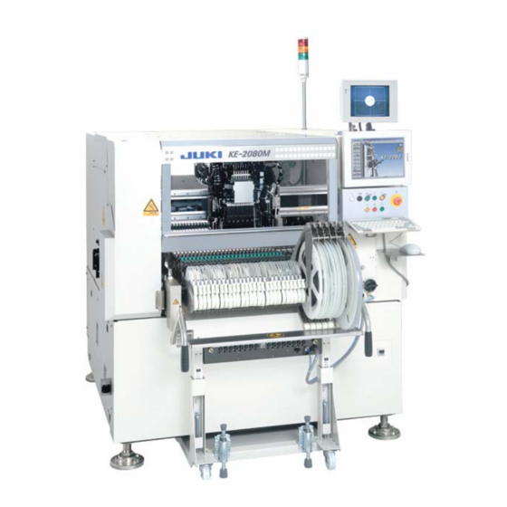
High-Speed Flexible Mounter
KE-2080/2080R
OPERATION MANUALⅠ
(For Operators)
Thank you for purchasing a product of our company.
CAUTION
In order to ensure safe use of KE-2070/ 2080/ 2080R, be sure to read
this Manual before using the machine.
After reading this Manual, keep it at a fixed location so that it will be
available at any time.
40052401
Advertisement
Table of Contents

Related Manuals for JUKI KE-2070


Summary of Contents for JUKI KE-2070
- Page 1 OPERATION MANUALⅠ (For Operators) Thank you for purchasing a product of our company. In order to ensure safe use of KE-2070/ 2080/ 2080R, be sure to read this Manual before using the machine. CAUTION After reading this Manual, keep it at a fixed location so that it will be available at any time.
- Page 2 (3) This manual is prepared with extreme care. However, if you have any question or find any error or omission in writing, contact our dealer or JUKI Corporation. (4) JUKI Corporation shall disclaim all the responsibility for any trouble resulting from the user's abnormal operation regardless of Item (3).
- Page 3 For the safe operation of machinery CAUTION All personnel engaged in the operation of the chip placer and its accessories (here after referred to as "machines") including the operators, service and maintenance personnel are required to read through this safety warning to make familiar with its handling to prevent accidents and injuries.
- Page 4 CAUTION Basic Matters of Precaution Be sure to read all documents included in this Manual and the attached booklet before using this machine. Also, keep this Manual carefully so as to be able to read it whenever necessary. Contents of this Manual include items that are not included in specifications of the machine purchased. The machine should be operated only by the operator who has learned how to run it.
- Page 5 Greasing Use the grease designated by JUKI only. To prevent the occurrence of an inflammation or rash, immediately wash the related portions if grease adheres to your eyes or other parts of your body.
- Page 6 1.6 “Updating the Drive C” of this Instruction Manual for how to update the drive C. Operations that require modification of the OS information are as follows: CAUTION − Version-up of KE-2070/80/80R system software and Flexline DB − Calibration of the touch panel − Addition of a printer −...
-
Page 7: Table Of Contents
Operation manualⅠContents For the safe operation of machinery Table of contents Introduction....................Overview of This Manual Notational Conventions Organization of This Manual Glossary Chapter 1 Overview of the Machine ............1-1 1.1. Overview of this machine ............. Configuration of the machine ............Chapter 2 Operation Procedure.............. -
Page 8: Introduction
Operation manualⅠ Introduction Overview of This Manual This is an introduction to PWB production with a KE-2070/2070C, 2080/2080R mounter. When you read and understand this manual thoroughly, you can use a created production program to produce PWBs. Refer to the attached “Operation Manual II (for Programmers and Administrators)” for how to create a production program or other settings. - Page 9 Operation manualⅠ Glossary LNC60 (Laser unit) Head This is a laser unit that finds This device picks up, centers and places a component. the center of a component LNC60 The machine is equipped with six “LNC60 heads” and (centers a component). (It one “IC head”...
-
Page 10: Chapter 1 Overview Of The Machine
Operation manualⅠ Chapter 1 Overview of the Machine 1.1. Overview of this machine This machine is a mounter that places electronic parts on an electronic circuit board on which solder is pasted or to which adhesive is applied. After the head picks up a component from a component supplying device (such as a tape feeder) and finds the center of the component, it places the component on the programmed placement coordinates of a board. -
Page 11: Configuration Of The Machine
Operation manualⅠ 1.2 Configuration of the machine Monitor ① Monitor This is a monitor for teaching operation. It ① ② displays an image shot by a camera. This is a liquid crystal monitor. It displays ② Operation panel ③ each operation screen. ③... -
Page 12: Chapter 2 Operation Procedure
Operation manualⅠ Chapter 2 Operation Procedure 2.1 Flow of PWB production The following flow chart indicates the operation flow from power-on to the end of PWB production. To perform a routine PWB production, follow the operations in order: No. 1, No.2, No. 3, No. -
Page 13: Overview Of Operations
Operation manualⅠ 2.2 Overview of operations Step 1 Turn on the power of the main unit. ① Check to see if there is no substance such as a board or tool inside the machine. ② Rotate the main switch to the right to check the air meter (pressure gauge). Turn the main switch to the right by 90 degrees. - Page 14 Operation manualⅠ Step 2 Warm up the machine. If you warm up the machine before PWB production, the machine can start PWB production stably. ① Select the button from the main screen. ② The “Warming-up” screen appears. Make the settings for the warming-up conditions.
- Page 15 Operation manualⅠ Step 3 Load a production program. ① Select the button from the main screen. ② The “Open” dialog box appears on the screen. Select the desired production program, and select the <Open> button. <Procedure> Select a folder. Select a file. Select the <Open>...
- Page 16 Operation manualⅠ Step 4 Select the PWB production screen. ① Select the button from the main screen. ② The PWB production screen appears. If you have to make various settings such as setting of the conveyor width according to a PWB to be produced ⇒ Go to “Step 5.” If you do not have to make any settings such as setting of the conveyor width ⇒...
- Page 17 Operation manualⅠ Step 5 Set a board. When you change the size of a board, you have to adjust the conveyor width and the position of the pusher X to the size of a board. This manual describes how to adjust the standard shape reference machine. Refer to Section 2.7.1.3 “Pin reference adjustment”...
- Page 18 Operation manualⅠ <Step 2> Check and adjust the stopper position. ① Select the [Production function] command from the menu bar of the “Production” screen, and then the [Quick Setup] command. ② The “Quick Setup” screen appears. Select the <Independent> button. ③...
- Page 19 Operation manualⅠ <Step 3> Set the support pins. ① Set the support pins on the support table according to the shape of the board. * Check to see if any substance such as a chip is not stuck to the bottom of the support pin. * To mount components on both sides of a board, set the support pins so that no pin can...
- Page 20 Operation manualⅠ <Step 4> Adjust the pusher X and the pusher Y. ① Select the <Side clamp> button on the “Independent control of conveyor” dialog box to operate the pusher X and the pusher Y. Select the <Side clamp> button. Operate the <ON>...
- Page 21 Operation manualⅠ <Step 5> Check the condition of the conveyor. Set a board on the IN buffer to check to see if it can be transported smoothly and continuously. Select the <PWB Conveyor> button on the “Quick Setup” dialog box. The “Control of conveyor”...
- Page 22 Operation manualⅠ <Step 6> Check the shape reference position and perform a teaching operation (adjustment of the position). After you change the stopper position in <Step 2>, you have to adjust the “shape reference position.” ① Load a board. (See <Step 5>.) ②...
- Page 23 Operation manualⅠ Step 6 Attach components to be used for PWB production on a component supplying device such as a tape feeder. Refer to the Operating Instructions of each component supplying device for how to attach components on it. Step 7 Install a tape feeder on the feeder bank.
- Page 24 Operation manualⅠ Step 8 Check the component pick-up position. Track the X and Y coordinates (component pick-up coordinates) and the Z coordinate (component pick-up height). ① 1. Select the “Supply Device” tab from the “Quick Setup” screen. 2. Select the <Pick Track Manual> button. ②...
- Page 25 Operation manualⅠ ④ After the system checks (teaches) all components, quit the “Quick Setup” dialog box. Select the <OK> button. ⑤ Select the <OK> button. ⑥ The “Production” screen reappears. 2− 14...
- Page 26 Operation manualⅠ Step 9 Perform PWB production. Enter the desired value in the “Planed No. of PWBs” field on the “Prod Control” screen, and then press the <START> switch. PWB production starts. (Refer to Section 2.8.2 “Production condition screen” of the “Operation Manual II”...
- Page 27 Operation manualⅠ Step 10 Quit the production screen. Select the button. When you select the <Save> button, the program changed at PWB production and the production management information are saved. Select the <OK> button. 2− 16...
- Page 28 Operation manualⅠ Step 11 Turn off the power of the main unit. ① Select the button from the main screen. When you select the <OK> button, the machine is restored into the initial state. When you press the <OK> button, the machine starts operating. WARNING To avoid risk of injury, never put your hand or head inside the machine.
-
Page 29: Chapter 3 Various Processes During Pwb Production
Operation manualⅠ Chapter 3 Various Processes During PWB Production This Chapter describes how to handle main errors that will occur during PWB production and a component run-out error. 3.1 When components run out (If the check box “Stop system when components run out”... -
Page 30: When Components Run Out (If The Check Box "Stop System When Components Run Out" Is Not Checked On The "Operation Option" Screen)
Operation manualⅠ 3.2 When components run out (If the check box “Stop system when components run out” is not checked on the “Operation option” screen) After the machine finishes placing all components that can be placed on boards, the following screen appears and the mounter stops temporarily. Error screen Causes of the error ①... -
Page 31: When A Mark Recognition Error Occurs
Operation manualⅠ 3.3 When a mark recognition error occurs Error screen Causes of the error ① Stained BOC mark ② A BOC mark is not within the inspection frame. ③ Input error of BOC mark coordinate data * An area fiducial mark causes the similar error. -
Page 32: When The Laser Sensor Is Stained
Operation manualⅠ 3.4 When the laser sensor is stained Error screen Causes of the error When the check box “Check Laser condition” on the “Production (Function2)” tab invoked from the “Operation option” screen, the system checks to see if the laser sensor window is stained when a board is loaded to the machine. -
Page 33: When An Error (La Recognition Error, Tombstone Error Or Irregularly-Shaped Component Error) Occurs
Operation manualⅠ 3.5 When an error (LA recognition error, tombstone error or irregularly-shaped component error) occurs Error screen Causes of the error An error occurs if the value specified in a production program is different from the value The error message measured with laser. -
Page 34: When A Vision Recognition Error Occurs
Operation manualⅠ 3.6 When a vision recognition error occurs Error screen Causes of the error ① A lead of a component is bent. ② A lead or ball of a component gets oxidized. ③ The supplied angle of a tray component is wrong. -
Page 35: When A Nozzle Error Occurs
Operation manualⅠ 3.7 When a nozzle error occurs Error screen Causes of the error ① The machine failed to attach/detach a nozzle. ② There is a foreign substance on the ATC plate. ③ The nozzle outer malfunctions. ④ The vacuum capability is lowered. How to handle an error 1) Select the “Mode”... -
Page 36: When A Feeder Float Error Is Detected
Operation manualⅠ 3.8 When a feeder float error is detected Error screen Causes of the error If the machine detects a feeder float error while it is performing PWB production (the XY-axes are moving), it is put in the pause state. -
Page 37: When A Cover Open Error Occurs
Operation manualⅠ 3.9 When a cover open error occurs Error screen Causes of the error ① The safety cover was opened while the machine was producing a PWB. ② The cover open sensor malfunctions. How to handle an error After closing the safety cover, press the <START> switch to resume the suspended PWB production. -
Page 38: When The Feeder Bank Moves Down (Only If An Overall Feeder Exchange Trolley Option Is Attached On The Machine)
Operation manualⅠ 3.10 When the feeder bank moves down (only if an overall feeder exchange trolley option is attached on the machine) Error screen Causes of the error ① The feeder bank moved down while the machine was producing a PWB. ②... -
Page 39: Pause For Protection Of A Component
Operation manualⅠ 3.11 Pause for protection of a component Error screen Causes of the error If a component that is set to be protected on the “Component data (Add Info.)” of a production program causes a recognition error, the machine temporarily stops. ①... -
Page 40: Continuous Pwb Production
Operation manualⅠ 3.12 Continuous PWB production If PWB production is aborted abnormally (an asynchronous event occurs or PWB production is aborted abnormally), you can resume PWB production by following the procedure below. However, this operation is available only after the machine picks up and places at least one component. - Page 41 Operation manualⅠ When you press the <START> switch on the “Processing before production begins” screen, the following screen appears. Select the <Execute> button and check to see if a component is “already placed” or “not placed” at the placement point on the vision monitor with your eyes. This button allows you to check the component placement point at which the machine will resume PWB...
- Page 42 ◆ Revision record Rev. Date Revised locations Revision contents Remarks Jan.2007 First edition Mar.2007 <For the Main Unit Ver.1.50> Revised <For the Main Unit Ver.2.00> Revised Dec.2008 <For KE-2080R> <For the Main Unit Ver.2.20> Jul.2009 P1-2 P2-5 P3-4,8 Revised <Added IS Ver2.00> Feb.2010 P2-2,17 <For the Main Unit Ver.2.50>...
- Page 43 MANUFACTURER INQUIRY 2-11-1, Tsurumaki, Tama-shi, Tokyo 206-8551, JAPAN PHONE: 81-42-357-2293 FAX: 81-42-357-2285 http://www.juki.co.jp/ Copyright © 2007-2013 JUKI CORPORATION The specification and appearance may be changed without notice. All rights reserved throughout the world. Original Instructions...
Need help?
Do you have a question about the KE-2070 and is the answer not in the manual?
Questions and answers
I hope you help me.