Table of Contents
Advertisement
KE KE KE KE‑ ‑ ‑ ‑ 2010/2020/2030/2040
2010/2020/2030/2040
2010/2020/2030/2040
2010/2020/2030/2040
INST
INSTALLATION
INST
INST
ALLATION GUIDE
ALLATION
ALLATION
GUIDE
GUIDE
GUIDE
JUKI CORPORATION
JUKI CORPORATION
JUKI CORPORATION
JUKI CORPORATION
ELECTRONIC ASSEMBLY &
ELECTRONIC ASSEMBLY &
ELECTRONIC ASSEMBLY &
ELECTRONIC ASSEMBLY &
TEST SYSTEMS DIVISION
TEST SYSTEMS DIVISION
TEST SYSTEMS DIVISION
TEST SYSTEMS DIVISION
SMT TRAINING CENTER
SMT TRAINING CENTER
SMT TRAINING CENTER
SMT TRAINING CENTER
Advertisement
Table of Contents

Related Manuals for JUKI KE-2000 Series


Summary of Contents for JUKI KE-2000 Series
- Page 1 JUKI CORPORATION JUKI CORPORATION JUKI CORPORATION JUKI CORPORATION ELECTRONIC ASSEMBLY & ELECTRONIC ASSEMBLY & ELECTRONIC ASSEMBLY & ELECTRONIC ASSEMBLY & TEST SYSTEMS DIVISION TEST SYSTEMS DIVISION TEST SYSTEMS DIVISION TEST SYSTEMS DIVISION SMT TRAINING CENTER SMT TRAINING CENTER SMT TRAINING CENTER SMT TRAINING CENTER...
- Page 2 ...
-
Page 3: Table Of Contents
KE2000 Installation Manual CONTENTS 1. Basic configuration and name of each part..................1 1-1. KE-2010/2020/2040........................... 1 1-2. KE-2030..............................2 Installing the main unit ..........................3 Detaching the packing materials from the machine ................4 3-1. Overall machine cover ......................... 4 3-2. - Page 4 KE2000 Installation Manual 12-3. Keyboard bracket ..........................31 12-4. HOD (Handheld operating device)....................31 12-5. Hand knob ............................31 12-5. Hand knob ............................32 12-6. Feed relay cable..........................32 12-7. Chip box ............................33 Interface with external equipment...................... 34 13-1. KE-2020/2040 ..........................34 13-2.
-
Page 5: Basic Configuration And Name Of Each Part
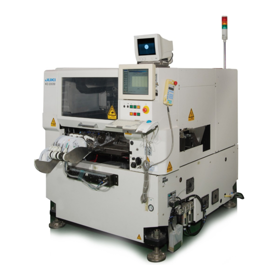
KE2000 Installation Manual Basic configuration and name of each part 1-1. KE-2010/2020/2040 1-1-1. Standard Machine Fig.1-1-1-1 Front view Fig.1-1-1-2 Right side view 1-1-2. CE Machine Fig.1-1-2-1 Front view Fig.1-1-2-2 Right side view (1) Vision monitor Track ball (2) LCD panel Signal light (3) HOD (Handheld Operating Device) unit Main switch... -
Page 6: Ke-2030
KE2000 Installation Manual 1-2. KE-2030 1-2-1. Standard Machine Fig.1-2-1-1 Front view Fig.1-2-1-2 Right side view 1-2-2. CE Machine Fig.1-2-2-1 Front view Fig.1-2-2-2 Right side view (1) Vision monitor Track ball (2) LCD panel Signal light (3) HOD (Handheld Operating Device) unit Main switch (4) Keyboard No-fuse circuit breaker... -
Page 7: Installing The Main Unit
KE2000 Installation Manual Installing the main unit <Procedure> Screw-in the adjusters to place the casters on the floor (ground) firmly before transporting or moving the main unit. Before moving the main unit using a forklift, be sure to put the fork under the main unit from its front, and lift it up and move it after checking that the fork protrudes sufficiently from the rear of the main unit. -
Page 8: Detaching The Packing Materials From The Machine
KE2000 Installation Manual Detaching the packing materials from the machine 3-1. Overall machine cover Detach the vinyl cover from the machine main unit. (This packing applies to only the machines shipped to the domestic market.) KE-2010, 2020, 2040 Dimensions of vinyl cover: 1800 (W) x 1700 (D) x 1500 (H) t 0.05 (Thickness) KE-2030... -
Page 9: Safety Cover
KE2000 Installation Manual 3-2. Safety cover Peel off the filament tapes stuck on the safety cover. Safety cover R Filament tapes Safety cover F Main unit Fig 3-2-1... -
Page 10: Transport Cover (Only Ce Machine)
KE2000 Installation Manual 3-3. Transport cover (only CE Machine) Peel off the filament tapes stuck on the transport cover. Transport cover Transport cover lid Filament tapes Fig 3-3-1 3-4. Pneumatic units Detach the air caps from the finger valve and drain bottle. Air cap For factory piping (air tube) Fig 3-4-1... -
Page 11: Feeder Relay Cable 8 (For Machines With Fixed Bank Specification Only)
KE2000 Installation Manual 3-5. Feeder relay cable 8 (For machines with fixed bank specification only) Peel off the filament tapes fixing the feeder relay tube and air tube. Filament tape Air tube Lower portion of main unit Connector bracket Feeder relay tube Fig 3-5-1... -
Page 12: Replacement Table Trolley
KE2000 Installation Manual 3-6. Replacement table trolley 3-6-1. Overall replacement table trolley Detach the air cap cover from the replacement table trolley. Feeder bank Air cab Overall Feeder Exchange trolley Fig 3-6-1-1 3-6-2. Feeder relay cable Peel off the filament tapes fixing the feeder relay tube and air tube. Filament Air tube Trolley frame... - Page 13 KE2000 Installation Manual 3-6-3. Trolley frame Detach the P.P. band fixing the feeder bank and trolley frame. Feeder bank P.P. band Overall Feeder Exchange trolley (Floor Trolley frame Fig 3-6-3-1...
-
Page 14: Adjusting The Transport Height And Leveling The Machine
KE2000 Installation Manual Adjusting the transport height and leveling the machine 4-1. KE-2010/2020/2040 <Procedure> 1. Detach the cover FB, cover RBC, cover RBR, and cover RBL (Fig 4-1-1). Detach the air cap put at the end of the rail (Fig 4-1-2,Fig 4-1-3). Cover RBL Cover RBC Cover FB... - Page 15 KE2000 Installation Manual 2. Loosen three hexagon socket head bolts of each adjuster. (Make sure that the adjust foot moves freely.) 3. When adjusters raised from adjuster (1), (3), (2), (4), (1), and so on in that order, this ensures relatively smooth raising of the machine level.
- Page 16 KE2000 Installation Manual Lock the adjust nuts. With the adjust nuts locked, check again that the scale on the level vial shows the set value ± 1. Tighten three hexagon socket head bolts of each adjuster. <CAUTION> If the unit may move due to the vibration during operation, attach the M8 X 30 hexagonal hole bolts B (3) and the M8 nuts C (3) packed with the unit.
-
Page 17: Ke-2030
KE2000 Installation Manual 4-2. KE-2030 <Procedure> 1. Detach the cover FBR, cover FBL, cover RBR30, cover RBCR30, cover RBCL30, and cover RBL30. Cover FBL30 Cover FBL Cover FBR Cover RBCR30 Cover FBR30 Cover RBCL30 Fig 4-2-1 Loosen three bolts A(see the fig 4-2-5) fixing the adjust bolt and adjust foot of each adjuster. - Page 18 KE2000 Installation Manual 3. Adjust the adjusters (1), (3), (4), and (6) to level the machine in the back and forth, and horizontal directions(see the fig 4-2-2). At this time, a level vial is placed on the hatching on the top of the base frame (see the fig 4-2-3) . (A level vial is placed on the transport base unit only for EXTRA machines.) Viewed from the top Transport base unit(EXTRA)...
-
Page 19: X-Y Unit
KE2000 Installation Manual X-Y unit 5-1. Detaching the X-axis frame fixing parts (For model 2030 only) Detach the stopper rubber fixing the X-axis frame and set-up caution tag. Fig 5-1-1 set-up caution tag To prevent the body from injury which can be caused by accidental activation of the machine , cut off the power to WARNING WARNING... -
Page 20: Detaching The Head Fixing Parts
KE2000 Installation Manual 5-2. Detaching the head fixing parts Detach the stopper rubber fixing the head and set-up caution tag. Fig 5-2-1 set-up caution tag To prevent the body from injury which can be caused by accidental activation of the machine , cut off the power to WARNING WARNING WARNING... -
Page 21: Head Unit
KE2000 Installation Manual Head unit 6-1. Detaching the packing materials Detach the air cap covering the overall head, the rust preventive paper sheet (Oji Paper Co., Ltd. KS-VC1 Ferro-bright u-35ss-1 (for plastic)) covering the lower portion of the head, and desiccating agent put under the OCC. Desiccating agent Rust preventive paper Fig 6-1-1... -
Page 22: Detaching The Head Unit Fixing Parts
KE2000 Installation Manual 6-2. Detaching the head unit fixing parts 6-2-1. Detaching the MNLA head Z-axis fixing parts SEMS cap x 2 (SL6030642TN) Set-up caution tag Z-axis stopper (E3007729000) Z-axis slide bracket Fig 6-2-1-1 Remove the SEMS cap screws (SL6030642TN) to detach the Z-axis stopper (E3007729000). - Page 23 KE2000 Installation Manual 6-2-2.Detaching the FMLA head Z-axis fixing parts 図6-2-2-1 Set-up caution tag Remove the SEMS cap screws (SL6042542TN) to detach the spacer (11100500). Make sure that the Z-axis slide bracket moves smoothly in the vertical direction. To prevent the body from injury which can be caused by accidental activation of the machine , cut off the power to WARNING WARNING...
-
Page 24: Board Transport Unit
KE2000 Installation Manual Board transport unit 7-1. Detaching the packing materials from the transport rail Peel off the filament tapes fixing the rail M and rail F, and detach the air cap put at the center of the transport rail. Filament tape ※ For only the model KE-2030, the rail is separated into four pieces, IN buffer, IN center station, OUT center station, and OUT buffer. -
Page 25: Center Station On The Y-Axis Drive Side (For Model 2030 Only)
KE2000 Installation Manual 7-3. Center station on the Y-axis drive side (For model 2030 only) Remove the band fixing the transport unit of the Y-axis drive side (front reference and rear reference, right side when viewed from the front) to detach the packing material put between the base bridge and transport base. -
Page 26: Unpacking The Supply Parts
KE2000 Installation Manual 7-4. Unpacking the supply parts Take out the backup pin (E20217150A0) and hand knob (E2206700000) from the packing carton box, and set them on the machine. Backup pin BU plate Hand knob Fig 7-4-1 ※Number of backup pins by model ●... -
Page 27: Atc Unit
KE2000 Installation Manual 8. ATC unit Detach the air cap from the ATC unit and the tie-up band fixing the ATC base and slide plate. Air cap Slide plate Tie-up band Hole ATC base Fig 8-1 CAL block Detach the air cap from the upper portion of the CAL block. Air cap CAL block Tape... - Page 28 KE2000 Installation Manual 11-1-2. CE Machine Prior to connecting the power cord, check to make sure that the power is not applied to the power supply circuit to be connected (in the form that DANGER DANGER DANGER DANGER the circuit breaker on the power distribution panel is open, etc.). Procedure <...
-
Page 29: Connecting The Compressed Air Tube
KE2000 Installation Manual Connecting the compressed air tube <Procedure> Connect the compressed air tube (φ12) coming from the factory to the finger valve. Turn the knob① of the finger valve to supply the compressed air to the mounter main unit. Pull the pressure regulation knob②... - Page 30 KE2000 Installation Manual Adjustment screw Regulator Air filter Mist seperator Window Fig 10-2 To prevent the body from injury which can be caused by accidental activation of the machine , cut off the power to WARNING WARNING WARNING WARNING the machine before starting to work. Check to make sure that a sufficient current-carrying pressure for air supply is secured in the factory.
- Page 31 KE2000 Installation Manual 11-2. 2010/2020/2040 11-2-1. Standard Machine Prior to connecting the power cord, check to make sure that the power is not applied to the power supply circuit to be connected (in the form that DANGER DANGER DANGER DANGER the circuit breaker on the power distribution panel is open, etc.).
-
Page 32: Connecting The Power Cord
KE2000 Installation Manual Connecting the power cord 11-1. 2010/2020/2040 11-1-1. Standard Machine Prior to connecting the power cord, check to make sure that the power is not applied to the power supply circuit to be connected (in the form that DANGER DANGER DANGER... - Page 33 KE2000 Installation Manual 11-2-2. CE Machine Prior to connecting the power cord, check to make sure that the power is not applied to the power supply circuit to be connected (in the form that DANGER DANGER DANGER DANGER the circuit breaker on the power distribution panel is open, etc.). Procedure <...
-
Page 34: Mounting The Accessories
KE2000 Installation Manual Mounting the accessories 12-1. Signal light 1)Insert the signal light through the hole in the top of the cover RUR. 2)Put the nuts and flat washers supplied with the machine Cover RUR as illustrated in the Figure shown to the right and secure the bracket. -
Page 35: Keyboard Bracket
KE2000 Installation Manual 12-3. Keyboard bracket 1) Secure the keyboard mounting plate of the keyboard bracket assembly to the main unit. 2) Connect the keyboard cable to the keyboard connector in the hole (upper) in the right side of the cover FUR. 3) Connect the track ball cable to the track ball connector in the hole (middle) in the right side of the cover FUR. -
Page 36: Hand Knob
KE2000 Installation Manual 12-5. Hand knob Place the hand knob on the groove (recessed part) on the top of the pulley cover on the right side of the main unit. Fig 12-5-1 12-6. Feed relay cable Connect the feeder relay cable and air tube coming from the connector bracket to the connectors on the main unit cover. -
Page 37: Chip Box
KE2000 Installation Manual 12-7. Chip box 12-7-1. KE-2010/2020/2040 Chip box (E910372900) Fig 12−7−1−1 12-7-2. KE-2030 ) Chip box (E5113729000,Left side Chip box (E5113729000,Right side Fig ... -
Page 38: Interface With External Equipment
KE2000 Installation Manual Interface with external equipment 13-1. KE-2020/2040 Fig 13-1-1.Left side view of the main unit Fig 13-1-2.Right side view of the main unit ① is the READY OUT (IN) connector (14-pin) to be connected to other equipment when operating the machine main unit in the on-line mode. The pin assignments may vary depending on the board transport direction, left to right and right to left, and are shown in Table 13-1-1 and Table 13-1-2. - Page 39 KE2000 Installation Manual Table 13-1-3 Pin assignments of the printer connector Signal name Connector type STROBE D-SUB 25P FEMALE BUSY SLCT AUTFD ERROR INIT SLCT IN...
-
Page 40: Ke-2010/2030
KE2000 Installation Manual 13-2. KE-2010/2030 Fig 13-2-1.Left side view of the main unit Fig 13-2-2.Right side view of the main unit 1) ① is the READY OUT (IN) connector (14-pin) to be connected to other equipment when operating the machine main unit in the on-line mode. The pin assignments may vary depending on the board transport direction, left to right and right to left, and are shown in Table 13-1-1 and Table 13-1-2. - Page 41 KE2000 Installation Manual Table 13-1-1 Pin assignments of the connector on the front left side of the main unit Connector type Signal name Signal name (Transport direction :left to right) (Transport direction :right to left) READY OUT + READY IN + READY IN - (GND) READY OUT - 206043-1...
-
Page 42: Connecting The Matrix Tray Changer (Mtc)
KE2000 Installation Manual Connecting the matrix tray changer (MTC) 14-1. Interface panel Connect the MTC power connector and signal connector to the interface panel on the right side of the main unit. Additionally, connect the air tube to the MTC air joint on the rear of the main unit. - Page 43 KE2000 Installation Manual The interface circuit diagrams of the READY OUT (IN) and BOARD AVAILABLE signals are shown in the Figure below. These signals conform to the SMEMA standard. READY OUT + READY OUT - BOAD AVAILABLE IN + BOAD AVAILABLE IN - 3.3K 1/4W +24V...
-
Page 44: Tr-4Sn
KE2000 Installation Manual 14-2. TR-4SN Mount the TR-4SN on the rear of the main unit. The positional relationship should be as shown in Figure 14-2-1. (Unit: mm) Home position Front of the main unit Rear of the main unit Outside view of TR-4SN mounting portions Fig 14-2-1. -
Page 45: Tr-6Sn And Tr-6Dn
KE2000 Installation Manual 14-3. TR-6SN and TR-6DN Mount the TR-6SN and TR-6DN on the right of the main unit. The positional relationship should be as shown in Figure 14-3-1. (Unit: mm) Rear of the main unit Home Position (Origin position) Fig 14-3-1. -
Page 46: Tr-5Sn And Tr-5Dn
KE2000 Installation Manual 14-4. TR-5SN and TR-5DN Mount the TR-6SN and TR-6DN on the rear of the main unit. The positional relationship should be as shown in Figure 14-4-1. (Unit: mm) Fig 14-4-1. Outside view of TR-5SN and TR-5DN mounting portions ※When installing the TR5SN/5DN to the main unit, detach the handle on the main unit rear cover first. -
Page 47: Checking The Machine Before Turning On The Power
KE2000 Installation Manual Checking the machine before turning on the power <Procedure> Check that the mounter main unit is leveled correctly. Check that the height of the transport rail satisfies the customer's requirements. Check that the adjuster lock nuts are secured firmly. Check that the dry air is supplied to the machine correctly. -
Page 48: Adjusting The Height Of The Overall Feeder Exchange Trolley (Optional)
KE2000 Installation Manual Adjusting the height of the overall feeder exchange trolley (optional) Always adjust the height of the overall feeder exchange trolley after the machine has been leveled correctly. <CAUTION> Do not fall down the replacement table while changing the caster plate mounting position. Doing so may cause the trolley handle to break. -
Page 49: Adding The Trolley Spacers (For Height Adjustment)
KE2000 Installation Manual 16-2. Adding the trolley spacers (For height adjustment) If the overall feeder exchange trolley does not enter the main unit due to inclined machine installation place (floor level of the machine installation factory) or low overall feeder exchange trolley height, it is necessary to adjust the height of the overall feeder exchange trolley by adding the trolley spacers (E2738721000). -
Page 50: Adjusting The Bank Valve Position
KE2000 Installation Manual The bank stopper mounting positions stated in Table 16-3-1 used reference. Bank stopper According to the actual installation status, the bank stopper needs to be mounted at a position where a large portion of the bank stopper is in contact with the trolley stopper Trolley stopper plate plate. - Page 51 ♦ ♦ ♦ ♦ Revision record Rev. Date Revised locations Revision contents FEB, 2000 Officially published as an English version 1.00 JULY,2001 All page • Specifications are subject to be changed without notice. Copyright © 2000 JUKI CORPORATION All rights reserved throughout the world.
- Page 52 CUSTOMER SUPPORT DEPT. SMT CENTER 2-11-1, Tsurumaki, Tama-shi, Tokyo 206-8551, JAPAN PHONE: 81-42-357-2298 FAX: 81-42-357-2297 http://www.juki.co.jp/ The specification and appearance may be changed without notice. Copyright © 2000-2010 JUKI CORPORATION All rights reserved throughout the world. 2010.08 Printed in Japan...
Need help?
Do you have a question about the KE-2000 Series and is the answer not in the manual?
Questions and answers