Sign In
Upload
Manuals
Brands
JUKI Manuals
Industrial Equipment
KE-2080
User Manuals: JUKI KE-2080 Place Machine
Manuals and User Guides for JUKI KE-2080 Place Machine. We have
3
JUKI KE-2080 Place Machine manuals available for free PDF download: Maintenance Manual, Operation Manual, Manual
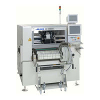
JUKI KE-2080 Maintenance Manual (100 pages)
High-Speed Chip Scooter
Brand:
JUKI
| Category:
Industrial Equipment
| Size: 8.03 MB
Table of Contents
Table of Contents
3
X-Y Unit
11
Replacing the Timing Belt and Adjusting the Belt Tension
11
Timing Belt XM
11
Timing Belt XB
13
Timing Belt YM
16
Timing Belt YB
17
Replacing the Pulleys
20
Replacing the Pulley XA
20
Replacing the Pulley XM (X-Motor Assembly)
20
Replacing the Pulley YA
20
Replacing the Pulley YM (Y-Motor Assembly)
20
Replacing the Pulley YB
20
Replacing the Servomotors
21
Replacing the X-Motor
21
Replacing the Y-Motor
21
Replacing the Magnescale
22
Magnescale Affixing Position
22
Clearance of the Magnescale
24
Clearance between the Sensor Head and the Y-Axis Linear Way (for Y-Axis Only)
26
Replacing the Limit Sensor and the X-Axis Home Proximity Sensor
27
Replacing the X-Axis Limit Sensor and the X-Axis Home Proximity Sensor
27
Replacing the Y-Axis Limit Sensor and the Y-Axis Home Proximity Sensor
28
Replacing the Home Position Sensor
30
X-Axis
30
Y-Axis
30
Replacing the Plastic Rail
31
Replacing the Cables in the X/Y Veyor-Cable
33
Removing the X Cable
33
Checking the Cable Marking (X)
35
Assembling the Cable
36
Separating the Fusion-Bonded Parts of the Cables
38
Removing the y Veyor-Cable
39
Placing Marks on the y Veyor-Cable
39
Assembling the Cables
40
Replacing the Cables in the X/Y Veyor-Cable (KE-2080R)
46
Removing the X Cable
46
Checking the Cable Marking (X)
49
Assembling the Cable
51
Separating the Fusion-Bonded Parts of the Cables
53
Removing the y Veyor-Cable
54
Placing Marks on the y Veyor-Cable
54
Assembling the Cables
55
Wiring Around the Head
60
Head Unit
61
Replacing and Adjusting the Head
61
LNC Head
61
IC Head (KE-1080/2080)
63
IC Head (KE-2080R)
64
Replacing the Motor
65
Z-Motor (LNC Head)
65
Motor (LNC Head)
67
Z-Motor (IC Head)
68
Motor (IC Head: KE-1080/2080)
70
Motor (IC Head: KE-2080R)
71
Replacing the Z-Sensor
72
LNC Head
72
IC Head
73
Replacing the T-Sensor (KE-2080R)
74
Replacing the Laser Sensor
75
Replacing the LNC
75
Replacing the Point Sensor (KE-1080/2080)
76
Replacing the FMLA (KE-2080R)
78
Replacing the Head up Cylinder
80
Replacing the Belts
81
LNC Head
81
IC Head
82
Replacing the Z-Slide Shaft
84
List of Readjustment Items after Replacement
85
Parts Around the Head
86
Replacing the Ejector Unit
86
Replacing the Bad Mark Sensor
87
Sensor Assembly
87
Adjusting the Sensor Height
87
Amplifier
88
Assembling the Fiber Unit to the Amplifier (F10R Amplifier)
88
Setting the Switches on the Bad Mark Sensor Assembly (F10R Amplifier)
89
Assembling and Setting the F70R Fiber Sensor Amplifier
89
Manual Setting Method for the F70R Fiber Sensor Amplifier
92
Replacing the HMS
93
Replacing the HMS Head
93
Replacing the Amplifier
93
Sticking the Label
94
Adjusting the HMS Height
94
Replacing the Head Board
95
Replacing the Head Main Board
95
Occ Assembly
97
Replacing the OCC Assembly
97
Replacing the CCD Camera and Lens
98
Replacing the OCC Front/Angle Light Board Assembly
99
Replacing the Lens Filter
100
Advertisement
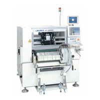
JUKI KE-2080 Operation Manual (43 pages)
High-Speed Chip Shooter, High-Speed Flexible Mounter
Brand:
JUKI
| Category:
Industrial Equipment
| Size: 1.91 MB
Table of Contents
Table of Contents
7
Introduction
8
Overview of this Manual
8
Notational Conventions
8
Organization of this Manual
8
Chapter 1 Overview of the Machine
10
Overview of this Machine
10
Configuration of the Machine
11
Chapter 2 Operation Procedure
12
Flow of PWB Production
12
Overview of Operations
13
Chapter 3 Various Processes During PWB Production
29
When Components Run out (if the Check Box "Stop System When Components Run Out" Is Checked on the "Operation Option" Screen)
29
When Components Run out (if the Check Box "Stop System When Components Run Out" Is Not Checked on the "Operation Option" Screen)
30
When a Mark Recognition Error Occurs
31
When the Laser Sensor Is Stained
32
When an Error (la Recognition Error, Tombstone Error or Irregularly-Shaped Component Error) Occurs
33
When a Vision Recognition Error Occurs
34
When a Nozzle Error Occurs
35
When a Feeder Float Error Is Detected
36
When a Cover Open Error Occurs
37
When the Feeder Bank Moves down (Only if an Overall Feeder Exchange Trolley Option Is Attached on the Machine)
38
Pause for Protection of a Component
39
Continuous PWB Production
40
JUKI KE-2080 Manual (30 pages)
High-Speed Flexible Mounter MS PARAMETER
Brand:
JUKI
| Category:
Industrial Equipment
| Size: 1.06 MB
Table of Contents
Table of Contents
4
Overview
6
Definition
6
Starting up and Exiting the MS Parameter
6
Configuration
9
MS Parameter Storage Locations
10
Basic Operation
19
Control Menu
20
Start up
20
XY Move
21
Z Move
22
Conveyor Control
23
Light Map
23
Light Setting
24
Nozzle up Cylinder
24
Square Adjustment
26
Origin Rough Adjustment
29
XY Axis Correction Coefficient
30
Advertisement
Advertisement
Related Products
JUKI KE-2080R
JUKI KE-2080M
JUKI KE-2070
JUKI KE-2020
JUKI KE-2030
JUKI KE-2040
JUKI KE-2050
JUKI KE-2055R
JUKI KE-2060R
JUKI KE-2070C
JUKI Categories
Sewing Machine
Industrial Equipment
Sewing Machine Accessories
Accessories
Measuring Instruments
More JUKI Manuals
Login
Sign In
OR
Sign in with Facebook
Sign in with Google
Upload manual
Upload from disk
Upload from URL