Table of Contents
Advertisement
UM2435
User manual
®
Bluetooth
Low Energy and 802.15.4 Nucleo pack
based on STM32WB Series microcontrollers
Introduction
The Nucleo pack (P-NUCLEO-WB55) with a Nucleo-68 board and a USB dongle provides
an affordable and flexible way for users to try out new concepts and build prototypes using
STM32WB microcontrollers with a 2.4 GHz radio interface.
This circuit block provides various combinations of performance, power consumption and
®
features. A 2.4 GHz RF transceiver supporting Bluetooth
specification v5.0 and IEEE
802.15.4-2011 PHY and MAC is supported.
Arduino™ Uno V3 connectivity and ST morpho headers allow the user to easily expand the
functionality of the Nucleo open development platform with a wide choice of specialized
shields.
®
The boards are based on a multiprotocol wireless 32-bit microcontroller, based on an Arm
®
®
Cortex
-M4 with FPU, featuring Bluetooth
Low Energy and 802.15.4 radio solution.
The STM32 Nucleo-68 board does not require any separate probe, as it integrates the
ST-LINK/V2-1 debugger/programmer. The board comes with the comprehensive free
STM32 software libraries and examples available with the STM32Cube package.
The USB dongle can be programmed through USB BootLoad or USB DFU. It is also
possible to debug/program it with an external STLink V2 (not delivered), using the SWD
interface.
April 2019
UM2435 Rev 2
1/48
www.st.com
1
Advertisement
Table of Contents

Related Manuals for ST P-NUCLEO-WB55


Summary of Contents for ST P-NUCLEO-WB55
- Page 1 A 2.4 GHz RF transceiver supporting Bluetooth specification v5.0 and IEEE 802.15.4-2011 PHY and MAC is supported. Arduino™ Uno V3 connectivity and ST morpho headers allow the user to easily expand the functionality of the Nucleo open development platform with a wide choice of specialized shields.
-
Page 2: Table Of Contents
Embedded ST-LINK/V2-1 ........25... - Page 3 Arduino™ Uno revision 3 connectors ......37 ST Morpho connectors CN7 and CN10 ......40 Extension connectors CN1 and CN2 on USB dongle .
- Page 4 List of tables UM2435 List of tables Table 1. Ordering information ............9 Table 2.
- Page 5 Nucleo-68 board schematics - ST-Link/V2-1 ........
-
Page 6: Features
– Arduino™ Uno V3 – ST Morpho • Flexible board power supply: ST-LINK/V2-1 USB VBUS and external sources • On-board ST-LINK/V2-1 debugger/programmer with USB re-enumeration capability: mass storage, virtual COM port and debug port • Comprehensive free software libraries and examples available with a variety of examples, as part of the STM32Cube package •... -
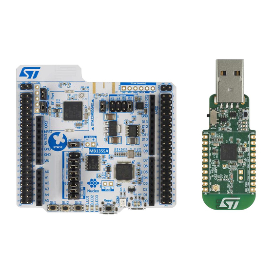
Page 7: Figure 1. Nucleo-68 And Usb Dongle Boards (Top View On The Left, Bottom View On The Right)
UM2435 Features USB dongle • STM32WB microcontroller in UFQFPN48 package ® • 2.4 GHz RF transceiver supporting Bluetooth specification v5.0 and IEEE 802.15.4-2011 PHY and MAC ® ® • Dedicated Arm 32-bit Cortex M0+ CPU for real-time Radio layer • SMPS significantly reduces power consumption in Run mode •... -
Page 8: Product Marking
Any consequences deriving from such usage will not be at ST charge. In no event, ST will be liable for any customer usage of these engineering sample tools as reference design or in production. -
Page 9: Ordering Information
To order the Nucleo-68 board corresponding to the targeted STM32 MCU refer to Table Table 1. Ordering information Order code Target MCU STM32WB55RG (Nucleo-68) P-NUCLEO-WB55 STM32WB55CG (USB dongle) The STM32WB55 codification is explained with an example in Table Table 2. Example of codification STM32WB55RG Description ®... -
Page 10: Hardware Layout And Configuration
The hardware block diagram (see Figure 2) illustrates the connection between the MCU and peripherals (STLINK/V2-1, push buttons, LEDs, Arduino™ UNO V3 connectors and ST-Morpho connectors). Figure 3 Figure 4 help the user to locate these features on the board. -
Page 11: Figure 3. Nucleo-68 Board (Top View)
UM2435 Hardware layout and configuration Figure 3. Nucleo-68 board (top view) UM2435 Rev 2 11/48... -
Page 12: Figure 4. Nucleo-68 Board (Bottom View)
Hardware layout and configuration UM2435 Figure 4. Nucleo-68 board (bottom view) 12/48 UM2435 Rev 2... -
Page 13: Figure 5. Nucleo-68 Board Mechanical Drawing
UM2435 Hardware layout and configuration Figure 5. Nucleo-68 board mechanical drawing UM2435 Rev 2 13/48... -
Page 14: Figure 6. Nucleo-68 Board Schematics
Figure 6. Nucleo-68 board schematics D10A PA10 PA10 PC10 PC10 USB_N PA11 PC11 PC11 USB_P PA12 PC12 PC12 PA13 PA13-JTMS_SWDIO PC13 PC13 SWD reserved PA14 PA14-JTCK_SWCLK PA15 PA15-JTDI SB22 Open Open SB23 PB3-JTDO PB4-NJTRST D10B PB10 PB10 PB11 PB11 PB12 PB12 PB13 PB13... -
Page 15: Figure 7. Nucleo-68 Board Schematics - Rf Part
Figure 7. Nucleo-68 board schematics - RF part JMP4 Meander Antenna 2.4GHz Jumper 2.54mm HEADER_1X2 (see AN3359 on www.st.com) JP4(1-2) Band Pass Filter RF switch Antenna Matching Network LFB182G45CGFD436 100nF LQG15HS2N7S02 LQG15HS2N7S02 FLT1 LQG15HS3N6S02 L5 2.7nH L5 2.7nH VDDRF 3.6nH... -
Page 16: Figure 8. Nucleo-68 Board Schematics - Connectors
Figure 8. Nucleo-68 board schematics - Connectors Morpho connectors HEADER_2X19_M 5V_INT Close HEADER_2X19_M Open CN10 USB_P PB11 Open PA10 Open 5V_EXT USB_N BOOT0 AVDD 5V_USB_MCU Close Open PA13 NRST PB10 PA14 PB12 Open Close Close PC12 PB15 PC13 Open PC14 SB10 PC15 PA15... -
Page 17: Figure 9. Nucleo-68 Board Schematics - Power Management
Figure 9. Nucleo-68 board schematics - Power management Commun Supply Parts 5V_EXT Arduino Morpho LD1117S50TR 5V_INT Vout Open when Board supplied by Li Battery SB24 10uF/25V 100nF/25V Open LD39050PU33R 5V_USB_MCU VOUT SB26 4.7uF/10V HEADER_2X4 HEADER_1X2 Close 5V_USB_STLINK Open SB25 JMP1 JMP2 100nF LED5... -
Page 18: Figure 10. Nucleo-68 Board Schematics - St-Link/V2-1
Figure 10. Nucleo-68 board schematics - ST-Link/V2-1 3V3_STLINK HEADER_1X6 SWD STM32F103 T_VDD Not Fitted 5V_USB_STLINK CN13 100nF CN15 NRST 100nF SWDIO VBUS TXS0108EPW SWCLK VREF TX_STlink (VCP) STLK_TX RX_STlink (VCP) STLK_RX T_SWO 3V3_STLINK Shield SWCLK T_SWCLK SWDIO 1050170001 T_SWDIO NRST... -
Page 19: Usb Dongle
The hardware block diagram in Figure 11 illustrates the connection between the MCU and the peripherals (STLINK/V2-1, push buttons, LEDs, Arduino™ UNO V3 connector and ST-Morpho connectors). Figure 12 Figure 13 help the user locate these features on the board. -
Page 20: Figure 12. Usb Dongle Board (Top View)
Hardware layout and configuration UM2435 Figure 12. USB dongle board (top view) Figure 13. USB dongle board (bottom view) 20/48 UM2435 Rev 2... -
Page 21: Figure 14. Usb Dongle Mechanical Drawing
UM2435 Hardware layout and configuration Figure 14. USB dongle mechanical drawing UM2435 Rev 2 21/48... -
Page 22: Figure 15. Usb Dongle Schematics
Figure 15. USB dongle schematics Close 100nF 100nF PB3-SWO 100nF 5V_USB VDD/VDDT 5V_USB USBLC6-2SC6 LD3985M33R VBUS PA10 PA10 VBAT Close USB_N 5V_USB PA11 100nF USB_P VOUT PA12 VDDUSB SWDIO PA13 PA13-SWDIO SWCLK PA14 PA14-SWCLK 100nF BYPASS PA15 VDDA/VREF+ FCM1608KF-601T03 USB_1 100nF STM32WBxx_QFN48 STM32WBxx_QFN48... -
Page 23: Getting Started
USB driver available on www.st.com/ stm32nucleo before connecting the board. Set correctly the jumper JP1 ([7-8] on USB STL). Plug the Nucleo USB ST-LINK connector (P2P server) and USB dongle (P2P client) to power sources. On the P2P server, you will see a blinking LED for approximately 1 minute. -
Page 24: Table 4. Default Jumper Configuration
= 1.8 V setting is done according to Table Table 4. Default jumper configuration Jumper Definition Default position Comment Power selection ON [7-8] 5 V from ST-LINK measurement current measurement measurement MCU V current measurement RF power Possibility of isolating RF power Level shifter... -
Page 25: Embedded St-Link/V2-1
VIN, E5V and 3.3V on ST Morpho connectors, or VIN and 3.3V on Arduino™ connectors. • It is still possible to use the ST-Link part to program the main MCU using wires between SWD connector and SWD signals available on ST Morpho connectors. 7.4.1 Drivers ®... -
Page 26: St-Link/V2-1 Firmware Upgrade
The ST-LINK/V2-1 embeds a firmware upgrade mechanism for in-situ upgrade through the USB port. As the firmware may evolve during the life time of ST-LINK/V2-1 (for example new functionality, bug fixes, support for new microcontroller families), it is recommended to check for updates on www.st.com... -
Page 27: Power Supply And Selection
This power switch also features a current limitation to protect the PC in case of currents exceeding 750 mA. The Nucleo board and the shield on it can be powered from ST-LINK USB connector CN15, but only ST-LINK circuit has the power before USB enumeration, because the host PC only provides 100 mA to the board at that time. -
Page 28: Figure 18. Jp1[7-8]: 5V_Stl Power Source
Hardware layout and configuration UM2435 and its shield can use up to 500 mA. If the host is unable to provide the requested current, the enumeration fails. Therefore the power switch STMPS2141STR remains OFF and the MCU is not powered. As a consequence LED5 remains turned OFF. In this case it is mandatory to use an external power supply. -
Page 29: Figure 19. Jp1[3-4]: 5V_Vin Power Source
UM2435 Hardware layout and configuration In this configuration JP1[3-4] must be connected as shown in Figure Figure 19. JP1[3-4]: 5V_VIN power source • The board can be also supplied by the USB User (5V_USB_MCU) • No debug is possible on this USB port UM2435 Rev 2 29/48... -
Page 30: Figure 20. Jp1[5-6]: 5V_Usb_Mcu Power Source
Figure 20. JP1[5-6]: 5V_USB_MCU power source Caution: A solder bridge (SB25) can be used (not an ST recommended setting) to bypass the USB PWR protection STMPS2141STR. SB25 can be set only if the board is powered by USB PC and maximum current consumption on 5V_STLINK doesn’t exceed 100 mA (including an extension board or Arduino™... -
Page 31: External Power Supply Output
It is possible to be also in LDO mode by changing the firmware, SB31 needs to be closed. Programing/debugging when the power supply is not from USB ST-LINK (5V_ST_link) VIN or 5V_EXT can be used as external power supply if the current consumption of Nucleo and extensions boards exceeds the allowed current on USB. -
Page 32: Osc Clock Sources
In some cases it can be interesting to use the 3V3 (CN6 pin 4 or CN7 pin 16) directly as power input, for instance when the 3.3 V is provided by an extension board. When Nucleo is powered by 3V3, the ST-LINK is not powered, thus programming and debug features are unavailable. -
Page 33: Reset Sources
Virtual COM port: LPUART/USART LPUART or USART interface of STM32 Microcontroller on the Nucleo-68 board can be connected to STLINK/V2-1 MCU or on Shields on ST-Morpho connectors and Arduino™ UNO V3 connectors. The LPUART/USART selection can be changed by setting related solder bridges. -
Page 34: Leds
• LED6 COM: LED6 is a bi-color LED, whose default status is Red, turns to Green to indicate that communication is in progress between the PC and the ST-LINK/V2-1, as follows: – Slow blinking red / OFF: at power-on, before USB initialization –... -
Page 35: Jumper Configuration
UM2435 Hardware layout and configuration 7.13 Jumper configuration Jumper default position are listed in Table Table 8 summarizes the other settings and configurations. Table 8. Configuration of jumpers and solder bridges Supply source SB24 SB26 SB27 SB28 SB29 (1-2) (3-4) (5-6) (7-8) STlink... -
Page 36: Connectors
• CN1: USB User connector. USB ST-LINK micro-B connector CN15 The USB connector CN15 is used to connect the embedded ST-LINK/V2-1 to the PC for programming and debugging the Nucleo microcontroller. Figure 21. USB STLINK micro-B connector CN15 (front view) -
Page 37: Arduino™ Uno Revision 3 Connectors
UM2435 Connectors Arduino™ Uno revision 3 connectors The Arduino™ connectors CN5, CN6 CN8 and CN9 are female connectors compatible with Arduino™ standard. Most shields designed for Arduino™ fit to the Nucleo board. The Arduino™ connectors on the Nucleo board support the Arduino™ Uno revision 3. Figure 22. -
Page 38: Table 10. Arduino™ Connectors Pinout
Connectors UM2435 The related pinout for Arduino™ connector is detailed in Figure 23 Table Figure 23. Arduino™ connector pinout Table 10. Arduino™ connectors pinout Connector Pin number Pin name Signal STM32 pin Function Reserved for test IOREF IO reference NRST NRST NRST RESET... - Page 39 UM2435 Connectors Table 10. Arduino™ connectors pinout (continued) Connector Pin number Pin name Signal STM32 pin Function ADC1_IN1 ADC1_IN2 ADC1_IN5 ADC1_IN6 ADC1_IN4 ADC1_IN3 SCL/D15 ARD_D15 I2C1_SCL SDA/D14 ARD_D14 I2C1_SDA AVDD VREF+/VDDA VREF+/VDDA SCK/D13 ARD_D13 SPI1_SCK MISO/D12 ARD_D12 SPI1_MISO PWM/MOSI/D11 ARD_D11 TIM1_CH1N/SPI1_MOSI TIM2_CH3 on PB10 PWM/CS/D10...
-
Page 40: St Morpho Connectors Cn7 And Cn10
UM2435 ST Morpho connectors CN7 and CN10 The ST-Morpho connectors CN7 and CN10 are male pin headers accessible on both sides of the board. All signals and power pins of the MCU are available on Morpho connectors. These connectors can also be probed by an oscilloscope, logical analyzer or voltmeter. -
Page 41: Extension Connectors Cn1 And Cn2 On Usb Dongle
UM2435 Connectors Extension connectors CN1 and CN2 on USB dongle The related pinout and the MCU assignment for the extension connectors are detailed in Figure Figure 25. Extension connectors pinout UM2435 Rev 2 41/48... -
Page 42: Appendix A Nucleo-68 And Usb Dongle Mcu Io Assignment
Nucleo-68 and USB dongle MCU IO assignment UM2435 Appendix A Nucleo-68 and USB dongle MCU IO assignment Table 11. IO assignment Nucleo-68 QFN68 USB dongle QFN48 number (MB1355C) (MB1293C) Pin name (function Other Extension Other after reset) Arduino™ Morpho Debug Debug functions connectors... - Page 43 UM2435 Nucleo-68 and USB dongle MCU IO assignment Table 11. IO assignment (continued) Nucleo-68 QFN68 USB dongle QFN48 number (MB1355C) (MB1293C) Pin name (function Other Extension Other after reset) Arduino™ Morpho Debug Debug functions connectors functions CN1-9 CN10-13 (SPI1_MISO) (SPI1_MISO) CN1-10 (SPI1_MOSI, CN10-15A...
- Page 44 Nucleo-68 and USB dongle MCU IO assignment UM2435 Table 11. IO assignment (continued) Nucleo-68 QFN68 USB dongle QFN48 number (MB1355C) (MB1293C) Pin name (function Other Extension Other after reset) Arduino™ Morpho Debug Debug functions connectors functions PA14 CN7-15 SWCLK CN1-4 SWCLK PA15 D5 (PWM)
-
Page 45: Federal Communications Commission (Fcc) And Industry Canada (Ic) Compliance Statements
UM2435Federal Communications Commission (FCC) and Industry Canada (IC) compliance state- Federal Communications Commission (FCC) and Industry Canada (IC) compliance statements FCC compliance statement This device complies with Part 15 of the FCC Rules. Operation is subject to the following two conditions: This device may not cause harmful interference, and This device must accept any interference received, including interference that may cause undesired operation. - Page 46 Federal Communications Commission (FCC) and Industry Canada (IC) compliance statements should be so chosen that the equivalent isotropically radiated power (e.i.r.p.) is not more than that necessary for successful communication. Conformément à la réglementation d'Industrie Canada, le présent émetteur radio peut fonctionner avec une antenne d'un type et d'un gain maximal (ou inférieur) approuvé...
-
Page 47: Revision History
UM2435 Revision history Revision history Table 12. Document revision history Date Revision Changes 28-Sep-2018 Initial release. Added.Section 9: Federal Communications Commission (FCC) and Industry Canada (IC) compliance statements and its subsections. 01-Apr-2019 Minor text edits across the whole document. UM2435 Rev 2 47/48... - Page 48 ST products and/or to this document at any time without notice. Purchasers should obtain the latest relevant information on ST products before placing orders. ST products are sold pursuant to ST’s terms and conditions of sale in place at the time of order acknowledgement.
Need help?
Do you have a question about the P-NUCLEO-WB55 and is the answer not in the manual?
Questions and answers