Table of Contents
Advertisement
Quick Links
Advertisement
Table of Contents

Related Manuals for Cognex In-Sight 3400


Summary of Contents for Cognex In-Sight 3400
- Page 3 The software, this document, nor any copies thereof may be provided to or otherwise made available to anyone other than the licensee. Title to and ownership of this software remains with Cognex Corporation or its licensor. Cognex Corporation assumes no responsibility for the use or reliability of its software on equipment that is not supplied by Cognex Corporation.
- Page 4 Regulations/Compliance Regulations/Compliance Declaration of Conformity Manufacturer Cognex Corporation One Vision Drive Natick, MA 01760 USA Declares this -marked product ® Product Number In-Sight 3400 Complies With 89/336/EEC Electromagnetic Compatibility Directive Compliance Standards EN 55011 Class A EN 61000-3-2 EN 61000-3-3...
- Page 5 Observe these precautions when installing the In-Sight 3400 sensor to reduce the risk of injury or equipment damage: Do not connect the In-Sight 3400 sensor to a power source other than 24VDC. Any other voltage creates a risk of fire or shock and can damage In-Sight components. Always observe the proper polarity.
- Page 6 Precautions...
-
Page 7: Table Of Contents
Connecting the Model 1350 Breakout Module............12 Connecting the Model 1460 I/O Expansion Module ..........13 Connecting the Model 1450 I/O Expansion Module ..........15 Adding the Sensor to a Network Using the In-Sight 3400 GUI ........17 2.5.1 Installing to a DHCP Network ................17 2.5.2... - Page 8 Appendix C ..........................61 Configuring the In-Sight Sensor Using In-Sight PC Host........... 61 C.1.1 Adding the In-Sight 3400 Sensor to a Network ..........61 C.1.2 Logging On to the In-Sight 3400 Sensor ............65 C.1.3 Modifying the In-Sight 3400 Sensor’s Network Settings ....... 66 C.1.4 Configuring the In-Sight Sensor’s I/O Settings..........
- Page 9 ® Installing the In-Sight 3400 Vision Sensor List of Figures Figure 1-1: Standard In-Sight 3400 Components .................2 Figure 1-2: In-Sight 3400 Standalone Configuration ..............4 Figure 1-3: Standalone In-Sight Network with Switch/Router............5 Figure 1-4: In-Sight Network on the Factory Network..............6 Figure 2-1: Control Pad Connection .....................9 Figure 2-2: VGA Connection ......................9...
- Page 10 List of Figures Figure 4-9: Control Pad Dimensions................... 54 Figure A-1: Local Area Connection Properties Dialog ..............55 Figure A-2: Select Network Protocol Dialog ................56 Figure B-1: Accessing the Discrete Output Settings..............57 Figure B-2: Discrete Output Settings Dialog................58 Figure B-3: Accessing the Serial Port Settings................
- Page 11 Vision Sensor List of Tables Table 1-1: In-Sight 3400 Standard Component Descriptions ............3 Table 2-1: In-Sight 3400 Vision Sensor Connections and Indicators ...........8 Table 2-2: IP Address Schemes ....................20 Table 2-3: Subnet Mask Formats....................20 Table 4-1: In-Sight 3400 Sensor, General Specifications............38 Table 4-2: In-Sight 3400 Remote Head Camera, General Specifications ........39...
- Page 12 List of Tables...
-
Page 13: Introduction
The In-Sight 3400 sensor provides an intuitive spreadsheet interface for configuring and monitoring any In-Sight sensor without using a PC. Use the In-Sight 3400 sensor to configure other sensors on a factory network, or remotely from another part of the factory or enterprise network. -
Page 14: In-Sight 3400 Components
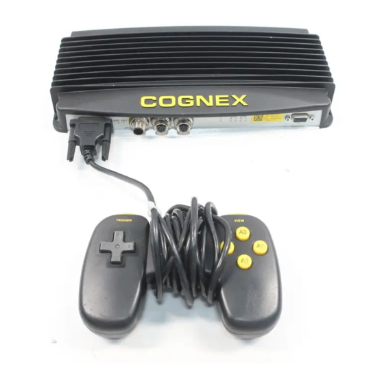
Introduction In-Sight 3400 Components The In-Sight 3400 sensor is shipped with the components shown in Figure 1-1. Component part numbers and descriptions are listed in Table 1-1. Figure 1-1: Standard In-Sight 3400 Components... -
Page 15: In-Sight 3400 Sensor Configurations
84909-xxxx cable number. In-Sight 3400 Sensor Configurations The In-Sight 3400 sensor can operate as a standalone sensor, or as a host sensor on a factory network. For the purposes of the instructions in this manual, a network is an In-Sight 3400 sensor connected over Ethernet to at least one other In-Sight sensor or PC running In-Sight software. -
Page 16: Standalone (No Network) Configuration
The standalone configuration requires a local VGA display to configure applications and monitor the In-Sight 3400 sensor’s runtime operation. In this configuration, the jobs that can be stored are limited to the amount of local storage available on the In-Sight 3400 sensor. A remote serial device must be used for storing image files or for additional job storage. -
Page 17: Figure 1-3: Standalone In-Sight Network With Switch/Router
The standalone In-Sight network shown in Figure 1-3 includes an In-Sight 3400 sensor, two In-Sight 5000 series sensors and a PC running In-Sight Explorer, connected by a switch/router. -
Page 18: Adding An In-Sight Network To A Factory Network
PC workstation with network access. For networks that cover large physical areas, an In-Sight 3400 sensor located on each In-Sight network provides local job configuration and image display for all In-Sight sensors, without a PC. -
Page 19: In-Sight 3400 Installation
Adding the Sensor to a Network Using In-Sight Explorer ....25 Connecting the In-Sight 3400 Vision Sensor This section describes the connection of the In-Sight 3400 to its standard components and optional I/O modules. For a complete list of options and accessories, contact your Cognex sales... -
Page 20: Table 2-1: In-Sight 3400 Vision Sensor Connections And Indicators
PC running In-Sight software. PWR LED This PWR LED indicates the power status of the In-Sight 3400 sensor. The LED is red when the sensor is receiving power during initialization, momentarily switches from green to orange during the LED start-up test, and then switches back to green after initialization is completed. -
Page 21: Connecting The In-Sight 3400 Components
Attach a CS-Mount or C-Mount (with 5mm extension ring) lens to the In-Sight 3400 remote head camera. Installing a lens allows you to see the In-Sight 3400 sensor acquire live video images. The exact lens focal length needed depends on the working distance and the field of... -
Page 22: Figure 2-3: Cam Connection
M12 connector. Attach the male M12 camera cable connector to the In-Sight sensor's CAM connector (Figure 2-3). CAUTION Remove power from the In-Sight 3400 sensor before connecting or disconnecting the remote head camera. “Hot plugging” the remote head camera can damage the In-Sight sensor and/or remote head camera. -
Page 23: Verifying The Standard Connections
Follow these steps to verify that the standard components have been properly connected: Switch on the VGA display. Apply power to the In-Sight 3400 sensor (see section 2.1). The PWR LED is red during initialization, momentarily turns from green to orange during the LED start-up test, and turns green when the sensor is ready for use. -
Page 24: Connecting The Model 1350 Breakout Module
2-pin terminal plug attached to the In-Sight power adapter into the keyed power adapter port on the Breakout Module (Figure 2-5). Restore power to the 24V supply. The green PWR LED on the In-Sight 3400 sensor and the orange +24V LED on the Breakout Module will indicate that the In-Sight 3400 sensor and... -
Page 25: Connecting The Model 1460 I/O Expansion Module
1460 I/O Expansion Module (P/N 800-5815), shown in Figure 2-6, provides convenient access to an In-Sight 3400 sensor's power, serial communications and discrete I/O lines. In addition to the two discrete outputs, acquisition trigger and serial transmit/receive that are standard on In-Sight... -
Page 26: Figure 2-7: Connecting The I/O Cable And Serial Cable
Plug the I/O Module Cable's DB15 male connector into the corresponding female connector on the Expansion Module. Figure 2-7: Connecting the I/O Cable and Serial Cable Plug the M12 connector of the I/O Module Cable into the In-Sight 3400 sensor's 24VDC connector (Figure 2-8). Figure 2-8: Connecting the Expansion Module to In-Sight... -
Page 27: Connecting The Model 1450 I/O Expansion Module
“Camera Power” on the Expansion Module (Figure 2-9). Restore power to the 24V supply. The green PWR LED on the In-Sight 3400 sensor and the +24V LED on the Expansion Module will indicate that the sensor is receiving power. -
Page 28: Figure 2-10: Model 1450 I/O Expansion Module Connections
Expansion Module (Figure 2-10). Restore power to the 24V supply. The green PWR LED on the In-Sight 3400 sensor and the +24V LED on the Expansion Module will indicate that the In-Sight 3400 sensor is receiving... -
Page 29: Adding The Sensor To A Network Using The In-Sight 3400 Gui
Do not connect the 24VDC source to any terminals other than the 2-pin 24VDC power connector. Adding the Sensor to a Network Using the In-Sight 3400 The In-Sight 3400 sensor is ready to be installed as a network host once it has power and is physically connected to the network. NOTE If the Microsoft "Media Sense"... -
Page 30: Installing To A Non-Dhcp Network
In-Sight 3400 Installation 2.5.2 Installing to a Non-DHCP Network To install an In-Sight 3400 sensor on a standalone In-Sight network or factory network without a DHCP server, the sensor’s network settings must be configured manually using the In-Sight Control Pad and a VGA display. -
Page 31: Figure 2-12: Network Dialog
In-Sight Explorer Help file. Use DHCP Server The Use DHCP Server checkbox determines whether the In-Sight 3400 sensor uses DHCP on start up or if the values in the Network dialog will configure TCP/IP. NOTE This box should be checked only if a DHCP server is running on the local network. If a DHCP server does not respond within 60 seconds after startup, the sensor will boot without network support enabled. -
Page 32: Table 2-2: Ip Address Schemes
192.168.0.1 to 192.168.255.254. The default Subnet Mask is 255.255.0.0 Subnet Mask The Subnet Mask defines which part of the In-Sight 3400 sensor’s IP address refers to the network and which part refers to the host. NOTE When DHCP is enabled, this field is grayed out and displays the value assigned by the DHCP server. - Page 33 IP address. Host Name The Host Name assigns a name, or “alias”, for the In-Sight 3400 sensor, as it will appear when browsing the network. Each In-Sight 3400 sensor has its host name set automatically the first time it boots. The format is “is3400_xxxxxx”, where “xxxxxx”...
-
Page 34: Verifying The In-Sight 3400 Sensor Network Connection
In-Sight 3400 Installation An In-Sight 3400 sensor must have a FQDN to be accessible from a remote host that is not part of the local network. The Domain setting sets the string that is appended to the host name to make a FQDN. -
Page 35: Figure 2-13: Logon Dialog
Name does not appear, click the Refresh button. Select a name, and then click OK. A message will appear while the In-Sight 3400 GUI logs on to the In-Sight sensor you selected. The spreadsheet for that sensor will appear. The Host Name of the sensor you are logged on to is displayed in the lower-left corner of the spreadsheet. -
Page 36: Installing The In-Sight Software On A Windows Pc
The In-Sight 3400 sensor may be configured, and its operation monitored over an Ethernet network from a PC. An In-Sight 3400 sensor accessed from a networked PC is configured using mouse and keyboard input. The following must be installed on the PC: ®... -
Page 37: Adding The Sensor To A Network Using In-Sight Explorer
Installing the In-Sight 3400 Vision Sensor Adding the Sensor to a Network Using In-Sight Explorer The In-Sight 3400 sensor is ready to be installed as a network host once it has power and is physically connected to the network. NOTE If the Microsoft "Media Sense"... -
Page 38: Installing To A Non-Dhcp Network
In-Sight 3400 Installation 2.7.2 Installing to a Non-DHCP Network To install an In-Sight 3400 sensor on a network that does not provide a DHCP server, use the In-Sight Connection Manager to configure the In-Sight 3400 sensor's network settings. This installation may also require changes to network settings in Microsoft Windows (see Appendix A, page 55). -
Page 39: Figure 2-15: User Name And Password
® Installing the In-Sight 3400 Vision Sensor You may need to supply administrative credentials (User Name and Password) for at least one In-Sight sensor on your network in order to proceed (Figure 2-15). Click Next. Figure 2-15: User Name and Password... -
Page 40: Figure 2-16: Mac Address
MAC address to the list after they reboot. Click Next. NOTE The MAC address is located on the serial number label affixed to the In-Sight 3400 sensor. This identifier is factory-assigned, unique for every In-Sight sensor and cannot be changed or deleted. -
Page 41: Figure 2-17: Set Network Configuration Dialog
Enter values for the Subnet mask; these settings will be applied to every sensor. The Subnet Mask specifies which parts of the In-Sight 3400 sensor's IP Address are the same for all hosts on the local network and which are unique to each host. See Table 2-3 or consult your network administrator for more information. -
Page 42: Figure 2-18: Enter Ip Address
In-Sight 3400 Installation 10. For each sensor in the table (Figure 2-18), enter a unique IP address in the New IP column. Optionally, you can type in meaningful names for each sensor under the New Name column. 11. Click Next... -
Page 43: Logging On To The In-Sight 3400 Sensor
2.7.3 Logging On to the In-Sight 3400 Sensor After the In-Sight 3400 sensor has been added to the network, log on to the sensor to verify the installation and to configure additional network settings. To log on to a sensor, you must supply a valid User Name and Password. -
Page 44: Modifying The In-Sight 3400 Sensor Network Settings
Default Gateway, DNS Server and Domain name are used, or when moving the In-Sight 3400 sensor from one network to another. Refer to Appendix C for details on changing the In-Sight 3400 sensor’s network settings using In-Sight PC Host. - Page 45 EIP I/O Watchdog Timeout Action: Specifies the In-Sight Ethernet/IP implicit connection timeout behavior. This completes the basic installation procedure for adding an In-Sight 3400 sensor onto a network using In-Sight Explorer. For information on using your In-Sight 3400 sensor, refer to the ® In-Sight...
- Page 46 In-Sight 3400 Installation...
-
Page 47: Using The Control Pad
3 Using the Control Pad In This Section… Direction Buttons ................35 Action Buttons................36 Trigger View Button Button Direction Action Buttons Buttons Figure 3-1: Control Pad Direction Buttons The direction buttons are used in many common operations, including interface navigation, manipulating regions of interest, incrementing/decrementing numeric values and selecting ranges of cells. -
Page 48: Trigger Button
Using the Control Pad 3.1.1 Trigger Button This button manually triggers an image acquisition and updates the spreadsheet. 3.1.2 View Button This button switches the display between the default view and the Custom view of the current spreadsheet. Action Buttons The four action buttons are used to open menus, enter formula data, and manipulate interactive graphics. -
Page 49: Specifications
4 Specifications In This Section… General Specifications ..............37 Detailed I/O Specifications.............40 Dimensional Drawings ..............50 General Specifications The following sections list general specifications for the In-Sight 3400 sensor and remote head camera, and the remote head camera enclosure. -
Page 50: In-Sight 3400 Sensor Specifications
Certifications CE, FCC, UL, CUL. In-Sight 3400 sensors with P/N 800-5809-1 Rev. F and higher have 32MB of non-volatile flash memory. All prior In-Sight 3400 sensors have 16MB of non-volatile flash memory. To locate the Part Number, refer to the Part Number label on the front panel of your sensor. -
Page 51: In-Sight 3400 Remote Head Camera Specifications
® Installing the In-Sight 3400 Vision Sensor 4.1.2 In-Sight 3400 Remote Head Camera Specifications Table 4-2: In-Sight 3400 Remote Head Camera, General Specifications SPECIFICATION DESCRIPTION Image Sensor 1/3-inch CCD Optical 6mm diagonal, 7.4 x 7.4µm sq. pixels. Properties Resolution 640 x 480... -
Page 52: Remote Head Camera Enclosure Specifications
Input pulse should be minimum of 1ms wide. The acquisition trigger input on the In-Sight 3400 sensor is opto-isolated. To trigger from an NPN (pull-down) type photo-detector or PLC output, connect pin 2 (TRG+) to +24V and connect pin 3 (TRG-) to the output of the detector. -
Page 53: High-Speed Outputs
3400 Vision Sensor NOTE When using the In-Sight 3400 sensor with the Breakout Cable, the polarity of the input trigger (pins 2 and 3) is not critical. However, when using the optional Breakout or I/O Expansion Modules, the polarity of the TRG+ and TRG- terminals should be observed. -
Page 54: Figure 4-2: High-Speed Output Connection Example 1
Specifications Example 1 To connect the high-speed outputs to a relay, LED or similar load, connect the negative side of the load to the output and the positive side to +24V. When the output switches on, the negative side of the load is pulled down to 0V, and 24V appears across the load. Use a protection diode for a large inductive load, with the anode connected to the output and the cathode connected to +24V. -
Page 55: Figure 4-4: High-Speed Output Connection Example 3
Use an external NPN to PNP converter when this inversion is not desired. Figure 4-4: High-Speed Output Connection Example 3 The HSOUT status LEDs on the In-Sight 3400 sensor indicate the state of the outputs. The LEDs will illuminate when the outputs are actively pulled low (NPN type output). -
Page 56: Control Pad And Connector Specifications
Specifications 4.2.3 Control Pad and Connector Specifications The In-Sight 3400 sensor can be configured locally using an In-Sight Control Pad connected to the sensor. Table 4-6 provides pin numbers and assignments for the CONTROL PAD port. Table 4-6: Control Pad Port Pin Numbers and Assignments... -
Page 57: 24Vdc Breakout Connector And Cable Specifications
® Installing the In-Sight 3400 Vision Sensor 4.2.4 24VDC Breakout Connector and Cable Specifications The 24VDC Breakout connector provides access to power, serial communications, trigger and high-speed outputs. The Breakout cable is not terminated (Table 4-7). Table 4-7: 24VDC Breakout Connector Cable Pin-Out PIN# SIGNAL NAME WIRE COLOR... -
Page 58: I/O Module Cable
I/O Expansion Module and the optional 1450 I/O Expansion Module. The I/O Module cable connects the In-Sight 3400 sensor directly to the applicable I/O Expansion module via the DB15 connector. When the 1350 Breakout Module, 1460 I/O Expansion Module or 1450 I/O Expansion Module is used, all power and communication lines used by the In-Sight 3400 sensor are connected via the I/O Module cable. -
Page 59: Network Cable Specifications
3400 Vision Sensor 4.2.6 Network Cable Specifications The Network cable is used to connect the In-Sight 3400 sensor to other network sensors. The Network cable provides network connections to multiple sensors via a network switch or router, or a single sensor using the Crossover Coupler. -
Page 60: Camera Cable Specifications
Specifications 4.2.7 Camera Cable Specifications The Camera cable connects the In-Sight 3400 remote head camera to the sensor. The Camera cable provides power and communications to the camera. Table 4-10: Camera Cable Pin-Out P1 PIN# SIGNAL NAME P2 PIN# CTRL+... -
Page 61: Vga Connector Specifications
Installing the In-Sight 3400 Vision Sensor 4.2.8 VGA Connector Specifications The VGA connector located on the In-Sight 3400 sensor is a standard, analog VGA, DB15 connector. This connection may be used to connect any standard VGA monitor. Table 4-11: VGA Connector Pin-Out... -
Page 62: Dimensional Drawings
Dimensional Drawings Dimensional drawings for the In-Sight 3400 sensor components are provided in the following sections: 4.3.1 Sensor Dimensions The In-Sight 3400 sensor dimensions are illustrated in Figure 4-5. Dimensions are in millimeters (inches). Figure 4-5: In-Sight 3400 Sensor Dimensions... -
Page 63: Remote Head Camera Dimensions
® Installing the In-Sight 3400 Vision Sensor 4.3.2 Remote Head Camera Dimensions The In-Sight 3400 remote head camera dimensions are illustrated in Figure 4-6. Dimensions are in millimeters (inches). Figure 4-6: Remote Head Camera Dimensions... -
Page 64: Remote Head Camera Enclosure Dimensions
Specifications 4.3.3 Remote Head Camera Enclosure Dimensions The remote head camera enclosure dimensions are illustrated in Figure 4-7. Dimensions are in millimeters (inches). Figure 4-7: Remote Head Camera Enclosure Dimensions... -
Page 65: Remote Head Camera Mount Dimensions
® Installing the In-Sight 3400 Vision Sensor 4.3.4 Remote Head Camera Mount Dimensions The remote head camera mounting bracket dimensions are illustrated in Figure 4-8. Dimensions are in millimeters (inches). Refer to Appendix D for installation instructions. Figure 4-8: Remote Head Camera Mount Dimensions... -
Page 66: Control Pad Dimensions
Specifications 4.3.5 Control Pad Dimensions The In-Sight Control Pad dimensions are illustrated in Figure 4-9. Dimensions are in millimeters (inches). Figure 4-9: Control Pad Dimensions... -
Page 67: Configuring Microsoft Windows Network Settings
This section provides information on how to configure Microsoft Windows network settings in order to connect to an In-Sight 3400 sensor running In-Sight Explorer on a non-DHCP network. The steps listed below and the example dialogs are specific to Windows XP Professional. -
Page 68: Figure A-2: Select Network Protocol Dialog
Configuring Microsoft Windows Network Settings Click the “Use the following IP address” radio button (Figure A-2). The IP address, Subnet Mask, Default Gateway, Preferred DNS server and Alternate DNS server fields, which are grayed-out, become active. Figure A-2: Select Network Protocol Dialog Enter an appropriate IP address. -
Page 69: Configuring The In-Sight Sensor's I/O Settings Using In-Sight Explorer
Appendix B B.1 Configuring the In-Sight Sensor’s I/O Settings Using In-Sight Explorer Before an I/O Expansion Module can be used, the In-Sight sensor’s settings must be configured to recognize the availability of the additional inputs and outputs, as well as the added serial hardware handshaking capability. -
Page 70: Figure B-2: Discrete Output Settings Dialog
Configuring the In-Sight Sensor’s I/O Settings Using In-Sight Explorer Open the Output Module drop-down list at the bottom left of the window (Figure B-2) and select I/O Expansion Module. The Discrete Output window will automatically reconfigure to correspond to the I/O Expansion Module. Configure the Line Name, Type and Details as required. -
Page 71: Enabling Hardware Handshaking
® Installing the In-Sight 3400 Vision Sensor The sensor can also be configured to use the I/O Expansion Module by opening the Discrete Input dialog and following steps 4 - 6, as described above. Once the I/O Expansion Module is selected in either the Discrete Input or Discrete Output dialogs, it is automatically enabled for both inputs and outputs, and hardware handshaking may be used in serial communications. -
Page 72: Figure B-4: Serial Port Settings Dialog
Configuring the In-Sight Sensor’s I/O Settings Using In-Sight Explorer Select Hardware from the Handshake drop-down list (Figure B-4). Figure B-4: Serial Port Settings Dialog ® Refer to the In-Sight Explorer Help file for details on using the Discrete and Serial Input/Output functions in the In-Sight spreadsheet. -
Page 73: Configuring The In-Sight Sensor Using In-Sight Pc Host
C.1 Configuring the In-Sight Sensor Using In-Sight PC Host C.1.1 Adding the In-Sight 3400 Sensor to a Network The In-Sight 3400 sensor is ready to be installed as a network host once it has power and is physically connected to the network. NOTE If the Microsoft "Media Sense"... -
Page 74: Figure C-1: System Menu
Configuring the In-Sight Sensor Using In-Sight PC Host Installing to a Non-DHCP Network To install an In-Sight 3400 sensor on a network that does not provide a DHCP server, use another In-Sight 3400 sensor or In-Sight PC Host to manually configure the In-Sight 3400 sensor's network settings. -
Page 75: Figure C-2: Logon Dialog
Do not delete or change the first six characters that are already entered. NOTE The MAC address is located on the serial number label affixed to the In-Sight 3400 sensor. This identifier is factory-assigned, unique for every In-Sight sensor, and cannot be changed or deleted. -
Page 76: Figure C-4: Ip Configuration Message Box
10. Enter a Subnet Mask for the local network. The Subnet Mask specifies which parts of the In-Sight 3400 sensor's IP address are the same for all hosts on the local network, and which are unique to each host. See Table 2-3 or consult your network administrator for more information. -
Page 77: Logging On To The In-Sight 3400 Sensor
C.1.2 Logging On to the In-Sight 3400 Sensor After the In-Sight 3400 sensor has been added to the network, log on to the sensor to verify the installation and to configure additional network settings. To log on to a sensor, you must supply a valid User Name and Password. -
Page 78: Modifying The In-Sight 3400 Sensor's Network Settings
C.1.3 Modifying the In-Sight 3400 Sensor’s Network Settings You may need to change the In-Sight 3400 sensor’s network settings when installing it to a non- DHCP network where a Default Gateway, DNS Server, and Domain name are used, or when moving the In-Sight 3400 sensor from one network to another. -
Page 79: Figure C-8: System Menu
® Installing the In-Sight 3400 Vision Sensor From the In-Sight spreadsheet, open the System menu (Figure C-8). Figure C-8: System Menu Select Settings to open the Settings menu (Figure C-9). Figure C-9: Settings Menu... -
Page 80: Figure C-10: Network Dialog
IP address-numbering scheme of the local network. Subnet Mask: Specifies which parts of the In-Sight 3400 sensor's IP address are the same for all hosts on the local network, and which are unique to each host. -
Page 81: Configuring The In-Sight Sensor's I/O Settings
® Installing the In-Sight 3400 Vision Sensor C.1.4 Configuring the In-Sight Sensor’s I/O Settings Before an I/O Expansion Module can be used, the In-Sight sensor's settings must be configured to recognize the availability of the additional inputs and outputs, as well as the added serial hardware handshake capability. -
Page 82: Figure C-12: Settings Menu
Configuring the In-Sight Sensor Using In-Sight PC Host Select Settings to open the Settings menu (Figure C-12). Figure C-12: Settings Menu Select Discrete Output to open the Discrete Output dialog (Figure C-13). Figure C-13: Discrete Output Dialog, Default Settings... -
Page 83: Figure C-14: Discrete Output Dialog, I/O Expansion Configuration
® Installing the In-Sight 3400 Vision Sensor Open the drop-down list to the left of the OK button and select I/O Expansion Module. The Discrete Output dialog will automatically reconfigure to correspond to the I/O Expansion Module, as shown in Figure C-14. Configure the Line Name, Type and Details as required. -
Page 84: Figure C-15: System Menu
Configuring the In-Sight Sensor Using In-Sight PC Host Once the I/O Expansion Module is selected in either the Discrete Input or Discrete Output dialogs, it is automatically enabled for both inputs and outputs, and hardware handshaking may be used in serial communications. Enabling Hardware Handshaking Open the In-Sight PC Host program and log on to the sensor. -
Page 85: Figure C-16: Settings Menu
® Installing the In-Sight 3400 Vision Sensor Select Settings to open the Settings menu (Figure C-16). Figure C-16: Settings Menu Select Serial Port 1 to open the Serial Port 1 dialog (Figure C-17). Figure C-17: Serial Port Dialog... -
Page 86: Figure C-18: Serial Port Dialog, Hardware Handshaking Enabled
Configuring the In-Sight Sensor Using In-Sight PC Host Select Hardware from the Handshake drop-down list (Figure C-18). Figure C-18: Serial Port Dialog, Hardware Handshaking Enabled... -
Page 87: Installing The Remote Head Camera Mount
Appendix D D.1 Installing the Remote Head Camera Mount The remote head camera mount kit includes the hardware required to secure the remote head camera to a mounting surface. The Lens Tube (item 6) is included with the kit, but is not required for all applications. - Page 88 Installing the Remote Head Camera Mount...
-
Page 89: System Recovery Using Safe Mode
Appendix E System Recovery Using Safe Mode When power is first applied to the In-Sight 3400 sensor, the PWR LED will be red while the sensor initializes. When initialization is complete, the LED will momentarily change from green to orange during the LED start-up test, and then switch back to green. However, initialization failure may be caused by corrupted job files, settings, or incorrect configurations. - Page 90 Installing the In-Sight ® 3400 Vision Sensor www.cognex.com P/N 597-0025-02...
Need help?
Do you have a question about the In-Sight 3400 and is the answer not in the manual?
Questions and answers