
Related Manuals for Toro Groundsmaster 3500 30807


Summary of Contents for Toro Groundsmaster 3500 30807
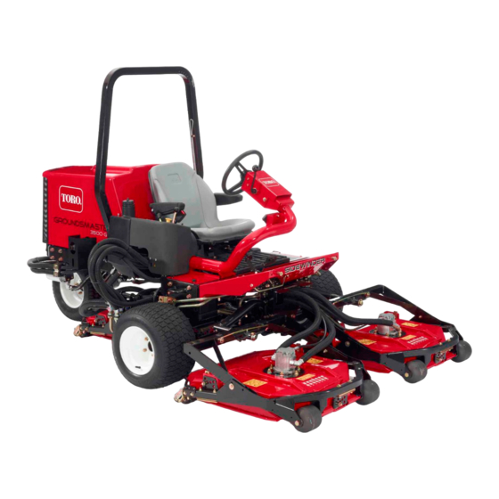
- Page 1 Form No. 14209SL Rev C ® Groundsmaster 3500 (Models 30807 and 30809) Original Instructions (EN)
- Page 2 THE TORO COMPANY 2019 This document and all information contained herein is the sole property of The Toro Company (and/or its affiliated companies). No intellectual property rights are granted by the delivery of this document or the disclosure of its content. This document shall not be...
- Page 3 Reader Comments The Toro Company Technical Assistance Center maintains a continuous effort to improve the quality and usefulness of its publications. To do this effectively, we encourage user feedback. Please comment on the completeness, accuracy, organization, usability, and readability of this manual by an e-mail to servicemanuals@toro.com...
- Page 4 NOTES...
- Page 5 Chapter 2 of this service manual. Additional copies of the Operator’s Manual and Parts Catalog are available on the internet at www.Toro.com. The Toro Company reserves the right to change product specifications or this publication without notice. The Toro Company - 2014, 2018, 2019...
- Page 6 This page is intentionally blank. Groundsmaster 3500...
-
Page 7: Table Of Contents
Table Of Contents Chapter 1 - Safety Chapter 6 - Electrical System General Safety Instructions ....1 - 1 General Information ......6 - 2 Jacking Instructions . - Page 8 This page is intentionally blank. Groundsmaster 3500...
-
Page 9: General Safety Instructions
General Safety Instructions The GROUNDSMASTER 3500 was tested and certified sult in injury. To reduce the potential for any injury, by TORO for compliance with existing standards and comply with the following safety instructions. specifications as identified in the Operator’s Manual. Al-... - Page 10 While Operating 1. Always wear your seat belt. 10.When starting the engine: 2. Do not run the engine in a confined area without ade- A. Engage parking brake. quate ventilation. Exhaust fumes are hazardous and B. Be sure traction pedal is in neutral and blade drive could be deadly.
- Page 11 The Toro Company. 6. Before disconnecting or performing any work on the hydraulic system, all pressure in system must be re- lieved by stopping engine and lowering cutting units to the ground.
-
Page 12: Jacking Instructions
Jacking Instructions CAUTION When changing attachments, tires, or performing other service, use correct blocks, hoists, and jacks. Make sure machine is parked on a solid lev- el floor such as a concrete floor. Prior to raising machine, remove any attachments that may inter- fere with the safe and proper raising of the ma- chine. -
Page 13: Safety And Instruction Decals
Numerous safety and instruction decals are affixed to the Groundsmaster 3500. If any decal becomes illegible or damaged, install a new decal. Part numbers for re- placement decals are listed in your Parts Catalog. Order replacement decals from your Authorized Toro Distribu- tor. Groundsmaster 3500 Safety... - Page 14 This page is intentionally blank. Safety Page 1 - 6 Groundsmaster 3500...
-
Page 15: Product Records
Chapter 2 Product Records and Maintenance Table of Contents PRODUCT RECORDS ......MAINTENANCE ......EQUIVALENTS AND CONVERSIONS . -
Page 16: Equivalents And Conversions
Equivalents and Conversions 0.09375 Groundsmaster 3500 Product Records and Maintenance Page 2 − 2... -
Page 17: Torque Specifications
For critical applications, as determined reduced by 25% for lubricated fasteners to achieve by Toro, either the recommended torque or a torque that the similar stress as a dry fastener. Torque values may is unique to the application is clearly identified and spe- also have to be reduced when the fastener is threaded cified in this Service Manual. - Page 18 Standard Torque for Dry, Zinc Plated, and Steel Fasteners (Inch Series) Grade 1, 5, & SAE Grade 1 Bolts, Screws, Studs, & SAE Grade 5 Bolts, Screws, Studs, & SAE Grade 8 Bolts, Screws, Studs, & Thread Size 8 with Thin Sems with Regular Height Nuts Sems with Regular Height Nuts Sems with Regular Height Nuts...
- Page 19 Standard Torque for Dry, Zinc Plated, and Steel Fasteners (Metric Fasteners) Class 8.8 Bolts, Screws, and Studs with Class 10.9 Bolts, Screws, and Studs with Thread Size Regular Height Nuts Regular Height Nuts (Class 8 or Stronger Nuts) (Class 10 or Stronger Nuts) M5 X 0.8 57 + 5 in−lb 640 + 60 N−cm...
-
Page 20: Specifications
Other Torque Specifications SAE Grade 8 Steel Set Screws Wheel Bolts and Lug Nuts Recommended Torque Thread Size Recommended Torque* Thread Size Square Head Hex Socket 7/16 − 20 UNF 65 + 10 ft−lb 88 + 14 N−m Grade 5 1/4 −... -
Page 21: Introduction
Chapter 3 Kubota Diesel Engine Model 30807 Table of Contents SPECIFICATIONS ......Fuel Tank Removal . - Page 22 This page is intentionally left blank. Kubota Diesel Engine Groundsmaster 3500−D Page 3 − 2...
-
Page 23: Specifications
Specifications Item Description Make / Designation Kubota D1105- E3B or D1105- E4B, 4- Stroke, Liquid Cooled, OHV Diesel Number of Cylinders Bore in. (mm) 3.07 (78.0) Stroke in. (mm.) 3.09 (78.4) Total Displacement cu. In. (cc) 68.53 (1123) Firing Order 1 (fan end) - 2 - 3 (flywheel end) Combustion Chamber Spherical Type... -
Page 24: Introduction
Service and repair parts for Kubota gasoline engines maintenance, troubleshooting, testing, and repair of the are supplied through your local Toro Distributor. If a diesel engine used in the Groundsmaster 3500- D parts list is not available, be sure to provide your distribu- (Model 30807). - Page 25 This page is intentionally left blank. Groundsmaster 3500−D Page 3 − 5 Kubota Diesel Engine...
-
Page 26: Air Cleaner And Muffler
Service and Repairs Air Cleaner and Muffler Figure 2 1. Exhaust guard 8. Lock washer 15. Burp (Actuator) valve 2. Cap screw 9. Exhaust gasket 16. Mounting band assembly 3. Muffler 10. Hose clamp 17. Shoulder bolt 4. Flange head screw 11. -
Page 27: Check Air Filter, Dust Cup, & Burp Valve
Check Air Filter, Dust Cup, & Burp Valve The air cleaner body, air filter, dust cup, and burp valve should be checked daily, prior to operation. IMPORTANT: Any leaks in the air cleaner system will cause serious engine damage. Make sure that all air cleaner components are in good condition and are properly secured during operation. -
Page 28: Fuel System
Fuel System 11 8 7 16 Thread Sealant Thread Sealant Thread Sealant Figure 5 1. Cap screw 16. Fuel hose − tank 30. R−clamp 2. Fuel tank 31. Tank support 17. Fuel hose − stand pipe 3. Cap screw 32. Fuel pump 18. -
Page 29: Fuel Tank Removal
Fuel Tank Installation (Fig. 5) DANGER 1. Position fuel tank to the machine. 2. Connect both fuel hoses to the tank and secure with Because diesel fuel is highly flammable, use cau- tion when storing or handling it. Do not smoke hose clamps. -
Page 30: Radiator
Radiator − Radiator/Hydraulic Fluid Cooler Traction Units Prior to Serial No 314000001 24 25 Figure 7 1. Drain−cock valve 14. Reservoir bracket 27. Hydraulic tube 2. Flange head screw 15. Wire form latch 28. Hydraulic fluid cooler hose 3. Flange nut 16. - Page 31 Traction Units Serial No 314000001 & Up RIGHT FRONT Figure 8 1. Expansion tank 12. Radiator 23. Hydraulic hose 2. Hose clamp 13. Straight fitting 24. Lower radiator hose 3. Coolant hose 14. Drain−cock 25. Hose clamp 4. Flange head screw 15.
-
Page 32: Removal
Removal Units prior to serial no. 314000001 use a separate hy- draulic oil cooler. The hydraulic oil cooler on later units is combined with the radiator assembly. It is not neces- sary to drain the hydraulic system when removing the radiator on early units prior to serial no. - Page 33 7. Connect following hoses to the radiator or radiator/oil 9. Make sure drain- cock valve is closed. Fill radiator cooler assembly: with coolant to the bottom of the filler neck. A. Upper radiator hose to the water pump. 10.Install engine hood to the machine. Close and latch hood.
-
Page 34: Diesel Engine
Diesel Engine Thread Sealant Figure 10 1. Engine mount bracket − RH 17. Engine ground 33. Lock washer 2. Cap screw 18. Flat washer 34. Flange nut 3. Hardened washer 19. Cap screw 35. Engine mount bracket − front 4. Engine mount 20. -
Page 35: Removal
Removal 1. Park machine on a level surface, lower cutting units, stop engine, engage parking brake, and remove key from the ignition switch. 2. Open and remove engine hood from the machine. Slide seat all the way forward. 3. Disconnect both battery cables at the battery (see Battery Service in Chapter 6 −... - Page 36 RIGHT FRONT Figure 15 1. Engine mount bracket 5. Hardened washer 8. Hardened washer 2. Flange nut 6. 10 mm cap screw (4) 9. Long spacer (4) 3. Flange screw 7. 8 mm cap screw (1) 10. Short spacer (1) 4.
-
Page 37: Installation
15.Separate hydrostat and pump assembly from the en- tion in Chapter 5− Hydraulic System). gine as follows (Fig. 15): 8. Connect fuel hose to the fuel pump (Fig. 11) and front A. Remove traction belt from the engine flywheel injector nozzle. and hydrostat pulleys. - Page 38 This page is intentionally left blank. Kubota Diesel Engine Groundsmaster 3500−D Page 3 − 18...
- Page 39 Chapter 4 Kubota Gasoline Engine Model 30809 Table of Contents SPECIFICATIONS ......Fuel Evaporative Control System INTRODUCTION .
- Page 40 This page is intentionally left blank. Kubota Gasoline Engine Groundsmaster 3500−G Page 4 − 2...
-
Page 41: Specifications
Specifications Item Description Make / Designation Kubota, Vertical, 4−Cycle, 3 Cylinder, Liquid Cooled, Gasoline Engine Bore in. (mm) 2.93 (74.5) Stroke in. (mm) 2.90 (73.6) Total Displacement cu. In. (cc) 58.68 (962) Compression Ratio 9.2:1 Ignition Timing 31_ BTDC @ 3600 rpm Ignition System Full Transistor Battery Ignition Type Firing Order... -
Page 42: Introduction
Service and repair parts for Kubota gasoline engines maintenance, troubleshooting, testing, and repair of the are supplied through your local Toro Distributor. If a gasoline engine used in the Groundsmaster 3500−G parts list is not available, be sure to provide your distribu- (Model 30809). - Page 43 KGST software and Ecom interface driver to the dia- gnostic connector above the engine ECU (Fig. 3). Con- Figure 2 tact your Toro distributor for assistance in Kubota engine 1. Engine (Model 30809) troubleshooting, or to acquire Kubota engine software 2.
-
Page 44: Service And Repairs
Service and Repairs Air Cleaner and Muffler 22 − 28 ft−lbs (30 − 38 N−m) 22 − 28 ft−lbs (30 − 38 N−m) 30 to 44 ft−lb (41 to 59 N−m) Figure 4 1. Muffler flange cover 11. Exhaust gasket 20. -
Page 45: Check Air Filter, Dust Cup, & Burp Valve
Check Air Filter, Dust Cup, & Burp Valve take place. These chemical reactions reduce the amount of CO, HC and NO in the exhaust. Two (2) oxy- The air cleaner body, air filter, dust cup, and burp valve gen sensors are included in the exhaust system and are should be checked daily, prior to operation. -
Page 46: Fuel System
Fuel System 175 to 200 in−lb (20 to 22 N−m) RIGHT FRONT 17 18 Figure 6 1. Fuel tank 10. Seat support strap 19. Cap screw 2. Hose clamp 11. Pump gasket 20. Strap 3. Fuel hose − crossover 12. Fuel pump 21. -
Page 47: Fuel Tank Removal
Clean Fuel Tank DANGER Clean the fuel tank every 2 years. Also, clean the fuel tank if the fuel system becomes contaminated or if the Because gasoline is highly flammable, use cau- machine is to be stored for an extended period. tion when storing or handling it. -
Page 48: Fuel Evaporative Control System
Fuel Evaporative Control System (Unit Serial No. Prior to 315000001) RIGHT 11 1 FRONT Thread Sealant Figure 7 1. Hose clamp 8. Fuel hose 14. Fuel hose 2. Fuel hose 9. Anchor clamp 15. Fuel hose 3. Elbow fitting 10. Vent tube 16. -
Page 49: Carbon Canister Removal
Carbon Canister Removal 1. Park machine on a level surface, lower cutting units, stop engine, engage parking brake and remove key from the ignition switch. 2. Raise and support hood. DANGER Gasoline is flammable. Use caution when storing or handling it. Do not smoke while filling the fuel tank. -
Page 50: Radiator/Hydraulic Fluid Cooler
Radiator/Hydraulic Fluid Cooler RIGHT FRONT Figure 10 1. Expansion tank 12. Radiator 23. Hydraulic hose 2. Hose clamp 13. Straight fitting 24. Lower radiator hose 3. Coolant hose 14. Drain−cock 25. Hose clamp 4. Flange head screw 15. Lower radiator shield 26. -
Page 51: Radiator Removal
Radiator Removal 1. Park machine on a level surface, lower cutting units, stop engine, engage parking brake, and remove key from the ignition switch. 2. Open and remove engine hood from the machine. CAUTION Do not open radiator cap or drain coolant if the radiator or engine is hot. - Page 52 9. Prime the hydraulic pumps (see Prime the Hydraulic Pumps in Chapter 5− Hydraulic System in this manual). 10.Start the unit and run engine to normal operating temperature. Use all of the hydraulic controls while the engine is running to distribute the hydraulic fluid throughout the system.
- Page 53 This page is intentionally left blank. Groundsmaster 3500−G Page 4 − 15 Kubota Gasoline Engine...
-
Page 54: Engine
Engine RIGHT FRONT Figure 12 1. Pump mount plate 13. Exhaust gasket 25. Cap screw 2. Mount bracket − front 14. Flange head screw 26. Flat washer 3. Cap screw 15. Hardened washer 27. Engine ground 4. Wire harness bracket 16. -
Page 55: Engine Removal
Engine Removal 1. Park machine on a level surface, lower cutting units, stop engine, engage parking brake, and remove key from the ignition switch. 2. Open and remove engine hood from the machine. Slide seat all the way forward. 3. Disconnect air hose from the air cleaner and radiator. - Page 56 RIGHT FRONT Figure 14 1. Engine mount bracket 5. Hardened washer 8. Hardened washer 2. Flange nut 6. 10 mm cap screw (4) 9. Long spacer (4) 3. Flange screw 7. 8 mm cap screw (1) 10. Short spacer (1) 4.
-
Page 57: Engine Installation
IMPORTANT: Make sure not to damage the engine, tion in Chapter 5− Hydraulic System in this manual). fuel and hydraulic lines, electrical harness, or other 7. Connect fuel hoses from the fuel pump and carbon parts while removing the engine. canister to engine. - Page 58 19.Prime the hydraulic pumps (see Prime the Hydraulic Pumps in Chapter 5− Hydraulic System in this manual). 20.Start the unit and run engine to normal operating temperature. Use all of the hydraulic controls while the engine is running to distribute the hydraulic fluid throughout the system.
- Page 59 Chapter 5 Hydraulic System Table of Contents SPECIFICATIONS ......Blade Braking Relief Valve (RV) Adjustment GENERAL INFORMATION .
-
Page 60: Specifications
Specifications Item Description Piston Pump (Hydrostat) Variable displacement piston pump Charge Relief Pressure 100 to 150 PSI (6.9 to 10 Bar) Traction Circuit Relief Pressure (Forward Only) 3500 PSI (241.3 Bar) Maximum Displacement 1.44 cu. in./rev (23.6 cc/rev) Gear Pump 2 stage fixed displacement gear type pump Displacement Section 1 (P1) 0.95 cu. -
Page 61: General Information
Traction Circuit Component Failure The Groundsmaster 3500 traction circuit is a closed Once the Toro high flow hydraulic filter kit has been loop system that includes the hydrostat and three (3) placed in the circuit, raise and support the machine with wheel motors. -
Page 62: Hydraulic Hoses
For additional hydraulic hose information, refer to Toro Service Training Book, Hydraulic Hose Servicing (Part Number 94813SL). -
Page 63: Hydraulic Hose And Tube Installation (O−Ring Face Seal Fitting)
Hydraulic Hose and Tube Installation (O−Ring Face Seal Fitting) 1. Make sure threads and sealing surfaces of the hose/ C. Use a second wrench to tighten the nut to the cor- tube and the fitting are free of burrs, nicks, scratches or rect Flats From Wrench Resistance (F.F.W.R.). -
Page 64: Hydraulic Fitting Installation (Sae Straight Thread O−Ring Fitting Into Component Port)
Hydraulic Fitting Installation (SAE Straight Thread O−Ring Fitting into Component Port) Non−Adjustable Fitting (Fig. 4) 5. If a torque wrench is not available, or if space at the port prevents use of a torque wrench, an alternate meth- 1. Make sure all threads and sealing surfaces of fitting od of assembly is the Flats From Finger Tight (F.F.F.T.) and component port are free of burrs, nicks, scratches method. - Page 65 Adjustable Fitting (Fig. 6) 1. Make sure all threads and sealing surfaces of fitting and component port are free of burrs, nicks, scratches or any foreign material. 2. As a preventative measure against leakage, it is rec- ommended that the O−ring be replaced any time the connection is opened.
-
Page 66: Special Tools
Contains one each: 1000 PSI (70 Bar), 5000 PSI (350 Bar) and 10000 PSI (700 Bar) gauges. Use gauges as recommended in Testing section of this chapter. Toro Part Number: TOR47009 Figure 8 15 GPM Hydraulic Tester (Pressure and Flow) This tester requires O−ring Face Seal (ORFS) adapter... - Page 67 3. FLOW METER: This meter measures actual fluid flow in the operating circuit with a gauge rated from 4 to 40 GPM (20 to 150 LPM). Toro Part Number: AT40002 Figure 10 NOTE: This tester does not include hoses (see Hydrau- lic Hose Kit TOR6007 below).
- Page 68 Toro Part Number: TOR6011 NOTE: This kit does not include hoses (see Hydraulic Hose Kit TOR6007 above). NOTE: Replacement filter element is Toro part number TOR6012. Filter element cannister tightening torque is 25 ft−lb (34 N−m). O−Ring Kit The O−ring kit includes O−rings in a variety of sizes for face seal and port seal hydraulic connections.
- Page 69 This kit includes a variety of O−ring Face Seal fittings to enable you to connect test gauges into the system. The kit includes: tee’s, unions, reducers, plugs, caps and male test fittings. Toro Part Number: TOR4079 Figure 14 Measuring Container Use this container for doing hydraulic motor efficiency testing (motors with case drain lines only).
- Page 70 Figure 17 A remote stater switch can also be constructed using Toro switch #106−2027, a length of 14 gauge wire, a 20 amp in−line fuse, two (2) alligator clips and necessary MACHINE connectors. Connecting the wire to switch terminals 1...
- Page 71 Wheel Hub Puller Toro Part Number: TOR4097 The wheel hub puller allows safe removal of the wheel hub from the shaft of wheel motors. Figure 20 Groundsmaster 3500 Page 5 − 13 Hydraulic System...
-
Page 72: Hydraulic Schematics
Hydraulic Schematics Hydraulic System Page 5 − 14 Groundsmaster 3500... - Page 73 Groundsmaster 3500 Page 5 − 15 Hydraulic System...
-
Page 74: Hydraulic Flow Diagrams
Hydraulic Flow Diagrams Hydraulic System Page 5 − 16 Groundsmaster 3500... -
Page 75: Traction Circuit
Traction Circuit The traction circuit of the hydraulic system consists of a wheel motor flows to the front wheel motors, turning hydrostat connected in a closed loop circuit to three or- them in the reverse direction. Fluid flow out of the front bital geroller wheel motors. - Page 76 Hydraulic System Page 5 − 18 Groundsmaster 3500...
- Page 77 Groundsmaster 3500 Page 5 − 19 Hydraulic System...
-
Page 78: Cutting Unit Circuit
Cutting Unit Circuit Cutting Unit Blade Braking (Units Prior to Serial No. 314000001) The gear pump (P1) is directly coupled to the the hydros- tat which is driven by the engine. Taking its suction di- When the solenoid valve (S1) is de−energized, the rectly from the hydraulic tank, the gear pump (P1) blade relief cartridge (BV) shifts to its closed position, supplies fluid flow to the manifold block and to the cutting... - Page 79 Cutting Unit Blade Braking (Unit Serial No. TO DECK FROM DECK 314000001 & Up) MOTORS MOTORS When the solenoid valve (S) is de−energized, the flow to the cutting deck motors and the relief valve (RV) is re- ORIFICE moved allowing relief valve (RV) to shift. The shifted re- lief valve removes flow from the orifice at the logic cartridge (LC2), causing a balanced pressure condition which shifts the logic cartridge, blocking the return oil...
- Page 80 Hydraulic System Page 5 - 22 Groundsmaster 3500...
-
Page 81: Lift Circuit (Up)
Lift Circuit (Up) Raise Cutting Units When the cutting units are to be raised, the 2- spool valve is positioned by moving the cutting unit shift lever The gear pump (P2) is directly coupled to the hydrostat to RAISE. Flow is directed to cap ends of the lift cylin- through gear pump (P1) and driven by the engine. - Page 82 Hydraulic System Page 5 - 24 Groundsmaster 3500...
-
Page 83: Lift Circuit (Down) & Counterbalance
Lift Circuit (Down) & Counterbalance Lower Cutting Units to LOWER. Pressure from gear pump (P2) is used to shift the pilot valve in the 2- spool valve. This shifting of The gear pump (P2) is directly coupled to the hydrostat the pilot valve allows hydraulic pressure to relieve from through gear pump (P1) and driven by the engine. - Page 84 Hydraulic System Page 5 - 26 Groundsmaster 3500...
-
Page 85: Sidewinder Circuit
Sidewinder Circuit The gear pump (P2) is directly coupled to the hydrostat spool valve and hydraulic manifold, and to the hydrostat. through gear pump (P1) and driven by the engine. It sup- When the cutting unit shift lever is released, spring ac- plies hydraulic pressure for operating the power steer- tion returns the valve to its original position and by- ing system, raising and lowering the cutting units,... - Page 86 Hydraulic System Page 5 - 28 Groundsmaster 3500...
-
Page 87: Steering Circuit
Steering Circuit The gear pump (P2) is directly coupled to the hydrostat tion. Fluid leaving the cylinder flows back through the through gear pump (P1) and driven by the engine. It sup- steering control spool valve and through the T port. Re- plies hydraulic pressure for operating the power steer- turn flow passes through the hydraulic manifold, hydro- ing system, raising and lowering the cutting units,... -
Page 88: Troubleshooting
Troubleshooting The chart that follows contains information to assist in Refer to the Testing section of this Chapter for precau- troubleshooting. There may possibly be more than one tions and specific hydraulic test procedures. cause for a machine malfunction. Review the hydraulic schematic and information on hy- draulic system operation in the Hydraulic Flow Dia- grams section of this Chapter. -
Page 89: Traction Circuit Problems
Traction Circuit Problems Á Á Á Á Á Á Á Á Á Á Á Á Á Á Á Á Á Á Á Á Á Á Á Á Á Á Á Á Á Á Á Á Á Á Á Á Á Á Á Á Á Á Á Á Á Á Á Á Á... -
Page 90: Lift Circuit Problems
Lift Circuit Problems Á Á Á Á Á Á Á Á Á Á Á Á Á Á Á Á Á Á Á Á Á Á Á Á Á Á Á Á Á Á Á Á Á Á Á Á Á Á Á Á Á Á Á Á Á Á Á Á Á... -
Page 91: Steering Circuit Problems
Steering Circuit Problems Á Á Á Á Á Á Á Á Á Á Á Á Á Á Á Á Á Á Á Á Á Á Á Á Á Á Á Á Á Á Á Á Á Á Á Á Á Á Á Á Á Á Á Á Á Á Á Á Á... -
Page 92: Testing
Testing The most effective method for isolating problems in the hydraulic system is by using hydraulic test equipment CAUTION such as pressure gauges and flow meters in the various hydraulic circuits to perform various operational checks (See the Special Tools section in this chapter). All testing should be performed by two (2) people. - Page 93 NOTE: Engine−to−Pump ratio is 1:0.88 for diesel units Hydraulic Test Selection and 1:0.83 for gasoline units. In other words, 1 engine Before beginning any hydraulic test, identify if the prob- RPM = 0.88 pump RPM for a diesel powered unit. lem is related to the traction circuit, cutting (mow) circuit 4.
- Page 94 Traction Circuit Testing − Charge Pressure Test TRACTION WHEEL MOTORS TOP PORT TESTER WITH PRESSURE GUAGE AND FLOW METER BY−PASS LOWER UPPER VALVE PORT PORT TO HYDRAULIC MANIFOLD (P1) PORT TEE CONNECTOR 3500 psi PRESSURE GUAGE FROM HYDRAULIC MANIFOLD (CHG) PORT 100 to 150 psi CHARGE RELIEF 200−300 psi...
- Page 95 Traction Circuit Testing − Charge Pressure Test: The charge pressure test is the first in a series of tests recommended to determine traction circuit perform- ance. A charge pressure drop of more than 20% indic- ates an internal leak in the piston pump/hydrostat. Continued unit operation can generate excessive heat, cause damage to seals and other components in the hy- draulic system, and affect overall machine perform-...
- Page 96 Traction Unit Testing − Wheel Motor Efficiency Tests FRONT WHEEL MOTOR TEST FRONT WHEEL MOTOR TEST (together) (individually) FRONT WHEEL MOTORS FRONT WHEEL MOTORS TESTER TESTER WITH WITH PRESSURE PRESSURE GAUGES GAUGES REAR REAR FLOW FLOW WHEEL WHEEL METER METER MOTOR MOTOR LOWER...
- Page 97 Traction Circuit Testing − Wheel Motor Efficiency Test: Wheel motor efficiency is the second in a series of tests recommended to determine traction circuit perform- ance. Hydraulic fluid flow of 1.5 GPM (5.7 LPM) or more through a stationary wheel motor under load indicates an internal leak in the wheel motor.
- Page 98 10.Release traction pedal, shut engine off, and record Rear Wheel Motor Test: test results. Hydraulic fluid flows through both front wheel motors (in 11. Rotate each front wheel 120 degrees and retest. Re- parallel) before passing through the rear wheel motor (in peat this procedure until each wheel motor has been series).
- Page 99 7. Slowly depress forward traction pedal until 1000 to 9. Rotate rear wheel 120 degrees and retest. Repeat 1500 PSI (68.9 to 103.4 Bar) is displayed on the pres- this procedure until wheel motor has been tested in sure gauge. three (3) different positions.
-
Page 100: Piston Pump/Hydrostat (P3) Flow & Relief Pressure Test
Traction Circuit Testing − Piston Pump/Hydrostat (P3) Flow and Relief Pressure Test TRACTION WHEEL MOTORS TOP PORT TESTER WITH PRESSURE GAUGES AND FLOW METER BY−PASS LOWER UPPER VALVE PORT PORT 3500 psi TRACTION RELIEF 100 to 150 psi FROM HYDRAULIC MANIFOLD (CHARGE) PORT 200 to 300 psi... - Page 101 Traction Circuit Testing − Piston Pump/Hydrostat (P3) Flow and Relief Pressure Test: The hydrostat flow test is the third in a series of tests re- commended to determine traction circuit performance. The final traction circuit test is verifying the hydrostat re- lief valve operation.
- Page 102 NOTE: The relief valve setting is 3500 PSI (241 15.The Under Load test flow reading (step 12.) should Bar). An additional 100 to 150 PSI (6.9 to10.3 Bar) not drop more than 12% when compared to the No is necessary to overcome system charge pressure Load test flow reading (step 11.).
- Page 103 This page is intentionally blank. Groundsmaster 3500 Page 5 − 45 Hydraulic System...
-
Page 104: Cutting Deck Circuit Testing
Cutting Deck Circuit Testing − Pressure Test FROM DECK MOTOR CASE DRAINS TO LEFT FRONT DECK MOTOR FROM REAR DECK MOTOR TO HYDRAULIC TANK 1500 psi 1500 TEST 3200 HYDRAULIC GAUGE MANIFOLD BLOCK TO OIL COOLER FROM LIFT VALVE (OUT) PORT FROM FRONT LIFT CYLINDER TO HYDROSTAT... -
Page 105: Pressure Test
Figure 30 Hydraulic manifold Manifold port (G1) S Pressure Gauge with extension hose S Test fitting and cover Toro p/n 354−77 and Unit Serial No. 354−79 314000001 & Up 1. Park machine on a level surface with the cutting units lowered and off. - Page 106 11. If pressure specifications are not met, consider the C. The blade braking valve (BV − Unit Serial No. Pri- following: or to 31400000) or the blade braking relief valve and/ or logic cartridge (RV and LC2 − Unit Serial No. A.
- Page 107 This page is intentionally blank. Groundsmaster 3500 Page 5 − 49 Hydraulic System...
- Page 108 MANIFOLD PORT (M1) TESTER WITH PRESSURE GAUGE AND FLOW METER MEASURING CONTAINER RIGHT DECK MOTOR High Pressure Low Pressure REAR Return or Suction TO HYDRAULIC DECK MOTOR MANIFOLD PORT (M2) Flow Toro # TOR4077 Hydraulic System Page 5 − 50 Groundsmaster 3500...
- Page 109 Cutting Deck Circuit Testing − Deck Motor Effi- ciency/Case Drain Test The deck motor efficiency/case drain test is the second in a series of tests recommended to check cutting deck circuit performance. Over a period of time, a deck motor can wear internally.
- Page 110 12.Hold disconnected motor case drain hose into a con- 16.Remove tester and reconnect hydraulic hoses. tainer graduated in ounces or milliliters (e.g. Toro 17.Check hydraulic fluid level (see Traction Unit Operat- #TOR4077) and collect hydraulic fluid for 30 seconds. or’s Manual).
- Page 111 This page is intentionally blank. Groundsmaster 3500 Page 5 − 53 Hydraulic System...
-
Page 112: Manifold Relief Valve Pressure Test
Cutting Deck Circuit Testing − Manifold Relief Valve Pressure Test FROM DECK MOTOR CASE DRAINS TESTER WITH PRESSURE GAUGES AND FLOW METER TO LEFT FRONT DECK MOTOR FROM REAR DECK MOTOR TO HYDRAULIC TANK 1500 psi 1500 3200 HYDRAULIC MANIFOLD BLOCK TO OIL COOLER... - Page 113 Cutting Deck Circuit Testing − Manifold Relief Valve Unit Serial No. Pressure Test: Prior to 314000001 Test the performance of the manifold relief valve (S or S1) to make sure that the maximum amount of fluid is available to the cutting deck motors up to the set relief pressure.
- Page 114 Cutting Deck Circuit Testing − Gear Pump (P1) Flow Test TO HYDRAULIC MANIFOLD (P1) PORT TESTER WITH PRESSURE GAUGES AND FLOW METER TO STEERING CONTROL VALVE (IN) PORT TO TOTO ENGINE GEAR PUMP FROM HYDROSTAT CASE DRAIN FROM OIL FILTER STRAINER High Pressure Low Pressure...
- Page 115 Cutting Deck Circuit Testing − Gear Pump (P1) Flow Test: The gear pump (P1) flow test is the last in a series of tests recommended to determine cutting deck circuit RIGHT performance. This test compares fluid flow at No Load FRONT with fluid flow Under Load.
-
Page 116: Steering/Lift/Sidewinder Circuit Testing
Steering/Lift/Sidewinder Circuit Testing − Gear Pump (P2) Flow Test TO HYDRAULIC MANIFOLD (P1) PORT TESTER WITH PRESSURE GAUGES AND FLOW METER TO STEERING CONTROL TO TOTO VALVE (IN) PORT ENGINE GEAR PUMP FROM HYDROSTAT CASE DRAIN FROM OIL FILTER High Pressure Low Pressure Return or Suction STRAINER... - Page 117 Steering/Lift/Sidewinder Circuit Testing − Gear Pump (P2) Flow Test: Gear pump (P2) is designed to satisfy both steering cyl- inder and lift/sidewinder cylinder needs simultaneously RIGHT (at full speed throttle). The Gear Pump (P2) Flow Test FRONT compares fluid flow at No Load with fluid flow Under Load.
- Page 118 12.Disconnect tester and reconnect hose to pump. NOTE: If necessary, circuit relief valve pressure test can be conducted with tester in the same location as for this test (see Steering/Lift/Sidewinder Circuit − Relief Valve Pressure Test in this chapter). Hydraulic System Page 5 −...
- Page 119 This page is intentionally blank Groundsmaster 3500 Page 5 − 61 Hydraulic System...
- Page 120 Steering/Lift/Sidewinder Circuit Testing − Relief Valve Pressure Test TO HYDRAULIC MANIFOLD (ST) PORT TO LIFT VALVE (IN) PORT 1000 psi POWER STEERING VALVE TEST TO HYDRAULIC GAUGE MANIFOLD (P1) PORT GEAR PUMP ENGINE STRAINER FROM OIL FILTER High Pressure Low Pressure Return or Suction FROM HYDROSTAT INTERNAL CASE DRAIN...
-
Page 121: Relief Valve Pressure Test
Steering/Lift/Sidewinder Circuit Testing − Relief Valve Pressure Test: The relief valve for the steering, lift, and sidewinder cir- cuits is integrated into the steering control valve. If both RIGHT steering and lift operations perform poorly, perform the FRONT relief valve pressure test and gear pump (P2) flow test (see Steering/Lift/Sidewinder Circuit −... -
Page 122: Steering Control Valve And Steering Cylinder Test
Steering/Lift/Sidewinder Circuit Testing − Steering Control Valve and Steering Cylinder Test STEERING CYLINDER OPEN FITTING PLUG POWER STEERING VALVE (LEFT TURN) High Pressure Low Pressure Return or Suction Flow Hydraulic System Page 5 − 64 Groundsmaster 3500... - Page 123 Steering/Lift/Sidewinder Circuit Testing − Steering 4. If either of these performance tests indicate a steer- Control Valve and Steering Cylinder Test: ing problem, determine if the steering cylinder is faulty using the following procedure. Unit steering performance will be affected by incorrect rear tire pressure, binding in the hydraulic steering cylin- A.
-
Page 124: Adjustments
Adjustments Blade Braking Valve (BV) Adjustment (Traction Units Prior to No 314000001) The blade braking valve (BV) on the hydraulic manifold controls the stopping time for the cutting deck blades. The braking valve is adjustable. If adjustment of the braking valve is correct, the cutting deck blades should come to a complete stop within 7 seconds after the PTO switch is disengaged. - Page 125 Blade Braking Relief Valve (RV) Adjustment (Traction Units No 314000001 & Up) The blade braking relief valve (RV) on the hydraulic manifold works in conjunction with logic cartridge valve (LC2) to control the stopping time for the cutting deck blades. The relief valve is adjustable. If adjustment of the relief valve is correct, the cutting deck blades should come to a complete stop within 7 seconds after the PTO switch is disengaged.
- Page 126 Counterbalance Logic Valve (LC1) Adjustment FROM DECK MOTOR CASE DRAINS TO LEFT FRONT DECK MOTOR FROM REAR DECK MOTOR TO HYDRAULIC TANK 1500 3200 HYDRAULIC MANIFOLD BLOCK TO OIL COOLER TEST GAUGE FROM LIFT VALVE (OUT) PORT FROM FRONT LIFT CYLINDER TO HYDROSTAT FROM REAR LIFT...
-
Page 127: Unit Serial No. 314000001 & Up
Counterbalance Logic Valve (LC1) Adjustment: Unit Serial No. Prior to 314000001 The counterbalance system helps distribute the overall unit weight across the drive wheels and cutting decks for improved traction and reduced turf marking. The system is functioning properly if the machine settles slightly when the engine is started while the cutting decks are in the fully lowered position. -
Page 128: Service And Repairs
Service and Repairs General Precautions for Removing and Installing Hydraulic System Components Before Repair or Replacement of Components After Repair or Replacement of Components 1. Before removing any parts from the hydraulic sys- 1. Check fluid level in the hydraulic tank and add correct tem, park machine on a level surface, engage parking hydraulic fluid if necessary. -
Page 129: Check Hydraulic Lines And Hoses
Check Hydraulic Lines and Hoses IMPORTANT: Check hydraulic lines and hoses daily for leaks, kinked lines, loose mounting supports, WARNING wear, loose fittings or deterioration. Make all neces- sary repairs before operating the machine. Keep body and hands away from pin hole leaks or nozzles that eject hydraulic fluid under high pressure. -
Page 130: Flush Hydraulic System
Ing from petroleum base hydraulic fluid to a biode- NOTE: Use only hydraulic fluids specified (see Traction gradable fluid such as Toro Biodegradable Unit Owner’s Manual). Other fluids may cause system Hydraulic Fluid. Operate machine under normal op- damage. -
Page 131: Filtering Closed Loop Traction Circuit
Toro high flow hydraulic filter and hy- 8. With engine running at high idle speed and traction draulic hose kit are recommended (see Special Tools in pedal moved to the forward direction, periodically apply this chapter). -
Page 132: Charge Hydraulic System
Charge Hydraulic System NOTE: When initially starting the hydraulic system with 8. After the hydraulic system starts to show signs of fill, new or rebuilt components such as motors, pumps, or actuate lift control switch until the lift cylinders move in lift cylinders, it is important that the hydraulic system be and out several times. - Page 133 This page is intentionally blank. Groundsmaster 3500 Page 5 − 75 Hydraulic System...
-
Page 134: Hydraulic Tank And Hydraulic Fluid Filter
Hydraulic Tank and Hydraulic Fluid Filter 80 to 87 ft−lbs (108.4 to 117.9 N−m) Anti−seize lubricant 30 to 60 in−lb (3.4 to 6.8 N−m) Figure 47 Grommet 11. Elbow fitting 21. Tee fitting Flange head screw 12. O–ring 22. Hydraulic hose Barb fitting 13. - Page 135 Hydraulic Tank Removal Hydraulic Tank Installation 1. Drain hydraulic fluid from Hydraulic tank. 1. Apply anti−seize lubricant or equivalent to the four (4) flange head screws that secure the hydraulic tank. 2. Remove hydraulic tank (Fig. 47). Discard and re- Tighten the tank mounting screws from 30 to 60 in−lb place any O–rings that are removed.
-
Page 136: Hydraulic Fluid Cooler
Hydraulic Fluid Cooler CAUTION The radiator and hydraulic fluid cooler may be hot. To avoid possible burns, allow the engine and cooling systems to cool before working on the hydraulic fluid cooler. Removal (Diesel Engine) Traction Unit Serial No. Prior to 314000001, remove hy- draulic fluid cooler (Fig. - Page 137 This page is intentionally blank. Groundsmaster 3500 Page 5 − 79 Hydraulic System...
-
Page 138: Piston Pump/Hydrostat Assembly
Piston Pump/Hydrostat Assembly 77 to 93 ft−lb (105 to 127 N−m) 27 to 31 ft−lb (37 to 42 N−m) RIGHT FRONT 90 to 120 in−lb (10.2 to 13.6 N−m) Blue Loctite (tighten in 3 equal steps) Figure 50 Piston pump 21. - Page 139 Drive Belt Removal (Fig. 50) CAUTION 1. Park machine on a level surface. Lower cutting units, stop engine and engage parking brake. Remove key from the ignition switch. Use caution when installing torsion spring end onto the pump mount plate. Applying tension to 2.
- Page 140 Neutral Arm Assembly Figure 52 Pump assembly 12. Lock nut 23. Flange head screw Hose 13. Spacer 24. Cable support bracket Extension spring 14. Traction stud 25. Ball bearing Pump mount plate 15. Traction control cable 26. Flat washer Neutral bracket 16.
- Page 141 Neutral Arm Removal (Fig. 52) Neutral Arm Installation (Fig. 52) 1. Park machine on a level surface. Lower cutting units, 1. Install key into trunnion slot. Position neutral bracket stop engine and engage parking brake. Remove key to the mount plate and the pump lever and hub assembly from the ignition switch.
- Page 142 Piston Pump/Hydrostat RIGHT FRONT Figure 53 1. Engine mount bracket 5. Hardened washer 8. Hardened washer 2. Flange nut 6. 10 mm cap screw (4) 9. Long spacer (4) 3. Flange screw 7. 8 mm cap screw (1) 10. Short spacer (1) 4.
- Page 143 8. Disconnect all hydraulic hoses connected to the hy- draulic fittings on the piston pump/hydrostat and gear Remove plugs before installing pump. Allow hoses to drain into a suitable container. gear pump to piston pump Plug hose and fitting openings to prevent contamina- tion.
- Page 144 4. Place key into piston pump shaft slot. Slide taper lock IMPORTANT: When tightening taper lock bushing bushing onto the piston pump shaft with bushing flange cap screws, tighten in three (3) equal steps and in a toward pump housing. circular pattern.
- Page 145 This page is intentionally blank. Groundsmaster 3500 Page 5 − 87 Hydraulic System...
-
Page 146: Piston Pump/Hydrostat Service
Piston Pump/Hydrostat Service Figure 55 1. Key 17. O–ring 32. Washer 2. Drive shaft 18. Plug 33. Shaft seal 3. Bearing 19. Relief valve asm. 34. Retaining ring 4. Cap screw (3 used per plate) 20. Check valve asm. 35. Cam plate insert 5. - Page 147 IMPORTANT: If a piston pump failure occurred, re- fer to Traction Circuit (Closed Loop) Component CHARGE RELIEF Failure in this chapter for information regarding the VALVE importance of removing contamination from the traction circuit. NOTE: The traction circuit charge relief valve and the bleed off valve for traction circuit cooling are attached to the piston pump back plate assembly (Fig.
- Page 148 Piston Pump/Hydrostat Crush Ring Replacement 29 ft−lb (39 N−m) Figure 57 1. Crush ring 5. Camplate (control shaft) 8. O−ring 2. Shims 6. Bearing cone 9. Washer (3) 3. Cover plate 7. Bearing cup 10. Cap screw (3) 4. Housing Piston Pump Crush Ring Replacement (Fig.
- Page 149 This page is intentionally blank. Groundsmaster 3500 Page 5 − 91 Hydraulic System...
-
Page 150: Gear Pump
Gear Pump RIGHT FRONT Figure 58 Piston pump Hydraulic barb fitting 13. 90 hydraulic fitting Gear pump O–ring 14. O–ring Hydraulic hose (tank suction) O–ring 15. Cap screw Hydraulic hose (hydraulic manifold) 10. 90 hydraulic fitting 16. Flat washer Hydraulic hose (steering valve) 11. - Page 151 Installation (Fig. 58) Remove plugs before installing 1. If fittings were removed from gear pump, lubricate gear pump to piston pump and place new O−rings onto fittings. Install fittings into pump openings using marks made during the removal process to properly orientate fittings. Tighten fittings (see Hydraulic Fitting Installation in the General Infor- mation section of this chapter).
-
Page 152: Gear Pump Service
Gear Pump Service 33 ft−lb (45 N−m) Figure 60 Front cover Dowel pin 15. Front thrust plate Pressure seal Seal 16. Idler gear Back−up gasket 10. Body 17. Drive gear Front thrust plate 11. Seal 18. Rear thrust plate Idler gear 12. - Page 153 IMPORTANT: Use caution when clamping gear 8. Clean all pump parts. Check all components for pump in a vise to avoid distorting any pump compo- burrs, scoring, nicks and other damage. nents. 9. Replace the entire pump assembly if parts are ex- 3.
-
Page 154: Front Wheel Motors
Front Wheel Motors RIGHT FRONT Figure 62 1. Lock nut 5. Frame 8. O–ring 2. Spacer 6. Hydraulic tube 9. Hydraulic fitting 3. Socket head screw 7. Hydraulic tube 10. O–ring 4. Hydraulic wheel motor Hydraulic System Page 5 − 96 Groundsmaster 3500... - Page 155 Removal (Fig. 62) Installation (Fig. 62) 1. Park machine on a level surface. Lower cutting units, 1. If adapters were removed from wheel motor, lubri- stop engine and engage parking brake. Remove key cate and place new O−rings onto fittings. Install ad- from the ignition switch.
-
Page 156: Rear Wheel Motor
Rear Wheel Motor 70 to 90 ft−lb (95 to 122 N−m) 300 to 400 ft−lb (407 to 542 N−m) Figure 63 Lug nut Hydraulic hose 11. Hydraulic motor Drive stud O–ring 12. Rear fork Tire and rim assembly hydraulic fitting 13. - Page 157 Installation (Fig. 63) 5. Install tire and rim assembly to machine. 1. If hydraulic fittings were removed from wheel motor, 6. Lower the machine to the ground. install fittings to motor using marks made during the re- 7. Torque wheel lug nuts in a crossing pattern from 70 moval process to properly orientate fittings.
-
Page 158: Wheel Motor Service
Wheel Motor Service 45 to 55 ft−lb (60 to 76 N−m) Figure 64 Dirt seal 11. Coupling shaft 20. Vane Bearing 12. Thrust bearing 21. Stator Housing 13. Drive link 22. Manifold Back−up washer 14. Cap screw 23. Commutator ring Seal rings 15. - Page 159 This page is intentionally blank. Groundsmaster 3500 Page 5 − 101 Hydraulic System...
-
Page 160: Hydraulic Manifold
Hydraulic Manifold RIGHT FRONT Traction Units Prior to Serial No 314000001 Figure 65 Hose clamp 11. Straight hydraulic fitting 20. Hydraulic hose − CF hydraulic fitting 12. Straight hydraulic fitting 21. Hydraulic hose − D1 Barb fitting 13. O–ring 22. Hydraulic hose − CR Hydraulic hose −... - Page 161 RIGHT FRONT Traction Units Serial No 314000001 & Up Figure 66 Hose clamp 11. Straight hydraulic fitting 20. Hydraulic hose − CF hydraulic fitting 12. Straight hydraulic fitting 21. Hydraulic hose − D1 Barb fitting 13. O–ring 22. Hydraulic hose − CR Hydraulic hose −...
- Page 162 Removal (Fig. 65 and 66) Installation (Fig. 65 and 66) NOTE: The ports on the manifold are marked for easy 1. If hydraulic fittings were removed from manifold, identification of components. Example: port LV con- install fittings to manifold using notes or marks made nects the the lift valve circuit and port P1 connects the during the removal process to properly orientate fittings.
- Page 163 This page is intentionally blank. Groundsmaster 3500 Page 5 − 105 Hydraulic System...
-
Page 164: Hydraulic Manifold Service
Hydraulic Manifold Service Traction Units Prior to 60 in−lb Serial No 314000001 (6.8 N−m) 25 ft−lbs (34 N−m) 25 ft−lb (34 N−m) 50 ft−lbs (68 N−m) 20 ft−lbs (27.1 N−m) 25 ft−lbs (24 N−m) RIGHT FRONT Figure 67 1. Manifold body 4. - Page 165 25 ft−lbs Traction Units (34 N−m) Serial No 314000001 & Up 20 ft−lbs (27.1 N−m) 25 ft−lbs (34 N−m) 25 ft−lb (34 N−m) 25 ft−lbs (34 N−m) 20 ft−lbs FRONT (27.1 N−m) RIGHT 60 in−lb (6.8 N−m) Figure 68 1. Manifold body 4.
- Page 166 Cartridge Valve Service (Fig. 67 and 68) CAUTION NOTE: The ports on the manifold are marked for easy identification of components. Example: port LV con- nects the the lift valve circuit and port P1 connects the Use eye protection such as goggles when using gear pump (P1).
-
Page 167: Cutting Deck Motors
Cutting Deck Motor The hydraulic motors used on all cutting decks are the same. Removal 1. Park machine on a level surface, lower cutting decks, stop engine, engage parking brake and remove key from the ignition switch. 2. Read the General Precautions for Removing and Installing Hydraulic System Components in this chapter. -
Page 168: Cutting Deck Motor Service
Cutting Deck Motor Service 33 ft−lb (45 N−m) 26 ft−lb (35 N−m) 26 ft−lb (35 N−m) Figure 71 1. Dust seal (2 used) 8. Front wear plate 14. Rear wear plate 2. Retaining ring 9. Drive gear 15. Rear cover 3. - Page 169 5. Remove motor from the vise. Turn motor so that the B. Gear teeth should be free of excessive scoring shaft end is facing down. Remove cap screws. and wear. Any broken or nicked gear teeth must be replaced. 6. Separate rear cover from body. Lift rear cover from motor.
- Page 170 Assembly (Fig. 71) 9. Apply a light coating of petroleum jelly to new O–rings and O–ring grooves in the body. Install new NOTE: When assembling the motor, check the marker O–rings to the body. line on each part to make sure the parts are properly aligned during assembly.
- Page 171 This page is intentionally blank. Groundsmaster 3500 Page 5 − 113 Hydraulic System...
-
Page 172: Steering Control Valve
33. Steering shield Steering valve bracket 19. Hydraulic fitting 34. O–ring Cap screw 20. Steering wheel nut 35. O–ring Pivot hub 21. Toro decal 36. O–ring Steering cover 22. Hydraulic hose 37. O–ring Cap screw 23. Hydraulic hose 38. Philips head screw Toro decal 24. - Page 173 Removal (Fig. 75) WARNING Before disconnecting or performing any work on the hydraulic system, all pressure in the system must be relieved. See Relieving Hy- draulic System Pressure in the General Infor- mation section. 1. Remove Philips head screws and steering wheel cap from steering wheel.
-
Page 174: Steering Control Valve Service
Steering Control Valve Service 20 to 24 ft−lb (27 to 33 N−m) Figure 77 1. Sleeve 9. Dust seal ring 16. Outer gearwheel 2. Cross pin 10. Housing 17. End cover 3. Ring 11. Cardan shaft 18. O–ring (5 used) 4. - Page 175 This page is intentionally blank. Groundsmaster 3500 Page 5 − 117 Hydraulic System...
-
Page 176: Steering Cylinder
Steering Cylinder No. 2 General Purpose Grease No. 2 General Purpose Grease 65 to 85 ft−lb (88 to 115 N−m) 65 to 85 ft−lb (88 to 115 N−m) Figure 78 Hydraulic hose O–ring Jam nuts Hydraulic hose Steering cylinder 10. Frame O–ring Ball joint 11. - Page 177 Removal (Fig. 78) 2. Install steering cylinder to the frame and rear fork us- ing. When securing cylinder ball joints to machine, tight- 1. Park machine on a level surface, lower cutting units, en the first jam nut from 65 to 85 ft−lb (88 to 115 N−m), stop engine, engage parking brake and remove key then tighten the second jam nut to the same specifica- from the ignition switch.
-
Page 178: Steering Cylinder Service
Steering Cylinder Service 40 ft−lb (54 N−m) Figure 81 Barrel with clevis O–ring O–ring Lock nut Piston rod 10. Back−up ring Piston Rod seal 11. Retaining ring Uni−ring Cylinder gland 12. Dust seal Hydraulic System Page 5 − 120 Groundsmaster 3500... - Page 179 Disassembly Assembly 1. Remove hydraulic fluid from the steering cylinder 1. Make sure all parts are clean before reassembly. into a drain pan by slowly pumping the cylinder shaft. 2. Coat new O–rings, Uni−ring, rod seal, and back−up Plug both ports and clean the outside of the cylinder. ring with with clean hydraulic fluid.
-
Page 180: Lift/Sidewinder Control Valve
Lift/Sidewinder Control Valve Figure 82 Control valve (2−spool) 10. Cotter pin 19. Carriage screw Hydraulic fitting (straight) 11. Valve lever 20. O–ring hydraulic fitting 12. Valve actuator trunnion 21. O–ring Hydraulic fitting (straight) 13. Shoulder bolt 22. Hydraulic tube Flange nut 14. - Page 181 Removal (Fig. 82) WARNING Before disconnecting or performing any work on the hydraulic system, all pressure in the system must be relieved. See Relieving Hy- draulic System Pressure in the General Infor- mation section. 1. Remove cover from operator’s control panel. 2.
-
Page 182: Lift/Sidewinder Control Valve Service
Lift/Sidewinder Control Valve Service 10 to 12 ft−lb (14 to 16 N−m) 4 to 5 ft−lb (5.4 to 6.8 N−m) 30 to 35 ft−lb (41 to 48 N−m) 20 to 25 ft−lb 30 to 35 ft−lb (27 to 34 N−m) (41 to 48 N−m) Figure 84 Check poppet... - Page 183 Figure 85 1. Check poppet 11. Valve body 21. Plunger 2. Grooved plunger 12. O–ring 22. Plunger detent 3. Spacer 13. Retaining ring 23. Detent spring 4. Spool 14. Washer 24. O–ring 5. Seat 15. Seat retaining plug 25. O–ring 6.
- Page 184 Disassembly CAUTION 1. Plug all ports and clean the outside of the valve thor- oughly. Use eye protection such as goggles when using compressed air. IMPORTANT: Match−mark spools to their associat- ed bores before disassembly. Spools must be rein- 1. Clean all metal parts with solvent and blow dry with stalled to the bore from which they were removed.
- Page 185 This page is intentionally blank. Groundsmaster 3500 Page 5 − 127 Hydraulic System...
-
Page 186: Front Lift Cylinder
Front Lift Cylinder RIGHT FRONT Anti−seize Lubricant 8 35 1 Figure 86 hydraulic fitting 23. Lock nut 45. Cap screw Hydraulic cylinder 24. Thrust washer 46. Torsion spring Sidewinder carrier assembly 25. Slide support bar 47. Grease fitting Flange nut 26. - Page 187 Removal (Fig. 86) WARNING Before disconnecting or performing any work on the hydraulic system, all pressure in the system must be relieved. See Relieving Hy- draulic System Pressure in the General Infor- mation section. 1. Remove front lift cylinder from the frame and lift arm. Figure 87 2.
-
Page 188: Rear Lift Cylinder
Rear Lift Cylinder 16 3 RIGHT 43 19 FRONT Figure 88 Hydraulic tube 18. Hydraulic tube 34. Rebound washer Bulkhead locknut 19. Hydraulic tube 35. Thrust washer Hydraulic T−fitting 20. Tube clamp 36. Lynch pin Hydraulic hose 21. O–ring 37. Pop rivet hydraulic fitting 22. - Page 189 Removal (Fig. 88) Installation 1. If hydraulic fittings were removed from lift cylinder, install fittings to cylinder using marks made during the WARNING removal process to properly orientate fittings. Before disconnecting or performing any work 2. Install rear lift cylinder to the frame and lift arm. on the hydraulic system, all pressure in the 3.
-
Page 190: Lift Cylinder Service
Lift Cylinder Service 40 ft−lb (54 N−m) Figure 89 Grease fitting O–ring 11. Internal collar Barrel with clevis O–ring 12. Dust seal Back−up ring 13. Shaft Uni−ring Rod seal 14. Nut Piston 10. Head 15. Clevis Hydraulic System Page 5 − 132 Groundsmaster 3500... - Page 191 Disassembly IMPORTANT: Do not clamp vise jaws against the shaft surface. Protect shaft surface before mount- 1. Remove hydraulic fluid from lift cylinder into a drain ing in a vice. pan by slowly pumping the cylinder shaft. Plug both ports and clean the outside of the cylinder. 3.
-
Page 192: Sidewinder
Sidewinder RIGHT FRONT Figure 91 Bushing 12. Lock nut 23. 90 hydraulic fitting Scissor link 13. Welded pin 24. Hydraulic hose Scissor mount 14. Flange head screw 25. Scissor link Cap screw 15. Lock nut 26. O–ring Flat washer 16. Spacer 27. - Page 193 Removal (Fig. 91) WARNING Before disconnecting or performing any work on the hydraulic system, all pressure in the system must be relieved. See Relieving Hy- draulic System Pressure in the General Infor- mation section. The hydraulic cylinder used in the Groundsmaster 3500 sidewinder assembly is a non−serviceable cylinder.
- Page 194 This page is intentionally blank. Hydraulic System Page 5 − 136 Groundsmaster 3500...
- Page 195 Chapter 6 Electrical System Table of Contents GENERAL INFORMATION ..... Diode Assemblies ......Operator’s Manual .
-
Page 196: General Information
General Information Operator’s Manual The traction unit Operator’s Manual provides informa- tion regarding the operation, general maintenance and maintenance intervals for your Groundsmaster ma- chine. Refer to the Operator’s Manual for additional in- formation when servicing the machine. Electrical Drawings The electrical schematic and wire harness drawings for the Groundsmaster 3500−D Model 30807 and the Groundsmaster 3500−G Model 30809 are located in... -
Page 197: Kubota Gasoline Engine − Electrical Components
Kubota Gasoline Engine − Electrical Components The engine used in the Groundsmaster 3500−G fea- tures an electronic control unit (ECU) that controls a common rail fuel injection system, electronic throttle valve (ETV), and a catalytic muffler exhaust system with a pre−muffler oxygen (O2) sensor. The ECU receives in- formation from numerous Kubota engine sensors and the following traction unit inputs: S Standard Control Module (SCM) -
Page 198: Special Tools
The multimeter can test electrical components and cir- cuits for current (amps), resistance (ohms) or voltage. Obtain this tool locally. NOTE: Toro recommends the use of a DIGITAL Volt- Ohm- Amp multimeter when testing electrical circuits. The high impedance (internal resistance) of a digital me- ter in the voltage mode will make sure that excess cur- rent is not allowed through the meter. - Page 199 Apply battery terminal protector to the con- nection after the battery cable, ring terminal, or fork ter- minal has been secured. Toro Part Number: 107- 0392 Figure 6 Groundsmaster 3500 Page 6 - 5...
-
Page 200: Troubleshooting
(see Foldout Draw- cessary. Contact your Toro distributor for assistance in ings − Chapter 9). Kubota engine troubleshooting. - Page 201 Starting Problems (continued) Problem Possible Causes Starter solenoid clicks, but starter will not crank Low battery charge. NOTE: If the solenoid clicks, the problem is not in the in- Loose or corroded battery cables. terlock circuit. Loose or corroded ground. Faulty wiring at the starter.
-
Page 202: General Run & Transport Problems
General Run and Transport Problems Engine stops running during operation (operator sitting Operator not in center of seat (seat switch is not on seat and unit moving). depressed). The seat switch is faulty or seat switch circuit wiring is loose, corroded or damaged. The parking brake was engaged or the parking brake switch is faulty or parking brake switch circuit wiring is loose, corroded or damaged. -
Page 203: Cutting Deck Operating Problems
Cutting Deck Operating Problems The cutting units will not run during the following Operator in seat − the seat switch is faulty or seat normal operating conditions: switch circuit wiring is loose, corroded or damaged. Operator in seat or parking brake engaged Parking brake engaged −... -
Page 204: Electrical System Quick Checks
Electrical System Quick Check Battery Test (Open Circuit Test) Use a multimeter to measure the voltage between the Voltage Measured Battery Charge Level battery terminals. 12.68V (or higher) Fully charged (100%) Set multimeter to the DC volts setting. The battery 12.45V 75% charged should be at a temperature of 60 to 100F (16 to 38C). -
Page 205: Check Operation Of Interlock Switches
Check Operation of Interlock Switches CAUTION The interlock switches are for the operator’s protection; do not disconnect them. Check the operation of the interlock switches daily for proper operation. Replace any malfunctioning switches before operating the machine. The machine is equipped with a number of interlock switches. -
Page 206: Standard Control Module (Scm)
Standard Control Module (SCM) Groundsmaster 3500 machines are equipped with a coolant temperature exceeds 230F(110C) causing the Standard Control Module to monitor and control electri- high temperature warning switch to close. The Over cal components required for safe operation. This Mod- Temperature Shutdown input LED is not used with gas- ule is attached to the back of the instrument panel. - Page 207 Standard Control Module (SCM) Logic Chart Each line of the following chart identifies the necessary Example: To start the engine the following conditions component position (INPUTS) in order for the Standard must be met: the ignition key is in START, the operator Control Module (SCM) to energize the appropriate is in the seat, the traction control pedal is in the neutral OUTPUTS for machine operation.
-
Page 208: Component Testing
Component Testing For accurate resistance and/or continuity checks, dis- connect the component being tested from its electrical CAUTION circuits (e.g. unplug the ignition switch connector before doing a continuity check on the switch). When testing electrical components for continu- NOTE: For additional electrical component testing in- ity with a multimeter (ohms setting), make sure formation, see the Kubota Workshop Manual for 05 that power to the circuit has been disconnected. -
Page 209: Glow Controller (Diesel Engine Only)
Glow Controller (Diesel Engines Only) The controller is located under the instrument panel. 5. If any of the conditions in Step 3 are not met or power to terminal 1 exists and any of the other conditions in NOTE: Refer to Foldout Drawings − Chapter 9 in this Step 4 are not met: manual when troubleshooting the glow controller. -
Page 210: Glow Relay (Diesel Engine Only)
Glow Relay (Diesel Engine Only) The glow relay is attached to the radiator assembly. 3. Disconnect voltage and leads from the terminals. When energized, the glow relay allows electrical current to the engine glow plugs. 1. Verify coil resistance between terminals 86 and 85 with a multimeter (ohms setting). -
Page 211: Diode Assemblies
Diode Assemblies Groundsmaster 3500 machines use diodes that plug Multimeter Multimeter into the wiring harness (Fig. 16). Location of the diodes Red Lead (+) Black Lead (- ) Continuity is under the control console. on Terminal on Terminal Diode D1 is used on both diesel and gasoline powered Female Male units. -
Page 212: Indicator Lights
Indicator Lights Charge Indicator Light used to identify the cause of the problem and any repairs that are necessary. Contact your Toro distributor for as- The charge indicator light should come on when the igni- sistance in Kubota engine troubleshooting tion switch is in the ON position with the engine not run- ning. -
Page 213: Pto Switch
PTO Switch The PTO switch is located on the control panel. Most PULL SWITCH Groundsmaster 3500 machines use a pull type switch (shown in Fig. 20) while early production diesel powered BACK OF SWITCH units use a rocker switch (shown in Fig. 21). The switch allows the decks to be engaged or disengaged. -
Page 214: Neutral Switch
Neutral Switch The neutral switch is a proximity type, normally open reed switch that closes when the traction pedal is in the neutral position. The neutral switch is located under the floor support plate. 1. Disconnect electrical connector from the neutral switch. -
Page 215: Seat Switch
Seat Switch The seat switch is normally open and closes when the operator is on the seat. If the neutral switch is open when the operator raises out of the seat, the engine will stop. The standard seat uses a switch that is fastened to the underside of the seat (Fig. -
Page 216: Parking Brake Switch
Parking Brake and Transport/Mow Switches The switches used for the parking brake and transport/ mow are the same, normally closed switch. The parking brake switch is located under the dash cover and opens when the parking brake lever is engaged. The transport/ mow switch is located under the floor plate and opens when the transport/mow slide is in the transport position. -
Page 217: Fusible Links
Fusible Links The Groundsmaster 3500 uses a number of fusible links for circuit protection. A number of fusible links are lo- FUSIBLE LINK cated in a harness that connects the starter B+ terminal FUSIBLE LINK FUSIBLE LINK to the main wire harness. Power from the alternator, power to the ignition switch, and in the case of diesel powered units, power to the glow relay is protected by the fusible link harness. - Page 218 High Temperature Warning and Shutdown Switches (Diesel Engines Only) The high temperature warning and shutdown switches are located on the water pump housing, which is located on the rear end of the engine block (alternator end) (Fig. 31). CAUTION Make sure engine is cool before removing the temperature switch.
- Page 219 Oil Pressure Switch The engine oil pressure switch is located on the engine below the alternator (Fig.33). The oil pressure switch is a normally closed switch that opens with pressure. The oil pressure switch should open at approximately 8 PSI (0.56 kg/cm If low engine oil pressure allows the oil pressure switch to close during engine operation, the engine oil pressure...
-
Page 220: Fuel Pump (Diesel Engine Only)
Fuel Pump (Diesel Engine Only) The fuel pump is attached to the left frame rail near the engine. Operational Test 1. Park machine on a level surface, lower cutting decks, stop engine, and engage parking brake. Unlatch and raise hood. 2. -
Page 221: Fuel Pump (Gasoline Engine Only)
Fuel Pump (Gasoline Engine Only) 175 to 200 in−lb (20 to 22 N−m) B (−) A (+) Figure 35 Fuel pump 4. Hose clamp 7. Nut 2. Fuel hose 5. Fuel rail 8. Filter 3. Cable tie 6. Pump electrical connector 9. -
Page 222: Fuel Stop Solenoid (Diesel Engine Only)
5. If fuel pump does not operate or pressure is low, test 6. After testing is completed, remove pressure gauge the pump while supplying power directly, bypassing the from fuel supply hose. Connect fuel supply hose to en- engine ECU and PWR relay. gine fuel rail and secure with hose clamp. -
Page 223: Electronic Throttle Control
Use the Kubota Gasoline Service Tool (KGST) and software, and the Kubota Dia- gnostic Manual for WG972 engines to test the electronic throttle control. Contact your Toro distributor for assist- ance in Kubota engine troubleshooting. Figure 38 1. -
Page 224: Hydraulic Cartridge Solenoid Valve Coils
Hydraulic Cartridge Solenoid Valve Coils The hydraulic system on the Groundsmaster 3500 uses 4. If solenoid coil needs replacement, see Hydraulic a solenoid valve coil to actuate a cartridge valve on the Cartridge Valve Coil in the Service and Repairs section hydraulic manifold (Fig. -
Page 225: Service And Repairs
B. Coat battery posts and cable connectors with bat- chine is stored in a location where temperatures are ex- tery terminal protector (Toro Part No. 107−0392) or tremely high, the battery will discharge more rapidly petroleum jelly to prevent corrosion. -
Page 226: Battery Service
Battery Service The battery is the heart of the electrical system. With regular and proper service, battery life can be extended. Additionally, battery and electrical component failure can be prevented. CAUTION When working with batteries, use extreme cau- tion to avoid splashing or spilling electrolyte. Electrolyte can destroy clothing and burn skin or eyes. - Page 227 Battery Inspection and Maintenance C. If the difference between the highest and lowest cell specific gravity is 0.050 or greater or the lowest 1. Replace battery if case is cracked or leaking. cell specific gravity is less than 1.225, charge the bat- tery.
- Page 228 Minimum Battery Electrolyte Battery Battery Charge Level Voltage Temperature Reserve (Percent of Fully Charged) Capacity 70F (and up) 21.1C (and up) (Minutes) 15.6C 80 or less 3.8 hrs 7.5 hrs 11.3 hrs 15 hrs 10.0C 3 amps 3 amps 3 amps 3 amps 4.4C 81 to 125...
- Page 229 Hydraulic Cartridge Solenoid Valve Coil The solenoid valve coil on the hydraulic control manifold (Fig. 42) can be replaced without opening the hydraulic system. Removal 1. Park machine on a level surface, lower cutting decks, engage parking brake, stop engine and remove key from the ignition switch.
- Page 230 This page is intentionally blank. Electrical System Page 6 − 36 Groundsmaster 3500...
- Page 231 Chapter 7 Wheels, Brakes, and Chassis Table of Contents SPECIFICATIONS ......Deluxe Seat .
-
Page 232: Specifications
14 to 18 PSI (97 to 124 kPa) 70 to 90 ft- lb (95 to 122 N- m) Wheel lug nut torque Special Tools Order special tools from your Toro Distributor. Wheel Hub Puller Part Number: TOR4097 The wheel hub puller allows safe removal of the wheel hub from the shaft of wheel motors. -
Page 233: Adjustments
Adjustments Adjust Brakes C. If brakes can not be adjusted properly, repair or replace brake components as necessary. CAUTION D. After adjustment is complete, install both front wheel assemblies to the machine (see Front Brake Before and after adjusting the brakes, always and Wheel Installation in this section). -
Page 234: Adjust Front Lift Arms
Adjust Front Lift Arms 1. Park machine on a level surface, fully raise cutting units, stop engine, engage parking brake, and remove key from the ignition switch. IMPORTANT: Keep front cutting units on the lift arms when performing this adjustment. 2. -
Page 235: Adjust Front Lift Arm Carrier Stop Bracket Assembly
Adjust Front Lift Arm Carrier Stop Bracket Assembly 1. Park machine on a level surface, fully raise cutting units, stop engine, engage parking brake, and remove key from the ignition switch. 2. Make sure that pivot brackets (items 6 and 9) are not overtightened. -
Page 236: Adjust Rear Lift Arm
Adjust Rear Lift Arm NOTE: If rear lift arm makes clunking noises during transport, the clearance should be adjusted/reduced. 1. Park machine on a level surface and engage parking brake. IMPORTANT: This adjustment must be performed with the rear cutting unit attached to the rear lift arm. 2. - Page 237 This page is intentionally blank. Groundsmaster 3500 Page 7 - 7 Wheels, Brakes,and Chassis...
-
Page 238: Service And Repairs
Service and Repairs Standard Seat Figure 10 17. Seat switch 1. Seat (incl. 4 thru 7, 14, & 15) 9. Hex flange hd screw 10. Spacer 18. Hex flange head screw 2. Seat belt 3. Lock washer 11. Armrest bracket 19. -
Page 239: Deluxe Seat
Deluxe Seat Figure 11 1. Bottom cushion 9. Back cover 17. Weight adjust kit 2. Back cushion 10. Seat switch 18. Spring and saddle kit 3. Seat belt 11. Adjusting track - RH 19. Shock absorber kit 4. Flat washer 12. -
Page 240: Front Wheel And Brake
Front Wheel and Brake Blue Loctite 242 250 to 275 ft- lb (339 to 373 N- m) RIGHT FRONT Anti- seize Lubricant 70 to 90 ft- lb (95 to 122 N- m) Figure 12 1. Lug nut 12. Brake lever 23. - Page 241 IMPORTANT: DO NOT hit wheel hub, wheel hub 3. If the brake assembly was not disassembled but was puller or wheel motor with a hammer during wheel removed as a complete assembly, secure backing plate hub removal or installation. Hammering may cause to the brake bracket with four cap screws and lock wash- damage to the wheel motor.
-
Page 242: Rear Fork And Wheel
Rear Fork and Wheel 65 to 85 ft- lb (88 to 115 N- m) 300 to 400 ft- lb (407 to 542 N- m) 70 to 90 ft- lb (95 to 122 N- m) 60 to 80 ft- lb (81 to 108 N- m) 65 to 85 ft- lb (88 to 115 N- m) 65 to 85 ft- lb... - Page 243 Removal Installation 1. Park machine on a level surface, lower cutting units, 1. Position rear fork through the frame. stop engine, engage parking brake, and remove key 2. Install lock washer, thrust washer, and cap screw to from the ignition switch. the rear fork shaft.
-
Page 244: Brake Lever Linkages
Brake Lever Linkages Figure 15 1. Pop rivet 14. Hex socket flat head screw 26. Brake pivot shaft 2. Control panel cover 15. Parking brake link 27. Clevis pin 3. Cover bracket 16. Clevis pin 28. Flange bushing 4. Flange nut 17. - Page 245 1. Park machine on a level surface, lower cutting units, stop engine, engage parking brake, and remove key from the ignition switch. 2. Remove control panel cover from the machine. IMPORTANT: When removing the adjustable clevis, adjustment rod, or the brake lever, make sure to mark both parts.
-
Page 246: Steering Column
33. Steering shield Steering valve bracket 19. Hydraulic fitting 34. O–ring Cap screw 20. Steering wheel nut 35. O–ring Pivot hub 21. Toro decal 36. O–ring Steering cover 22. Hydraulic hose 37. O–ring Cap screw 23. Hydraulic hose 38. Philips head screw Toro decal 24. - Page 247 Disassembly 1. Park machine on a level surface, lower cutting units, stop engine, engage parking brake, and remove key from the ignition switch. 2. Remove philips head screws and steering wheel cap from the steering wheel. 3. Remove steering wheel nut from the steering control valve.
-
Page 248: Front Lift Arms
Front Lift Arms RIGHT FRONT Anti- seize Lubricant 8 35 1 Figure 18 hydraulic fitting 23. Lock nut 45. Cap screw Hydraulic cylinder 24. Thrust washer 46. Torsion spring Sidewinder carrier assembly 25. Slide support bar 47. Grease fitting Flange nut 26. - Page 249 Removal (Fig. 18) 5. Route hydraulic hoses so they clear the lift arm by 0.040 to 0.120 inch (1.0 to 3.0 mm) when the lift arm is 1. Park machine on a level surface, lower cutting units, fully raised (Fig. 19). stop engine, engage parking brake, and remove key from the ignition switch.
-
Page 250: Rear Lift Arm
Rear Lift Arm Blue Loctite 242 16 3 Anti- seize Lubricant RIGHT 43 19 FRONT 200 to 250 ft- lb (271 to 339 N- m) Figure 20 Hydraulic tube 18. Hydraulic tube 34. Rebound washer Bulkhead locknut 19. Hydraulic tube 35. - Page 251 Removal (Fig. 20) 3. Slide rear lift arm onto rear pivot shaft and through lift cylinder clevis simultaneously. 1. Park machine on a level surface, lower cutting units, stop engine, engage parking brake, and remove key 4. Apply blue Loctite 242 to cap screw and secure lift from the ignition switch.
-
Page 252: Sidewinder Carrier
Sidewinder Carrier RIGHT FRONT 67 to 83 ft- lb (91 to 113 Nm) Figure 21 Lower frame Flange nut 10. Bearing cap Sidewinder carrier assembly Cap screw 11. Lock nut Slide bracket Thrust washer 12. Lift arm (RH shown) Plastic slide Slide support bar 13. -
Page 253: Specifications
Chapter 8 Cutting Decks Table of Contents SPECIFICATIONS ......GENERAL INFORMATION ..... Operator’s Manual . - Page 254 Specifications MOUNTING: All cutting units are supported by equal DISCHARGE: Clippings are discharged from the rear of length, independent lift arms and are interchangeable to the mowing decks. Pre−drilled mounting holes allow at- all three cutting unit positions. tachment of optional mulching baffle. CONSTRUCTION: Deck chamber and frame are CUTTING DECK LIFT: Cutting decks are controlled welded steel construction reinforced with channels and...
-
Page 255: General Information
General Information CAUTION Never install or work on the cutting decks or lift arms with the engine running. Always stop en- gine and remove key from ignition switch first. Operator’s Manual The Cutting Deck Operator’s Manual provides informa- tion regarding the operation, general maintenance and maintenance intervals for the cutting deck on your Groundsmaster machine. -
Page 256: Troubleshooting
Troubleshooting There are a number of factors that can contribute to un- Remember that the “effective” or actual height−of−cut satisfactory quality of cut, some of which may be turf depends on cutting deck weight, counterbalance setting conditions. Turf conditions such as excessive thatch, and turf conditions. - Page 257 Special Tools Order special tools from your Toro Distributor. Rear Roller Bearing and Seal Installation Tools These tools are used to assemble the cutting deck rear roller. Toro Part Numbers: Inner Seal Tool 115−0852 Bearing/Outer Seal Tool 115−0853 Bearing Installation Washer 107−8133...
-
Page 258: Blade Stopping Time
Adjustments CAUTION Never install or work on the cutting decks or lift arms with the engine running. Always stop en- gine and remove key from ignition switch first. See the Cutting Deck Operator’s Manual for adjustment procedures for cutting decks on the Groundsmaster 3500. - Page 259 This page is intentionally blank. Groundsmaster 3500 Page 8 − 7 Cutting Decks...
-
Page 260: Blade Spindle Assembly
Service and Repairs CAUTION Never install or work on the cutting decks or lift arms with the engine running. Always stop en- gine and remove key from ignition switch first. Blade Spindle Assembly 33 to 36 ft−lb (44.7 to 48.8 N−m) RIGHT 85 to 110 ft−lb (115 to 149 N−m) - Page 261 Removal (Fig. 4) 1. Park machine on a level surface, lower cutting decks, stop engine, engage parking brake and remove key from the ignition switch. 2. Remove two (2) socket head screws and flat wash- ers that secure hydraulic motor to the cutting deck (Fig. 5).
-
Page 262: Blade Spindle Service
Blade Spindle Service Disassembly (Fig. 6) 1. Remove blade spindle from cutting deck (see Blade Spindle Removal in this section). 2. Loosen and remove spindle nut from top of spindle 131 to 159 ft−lb shaft. (178 to 215 N−m) 3. Remove the spindle shaft from the spindle housing which may require the use of an arbor press. - Page 263 3. Using an arbor press, push the bearing cups into the top and bottom of the spindle housing. The top bearing PRESS cup must contact the outer bearing spacer previously installed, and the bottom bearing cup must contact the large snap ring. Make sure that the assembly is correct by supporting the first bearing cup and pressing the sec- ond cup against it (Fig 8).
-
Page 264: Rear Roller
Rear Roller 29 to 35 ft−lb (40 to 47 N−m) RIGHT Blue Loctite 242 FRONT 29 to 35 ft−lb (40 to 47 N−m) Figure 10 1. Deck frame 4. Roller shaft screw 7. Skid bracket 2. Rear roller assembly 5. Roller mount 8. - Page 265 Removal (Fig. 10) 30 ft−lb 1. Park machine on a level surface, lower cutting (41 N−m) decks, stop engine, engage parking brake and remove key from the ignition switch. 2. If cutting deck is equipped with a roller scraper (Fig. 29 to 35 ft−lb (40 to 47 N−m) 11), remove fasteners securing left and right scraper rod...
-
Page 266: Rear Roller Service
Rear Roller Service Disassembly (Fig. 12) 50 to 60 ft−lb 1. Remove bearing lock nut from each end of roller (68 to 81 N−m) shaft. 2. Loosely secure roller assembly in bench vise and lightly tap one end of roller shaft until outer seals and bearing are removed from opposite end of roller tube. -
Page 267: Special Tools
3. From the roller tube end with only the inner seal NOTE: After roller is installed to cutting deck, lubricate installed, carefully install the roller shaft into the roller roller grease fittings, rotate roller to properly distribute tube. Make sure that seals are not damaged as shaft is grease in bearings and clean excess grease from roller installed. - Page 268 This page is intentionally blank. Cutting Decks Page 8 − 16 Groundsmaster 3500...
-
Page 269: Front Roller Service
Front Roller Service Disassembly (Fig. 18) 1. Remove roller mounting bolt. 2. Remove roller assembly from carrier frame. 3. To remove bearings and bearing spacer: A. Insert punch through end of roller and drive oppo- site bearing out by alternating taps to opposite side of inner bearing race. -
Page 270: Cutting Deck Carrier Frame
Cutting Deck Carrier Frame RIGHT FRONT Figure 19 1. Front carrier frame 12. Hardened washer 23. Deck motor 2. Rear carrier frame 13. Cap screw 24. Foot guard 3. Lynch pin 14. Pop rivet 25. Flange bushing 4. Thrust washer 15. - Page 271 Removal and Installation (Fig. 19) 1. Position the machine on a level surface, lower the cutting decks to the floor, shut the engine off, and en- gage the parking brake. IMPORTANT: Support the cutting deck hydraulic motor when removed from the deck. Do not allow the hydraulic motor to hang from the hydraulic hoses.
- Page 272 This page is intentionally blank. Cutting Decks Page 8 − 20 Groundsmaster 3500...
-
Page 273: Hydraulic Schematics
Chapter 9 Foldout Drawings Table of Contents ELECTRICAL DRAWING DESIGNATIONS ..HYDRAULIC SCHEMATICS ....Groundsmaster 3500- D Hydraulic Schematic (Units Prior to Serial No. -
Page 274: Electrical Drawing Designations
Electrical Drawing Designations The following abbreviations are used for wire harness colors on the electrical schematics and wire harness drawings in this chapter. ABBREVIATION COLOR BLACK BR or BN BROWN BLUE GREEN GRAY ORANGE PINK R or RD VIOLET W or WH WHITE Y or YE YELLOW... -
Page 275: (Units Prior To Serial No. 314000001)
LEFT DECK TRACTION WHEEL MOTORS S.W. RIGHT BULKHEAD DECK PLATE 1500 psi REAR DECK TOP PORT 3200 psi MANIFOLD BLOCK BY- PASS LOWER UPPER VALVE PORT PORT COOLER 3500 psi 250 psi BACK LIFT/S.W. VALVE 100- 150 psi PRESSURE GEAR FILTER PUMP 200- 300 psi... -
Page 276: (Unit Serial No. 314000001 & Up)
LEFT DECK TRACTION WHEEL MOTORS S.W. RIGHT BULKHEAD DECK PLATE REAR DECK 1500 TOP PORT 3200 MANIFOLD BLOCK BY- PASS LOWER UPPER VALVE PORT PORT COOLER 3500 psi 250 psi BACK 100- 150 psi LIFT/S.W. VALVE PRESSURE GEAR FILTER PUMP 200- 300 psi 1000 psi HYDROSTAT... -
Page 277: Groundsmaster 3500- D Electrical Schematic
ALTERNATOR RUN SOLENOID (HOLD) R/BK (PULL) 105C OVER TEMP WARNING ENGINE OIL PRESSURE BU/W 110C OVER TEMP SHUTDOWN R/BK FUEL PUMP GLOW PLUGS (3) GLOW PLUG CONTROLLER KUBOTA TEMP START HOUR METER GLOW LAMP (- ) GROUND + 12V FUSIBLE LINK R/BK Start 2- A... -
Page 278: Groundsmaster 3500- D Harness Diagram
BLUE ORANGE BROWN PINK BLACK WHITE PINK VIOLET BLUE ORANGE PINK PINK BROWN RED/BLACK YELLOW BLACK BLACK PINK BLUE GREEN WHITE/BLACK WHITE PINK GRAY VIOLET PINK ORANGE BLACK RED/BLACK ORANGE BLACK BLACK BLACK BLUE/WHITE GREEN BLACK GREEN YELLOW BLACK (SERIAL NUMBER ABOVE 314000001) Groundsmaster 3500- D Harness Diagram... -
Page 279: Groundsmaster 3500- D Harness Drawing
(SERIAL NUMBER ABOVE 314000001) Groundsmaster 3500- D Harness Drawing Page 9 - 7... -
Page 280: Groundsmaster 3500- G Electrical Schematic
ENGINE INTERCONNECT Groundsmaster 3500- G Electrical Schematic (sheet 1 of 2) All relays and solenoids are shown as de- energized. Page 9 - 8... - Page 281 Groundsmaster 3500- G Electrical Schematic (sheet 2 of 2) All relays and solenoids are shown as de- energized. Page 9 - 9...
-
Page 282: Groundsmaster 3500- G Harness Diagram
BLUE WHITE PINK BROWN BLUE RED/BLACK BROWN/WHITE ORANGE BLACK BLACK/WHITE YELLOW WHITE/BLACK PINK VIOLET WHITE BLACK PINK BROWN/WHITE ORANGE PINK BLACK BLACK GREEN PINK PINK BLACK BLACK BLACK BLACK BLACK WHITE YELLOW/BLACK BLACK/ORANGE RED/BLACK BLACK/WHITE BLUE BLUE BLUE BLACK RED/BLUE YELLOW/GREEN GREEN/WHITE GREEN/BLACK... -
Page 283: Groundsmaster 3500- G Harness Drawing
Groundsmaster 3500- G Harness Drawing Page 9 - 11...