Advertisement
Quick Links
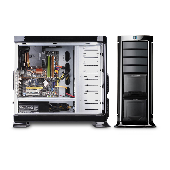
Advertisement

Related Manuals for ZALMAN GS1000 PLUS


Summary of Contents for ZALMAN GS1000 PLUS
- Page 1 GS1000 PLUS English version www.zalman.com...
- Page 2 GS1000 PLUS Contents 1. Cautionary Notes 2. Specifications 3. Parts List 4. Installation 5. Options 6. Quality Assurance and Warranty Information...
- Page 3 9) The specifications of any product may change without prior notice to improve performance Disclaimer) Zalman Tech Co., Ltd. is not responsible for any damages due to extemal causes, including but not limited to, improper use, problems with electrical power, accident, neglect, alternation,...
- Page 4 Enclosure Type Full Tower Dimensions 260(W) x 570 (H) x 640(D)mm (10.2 x 22.4 x 25.1”) 13.5kg (29.7 Ib) Weight Materials Aluminum, Plastic, Steel Color Black Motherboard Compatibility Standard ATX / Micro ATX / E-ATX Standard ATX / ATX 12V Power supply Compatibility PCI/AGP Card Compatibility Full Size, 350mm (13.7”)
- Page 5 GS1000 PLUS 1) GS1000 PLUS POWER USB 2.0 Headphones e-SATA Front View Rear View Top View Side View...
- Page 6 GS1000 PLUS 2) GS1000 PLUS Blow-Up Diagram Part No. Part Name Part No. Part Name HDD Cover Side Panel HDD Tray PSU Bracket 2 in 1 Bracket PSU Fan Bracket 5.25 Bay Cover Rear Foot Chassis Front Foot Top Cover...
- Page 10 GS1000 PLUS 4) Motherboard Installation M/B Stand Off micro ATX motherboard Server motherboard When installing a micro ATX or server motherboard, please install the M/B Stand Offs as shown in the diagram. 5) Hot Swap HDD Installation (1) 3.5 〞 HDD Removal...
- Page 12 GS1000 PLUS 6) 5.25 Drive Installation (1) ODD Installation (2) FDD Installation (3) HDD Installation (additional HDD installation in a 5.25 bay)
- Page 13 GS1000 PLUS 7) Hot Swap S-ATA Port 4-Pin Power Port Rear Front S-ATA Cable 4-Pin Power Cable Hot Swap PCB (1) Connect the Motherboard and Hot Swap PCB with the S-ATA cable. (2) Connect the 4-Pin Power Cable to the Hot Swap PCB.
- Page 14 GS1000 PLUS 8) Front I/O Cable Connection For USB 2.0, e-SATA, and audio components, please refer to the motherboard's manual. Caution Mixing the e-SATA and USB2.0 cables can cause severe damage to the system. The Power LED will not function properly if connected with the wrong polarity (+/-).
- Page 15 GS1000 PLUS 2) Optional Bottom Panel 120mm Fan Installation Bottom Panel Center Fan Installation Bottom Panel Rear Fan Installation 3) HDD Cover Fan Removal Open the HDD Cover and remove the Fan Detach the Fan Bracket from the Fan. Bracket.
Need help?
Do you have a question about the GS1000 PLUS and is the answer not in the manual?
Questions and answers