
Related Manuals for ABB VortexMaster FSV430


Summary of Contents for ABB VortexMaster FSV430
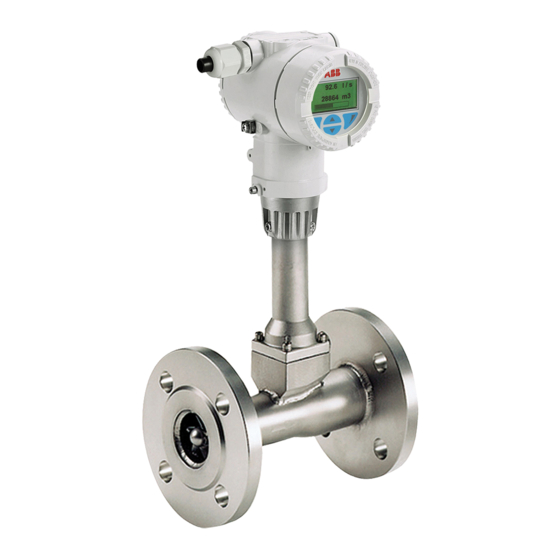
- Page 1 Commissioning and safety instruction CI/FSV/FSS/430/450-EN Rev. G VortexMaster FSV430, FSV450 SwirlMaster FSS430, FSS450 Vortex and Swirl flowmeter Measurement made easy...
- Page 2 Tel: +86(0) 21 6105 6666 Fax: +86(0) 21 6105 6677 Customer service center Mail: china.instrumentation@cn.abb.com Tel: +49 180 5 222 580 Mail: automation.service@de.abb.com Change from one to two columns 2 CI/FSV/FSS/430/450-EN Rev. G | VortexMaster FSV430, FSV450 SwirlMaster FSS430, FSS450...
-
Page 3: Table Of Contents
5.1.8 Use of trace heating ........... 23 10.1 Return form ............62 Environmental conditions ........23 5.2.1 FSV430, FSV450 ..........23 VortexMaster FSV430, FSV450 SwirlMaster FSS430, FSS450 | CI/FSV/FSS/430/450-EN Rev. G 3... -
Page 4: Safety
The signal word "NOTICE" is not a signal word indicating a name plate or welding/soldering on parts. danger to personnel. The signal word "NOTICE" can also — Material removal, e.g. by spot drilling the housing. refer to material damage. 4 CI/FSV/FSS/430/450-EN Rev. G | VortexMaster FSV430, FSV450 SwirlMaster FSS430, FSS450... -
Page 5: Use In Potentially Explosive Atmospheres
S9 = S2 + S1 + S6 cFMus NA + IS F8 = F3 + F4 cFMus NA + IS + XP-IS F9 = F3 + F4 + F1 VortexMaster FSV430, FSV450 SwirlMaster FSS430, FSS450 | CI/FSV/FSS/430/450-EN Rev. G 5... -
Page 6: Assembly And Operating Instructions
EN TR50404 and IEC 60079-32-1 standards must be observed! Instructions on cleaning The painted surface of the device may be cleaned only using a moist cloth. 6 CI/FSV/FSS/430/450-EN Rev. G | VortexMaster FSV430, FSV450 SwirlMaster FSS430, FSS450... -
Page 7: Temperature Resistance For The Connecting Cables
8.0 mm (0.31") and 11.7 mm (0.46"). NOTICE The flame-resistant pipe fitting must be assembled in accordance with the manufacturer's assembly instructions supplied with the pipe fitting. VortexMaster FSV430, FSV450 SwirlMaster FSS430, FSS450 | CI/FSV/FSS/430/450-EN Rev. G 7... -
Page 8: Electrical Connections
The digital output can be changed over to "optoelectronic coupler" if required. — NAMUR with switching amplifier — Digital output Ex nA: U = 16 ... 30 V, I = 2 ... 30 mA 8 CI/FSV/FSS/430/450-EN Rev. G | VortexMaster FSV430, FSV450 SwirlMaster FSS430, FSS450... -
Page 9: Electrical Data
It must be ensured that the overvoltage is limited to 140 % (HART: 63 V DC or Modbus: 42 V DC) of the maximum operating voltage U VortexMaster FSV430, FSV450 SwirlMaster FSS430, FSS450 | CI/FSV/FSS/430/450-EN Rev. G 9... -
Page 10: Temperature Data
≤ 36 °C 280 °C ≤ 34 °C 400 °C ≤ 40 °C 90 °C ≤ 37 °C 180 °C ≤ 36 °C 280 °C ≤ 34 °C 400 °C 10 CI/FSV/FSS/430/450-EN Rev. G | VortexMaster FSV430, FSV450 SwirlMaster FSS430, FSS450... -
Page 11: Zone 0, 1, 20, 21 - Type Of Protection "Intrinsically Safe
The digital output can be changed over to "optoelectronic ≤ 34 °C 400 °C coupler" if required. — NAMUR with switching amplifier — Digital output: Ex ia: U = 30 V DC VortexMaster FSV430, FSV450 SwirlMaster FSS430, FSS450 | CI/FSV/FSS/430/450-EN Rev. G 11... -
Page 12: Electrical And Temperature Data
For the operation in the ignition protection type "Intrinsic safety / Intrinsically safe", the current circuits on the device must be connected over approved, electrically isolated safety barriers. Change from two to one column 12 CI/FSV/FSS/430/450-EN Rev. G | VortexMaster FSV430, FSV450 SwirlMaster FSS430, FSS450... -
Page 13: Limit Value Tables
≤ 50 °C 400 °C ≤ 44 °C 90 °C 30 V 30 mA 1.0 W ≤ 41 °C 180 °C ≤ 40 °C 280 °C ≤ 38 °C 400 °C VortexMaster FSV430, FSV450 SwirlMaster FSS430, FSS450 | CI/FSV/FSS/430/450-EN Rev. G 13... - Page 14 ≤ 34 °C 400 °C ≤ 40 °C 90 °C 30 V 30 mA 1.0 W ≤ 37 °C 180 °C ≤ 36 °C 280 °C ≤ 34 °C 400 °C 14 CI/FSV/FSS/430/450-EN Rev. G | VortexMaster FSV430, FSV450 SwirlMaster FSS430, FSS450...
- Page 15 90 °C 30 V 30 mA 1.0 W ≤ 41 °C 180 °C ≤ 40 °C 280 °C ≤ 38 °C 400 °C Change from one to two columns VortexMaster FSV430, FSV450 SwirlMaster FSS430, FSS450 | CI/FSV/FSS/430/450-EN Rev. G 15...
-
Page 16: Zone 1, 21 - Type Of Protection "Flameproof (Enclosure)
Ex d ia IIC T6 Gb / Ga DIP A21 Ta 85 °C For electrical parameters, see certificate GYJ14.1088X Power supply Ex d ia Gb/Ga: U = 12 ... 42 V DC 16 CI/FSV/FSS/430/450-EN Rev. G | VortexMaster FSV430, FSV450 SwirlMaster FSS430, FSS450... -
Page 17: Electrical And Temperature Data
Devices of explosion protection class of "flameproof enclosure / Flameproof enclosure" are equipped with flameproof open joints in the housing. Contact ABB before commencing repair work. Change from two to one column VortexMaster FSV430, FSV450 SwirlMaster FSS430, FSS450 | CI/FSV/FSS/430/450-EN Rev. G 17... -
Page 18: Product Identification
For this, 4 lines of 32 characters each are provided. Change from one to two columns 18 CI/FSV/FSS/430/450-EN Rev. G | VortexMaster FSV430, FSV450 SwirlMaster FSS430, FSS450... -
Page 19: Transport And Storage
— Carrying straps must be used to transport flange designs smaller than DN 350 — Wrap the straps around both process connections when lifting the device Chains should not be used, since these may damage the housing. VortexMaster FSV430, FSV450 SwirlMaster FSS430, FSS450 | CI/FSV/FSS/430/450-EN Rev. G 19... -
Page 20: Installation
Suitable damping devices (e.g. accordance with DIN 28545 (α/2 = 8°). air vessels) might need to be fitted. 20 CI/FSV/FSS/430/450-EN Rev. G | VortexMaster FSV430, FSV450 SwirlMaster FSS430, FSS450... -
Page 21: Avoiding Cavitation
C Pipe reduction min. 15 x DN min. 5 x DN D Pipe extension min. 18 x DN min. 5 x DN VortexMaster FSV430, FSV450 SwirlMaster FSS430, FSS450 | CI/FSV/FSS/430/450-EN Rev. G 21... -
Page 22: Installation For External Pressure And Temperature
Suitable damping devices (such as air vessels if using a compressor for conveying) may need to be used. The SwirlMaster FSS400 is particularly well suited for such arrangements. 22 CI/FSV/FSS/430/450-EN Rev. G | VortexMaster FSV430, FSV450 SwirlMaster FSS430, FSS450... -
Page 23: Sensor Insulation
G11788-01 Fig. 15: Measuring medium temperature T dependent on the medium ambient temperature T amb. 1 Permissible temperature range standard version 2 Permissible temperature range high temperature version (option) VortexMaster FSV430, FSV450 SwirlMaster FSS430, FSS450 | CI/FSV/FSS/430/450-EN Rev. G 23... -
Page 24: Fss430, Fss450
122 212 302 392 482 536 572 662 752 [°F] TS [°C / °F] G11800-01 Fig. 18: Process connection of ASME flange (stainless steel) 1 Range for high-temperature design 24 CI/FSV/FSS/430/450-EN Rev. G | VortexMaster FSV430, FSV450 SwirlMaster FSS430, FSS450... - Page 25 -76 -22 32 86 140 194 248 302 356 410 464 518 [°F] 572 626 680 734 TS [°C / °F] G11802 Fig. 21: ASME wafer type process connection 1 Range for high-temperature design VortexMaster FSV430, FSV450 SwirlMaster FSS430, FSS450 | CI/FSV/FSS/430/450-EN Rev. G 25...
-
Page 26: Fss430, Fss450
To ensure that the flow profile is not distorted, the gaskets CL 300 must not protrude into the piping. CL 150 400 [°C] 122 212 752 [°F] TS [°C / °F] G11790 Fig. 23: ASME flange process connection 26 CI/FSV/FSS/430/450-EN Rev. G | VortexMaster FSV430, FSV450 SwirlMaster FSS430, FSS450... -
Page 27: Centering The Wafer Type Design
Depending on the nominal pressure rating, sleeves for the bolts, a centering ring (up to DN 80 [3"]) or segments can be ordered as additional accessories. VortexMaster FSV430, FSV450 SwirlMaster FSS430, FSS450 | CI/FSV/FSS/430/450-EN Rev. G 27... -
Page 28: Opening And Closing The Housing
After several weeks, increased force will be required to unscrew the housing cover. This is not caused by the threads, but instead is due to the type of gasket. 28 CI/FSV/FSS/430/450-EN Rev. G | VortexMaster FSV430, FSV450 SwirlMaster FSS430, FSS450... -
Page 29: Electrical Connections
Fig. 29: Installing the connecting cables The electrical connection information in this manual must be 1 Drip loop observed; otherwise, the IP rating may be adversely affected. Ground the measurement system according to requirements. VortexMaster FSV430, FSV450 SwirlMaster FSS430, FSS450 | CI/FSV/FSS/430/450-EN Rev. G 29... -
Page 30: Cable Entries
VortexMaster / SwirlMaster. 2. Insert the forked cable lug for functional grounding between the two metal tabs and into the loosened terminal. 3. Tighten the screw terminal. 30 CI/FSV/FSS/430/450-EN Rev. G | VortexMaster FSV430, FSV450 SwirlMaster FSS430, FSS450... -
Page 31: Devices With Hart Communication
DIGITAL OUTPUT 4- Digital output, negative pole from the network. ANALOG INPUT + Analog input 4 ... 20 mA for remote transmitter, e.g. for temperature, pressure, etc. ANALOG INPUT - VortexMaster FSV430, FSV450 SwirlMaster FSS430, FSS450 | CI/FSV/FSS/430/450-EN Rev. G 31... -
Page 32: Devices With Modbus Communication
Digital output, positive pole DIGITAL OUTPUT 2 Bridge after terminal 1+, NAMUR output deactivated DIGITAL OUTPUT 3 Bridge after terminal 4-, NAMUR output activated DIGITAL OUTPUT 4- Digital output, negative pole 32 CI/FSV/FSS/430/450-EN Rev. G | VortexMaster FSV430, FSV450 SwirlMaster FSS430, FSS450... -
Page 33: Electrical Data For Inputs And Outputs
= 250 Ω. The load R is calculated as a function of the available supply voltage U and the selected signal current I as follows: Load resistance Supply voltage Signalstrom VortexMaster FSV430, FSV450 SwirlMaster FSS430, FSS450 | CI/FSV/FSS/430/450-EN Rev. G 33... - Page 34 1 Terminal points in separate cable junction box 2 VortexMaster FSV430, FSV450 SwirlMaster FSS430, FSS450 3 Power supply VortexMaster FSV430, FSV450 SwirlMaster FSS430, FSS450 4 Remote transmitter 5Power supply of remote transmitter 34 CI/FSV/FSS/430/450-EN Rev. G | VortexMaster FSV430, FSV450 SwirlMaster FSS430, FSS450...
- Page 35 The VortexMaster / SwirlMaster cannot communicate with a control system or configuration tool via HART while the pressure transmitter is communicating in BURST mode, because the BURST signal has priority over cyclical HART communication. VortexMaster FSV430, FSV450 SwirlMaster FSS430, FSS450 | CI/FSV/FSS/430/450-EN Rev. G 35...
-
Page 36: Connection To Remote Mount Design
— Provide the wires on the measuring sensor side with wire- end ferrules (0.75 mm — Twist the wires to the transmitter side and solder. 36 CI/FSV/FSS/430/450-EN Rev. G | VortexMaster FSV430, FSV450 SwirlMaster FSS430, FSS450... -
Page 37: Connecting The Signal Cable
Ground terminal (functional ground / shield) NOTICE The shielding of the signal cable also serves as a functional ground and must be connected to the sensor and to the transmitter on both sides. VortexMaster FSV430, FSV450 SwirlMaster FSS430, FSS450 | CI/FSV/FSS/430/450-EN Rev. G 37... -
Page 38: Commissioning
— For devices with a remote mount design, ensure that the sensor and transmitter are assigned correctly. 38 CI/FSV/FSS/430/450-EN Rev. G | VortexMaster FSV430, FSV450 SwirlMaster FSS430, FSS450... - Page 39 The power supply to the transmitter must be briefly interrupted in order for the modified setting to take effect. The interface for the LCD indicator is also used as the service port for device configuration. VortexMaster FSV430, FSV450 SwirlMaster FSS430, FSS450 | CI/FSV/FSS/430/450-EN Rev. G 39...
-
Page 40: Switch On The Power Supply
Analog In Value No function HART In Value No function Low Flow Cutoff Iout at Alarm Low Alarm Value Low Alarm Value 3.55 mA High Alarm Value 22 mA 40 CI/FSV/FSS/430/450-EN Rev. G | VortexMaster FSV430, FSV450 SwirlMaster FSS430, FSS450... -
Page 41: Parameterization Via The "Easy Setup" Menu Function
Next Edit Enter Password 1. Use to call up the edit mode. ********** 2. Use to select the desired operating mode. RSTUVWXYZ 12345 3. Confirm the selection with Next VortexMaster FSV430, FSV450 SwirlMaster FSS430, FSS450 | CI/FSV/FSS/430/450-EN Rev. G 41... - Page 42 3. Confirm the selection with 5. With the help of set the pulses per unit (Pulse on DO) or the upper frequency (Freq on DO). 6. Confirm the selection with 42 CI/FSV/FSS/430/450-EN Rev. G | VortexMaster FSV430, FSV450 SwirlMaster FSS430, FSS450...
- Page 43 6. Confirm the selection with 1. Use to call up the edit mode. 2. Use to set the desired damping for the respective process value. 3. Confirm the selection with VortexMaster FSV430, FSV450 SwirlMaster FSS430, FSS450 | CI/FSV/FSS/430/450-EN Rev. G 43...
- Page 44 — The sensor is completely filled with the medium to be measured Easy Setup Auto Zero Next Edit — Use to start automatic adjustment of the zero point for the system. Change from two to one column 44 CI/FSV/FSS/430/450-EN Rev. G | VortexMaster FSV430, FSV450 SwirlMaster FSS430, FSS450...
-
Page 45: Hart Variables
Meter standard partial Standard volume volume Steam Act. Volume Operating volume Temperature Totalizer volumes — Steam/Water Mass Mass Temperature Totalizer mass Operating volume Steam/Water Energy Energy Temperature Totalizer energy Mass VortexMaster FSV430, FSV450 SwirlMaster FSS430, FSS450 | CI/FSV/FSS/430/450-EN Rev. G 45... - Page 46 Steam/Water Mass Temperatur Totalizer Operating Totalizer — — — — Mass mass volume volumes Steam/Water Energy Temperatur Totalizer Operating Totalizer Mass Totalizer — — Energy energy volume volumes mass 46 CI/FSV/FSS/430/450-EN Rev. G | VortexMaster FSV430, FSV450 SwirlMaster FSS430, FSS450...
-
Page 47: Operating Mode
3) The connection via the analog input or HART input is described in the chapter titled "Electrical connections" on page 29. VortexMaster FSV430, FSV450 SwirlMaster FSS430, FSS450 | CI/FSV/FSS/430/450-EN Rev. G 47... - Page 48 HART input. If both the analog input and the HART input are deactivated as a temperature input, the system uses the default density value. 48 CI/FSV/FSS/430/450-EN Rev. G | VortexMaster FSV430, FSV450 SwirlMaster FSS430, FSS450...
- Page 49 7) If for the menu item Device Setup / Plant/Customized -> Gas Std. Mode the selection is set to "Gas linear.", the compression factor is reset to 1.0. See also the chapter titled "Special operating modes" in the operating instruction. VortexMaster FSV430, FSV450 SwirlMaster FSS430, FSS450 | CI/FSV/FSS/430/450-EN Rev. G 49...
- Page 50 11) In order to implement the "Steam/Water Mass" mode with external density determination, in the menu Device Setup / Plant/Customized / Compensation Setting -> Density Selection the selection "Ext. Density" must be made. 50 CI/FSV/FSS/430/450-EN Rev. G | VortexMaster FSV430, FSV450 SwirlMaster FSS430, FSS450...
- Page 51 13) Two different properties of steam are supported: saturated steam and overheated steam. The end user can change this in the Device Setup / Plant/Customized / Compensation Setting -> Water/Steam Type menu item. 14) Required only for net energy calculation of the actually consumed energy Change from one to two columns VortexMaster FSV430, FSV450 SwirlMaster FSS430, FSS450 | CI/FSV/FSS/430/450-EN Rev. G 51...
-
Page 52: Special Operating Modes
— Net energy: The amount of energy that flows through the device is recorded. Any energy re-flow in form of condensate is deducted again from the amount of energy. For this, an additional external temperature transmitter must be connected. 52 CI/FSV/FSS/430/450-EN Rev. G | VortexMaster FSV430, FSV450 SwirlMaster FSS430, FSS450... - Page 53 (29) (58) (87) (116) (145) (174) (203) (232) (261) (290) (319) (348) p [bar abs (psia)] G11883 Fig. 49: Saturated steam density vs. pressure ρ Steam density p Pressure VortexMaster FSV430, FSV450 SwirlMaster FSS430, FSS450 | CI/FSV/FSS/430/450-EN Rev. G 53...
- Page 54 Application example (broken line in diagram) Superheated steam with 225°C, 9 bar abs (437 °F, 130 psia). It yields a steam density of approx. 4.1 kg/m (0.26 lb/ft Change from two to one column 54 CI/FSV/FSS/430/450-EN Rev. G | VortexMaster FSV430, FSV450 SwirlMaster FSS430, FSS450...
- Page 55 The steam mass is calculated using the density value that is supplied either via the analog input, the HART input, or as a constant (parameter "Preset Density "). Detection of wet steam / overheated steam is not possible with this calculation method. VortexMaster FSV430, FSV450 SwirlMaster FSS430, FSS450 | CI/FSV/FSS/430/450-EN Rev. G 55...
- Page 56 The entered density will not be used for compensation purposes. The entered density should be calculated in accordance with the typical (maximum) operating conditions. Change from one to two columns 56 CI/FSV/FSS/430/450-EN Rev. G | VortexMaster FSV430, FSV450 SwirlMaster FSS430, FSS450...
-
Page 57: Natural Gas Calculation In Accordance With Aga8 / Sgerg88
Automatic zero point balancing is started in the "Device Setup / Plant/Customized / Field optimization / Auto Zero" menu. NOTICE If the results of automatic zero point balancing are not acceptable, manual zero point balancing can be performed. VortexMaster FSV430, FSV450 SwirlMaster FSS430, FSS450 | CI/FSV/FSS/430/450-EN Rev. G 57... -
Page 58: Operation
LCD display. appears here and the operator pages are automatically displayed one after the other. Call up configuration level. The device is protected against changes to parameterization. 58 CI/FSV/FSS/430/450-EN Rev. G | VortexMaster FSV430, FSV450 SwirlMaster FSS430, FSS450... -
Page 59: Switching To The Information Level (Operator Menu)59
Standard All the parameters can be altered. Signal view Selection of submenu "Signal view" (only for Service Only Customer Service has access to the Service service purposes). menu. VortexMaster FSV430, FSV450 SwirlMaster FSS430, FSS450 | CI/FSV/FSS/430/450-EN Rev. G 59... -
Page 60: Error Messages On The Lcd Display
Error / alarm due to device configuration. NOTICE For a detailed description of errors and information regarding troubleshooting, refer to the chapter titled "Diagnosis / Error messages" in the operating instruction. 60 CI/FSV/FSS/430/450-EN Rev. G | VortexMaster FSV430, FSV450 SwirlMaster FSS430, FSS450... -
Page 61: Maintenance
® Modbus is a registered trademark of the Modbus Organization ® Kalrez and Kalrez Spectrum are registered trademarks of DuPont Performance Elastomers. ™ Hastelloy C is a trademark of Haynes International Change from two to one column VortexMaster FSV430, FSV450 SwirlMaster FSS430, FSS450 | CI/FSV/FSS/430/450-EN Rev. G 61... -
Page 62: 10 Appendix
Which substances have come into contact with the device? We hereby state that the devices / components shipped have been cleaned and are free from any dangerous or poisonous substances. Town/city, date Signature and company stamp 62 CI/FSV/FSS/430/450-EN Rev. G | VortexMaster FSV430, FSV450 SwirlMaster FSS430, FSS450... - Page 63 Notes Notes VortexMaster FSV430, FSV450 SwirlMaster FSS430, FSS450 | CI/FSV/FSS/430/450-EN Rev. G 63...
- Page 64 Howard Road, St. Neots notice. Cambridgeshire, PE19 8EU With regard to purchase orders, the agreed particulars shall prevail. ABB does not accept any responsibility whatsoever for potential errors or Tel: +44 (0)870 600 6122 possible lack of information in this document.