Table of Contents
Advertisement
Quick Links
—
A B B M E A S U R E M E N T & A N A LY T I C S | O P E R AT I N G I N S T R U C T I O N
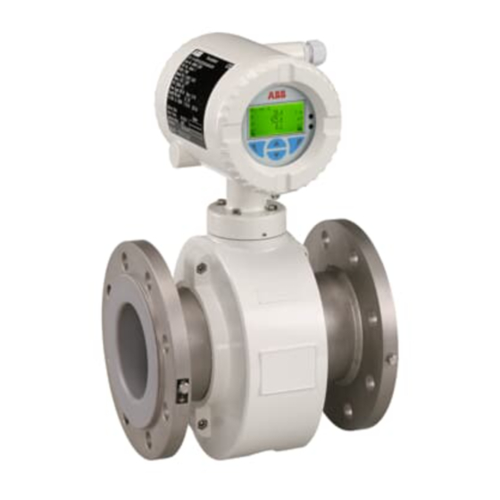
ProcessMaster wafer FEM630 minimag
Electromagnetic flowmeter
Introduction
—
FEM630
FET630
Intelligent design and extended functions for
efficient system operation at reduced costs and
with higher profitability.
ProcessMaster FEM630
The first choice for demanding applications in the
processing industry.
The wafer flowmeter that delivers
the power to solve your most
demanding process applications.
Measurement made easy
Additional Information
Additional documentation on FEM630 is available
for download free of charge at www.abb.com/flow.
Advertisement
Table of Contents

Related Manuals for ABB ProcessMaster FEM630


Summary of Contents for ABB ProcessMaster FEM630
- Page 1 FET630 Intelligent design and extended functions for Additional documentation on FEM630 is available efficient system operation at reduced costs and for download free of charge at www.abb.com/flow. with higher profitability. ProcessMaster FEM630 The first choice for demanding applications in the...
-
Page 2: Table Of Contents
F EM63 0 | E L EC TR OM AG N E T I C FLOWM E T E R | O I/F E M6 3 0-EN RE V. A Contents Health & Safety . . . . . . . . . . . . . . . . . . . . . . . . . . . . . 4 Electrical connections . - Page 3 FE M63 0 | E L EC TR OM AG N E T I C FLOWM E T E R | O I/F E M6 3 0-EN RE V. A Operation . . . . . . . . . . . . . . . . . . . . . . . . . . . . . . . . . 60 Repair .
-
Page 4: Health & Safety
F EM63 0 | E L EC TR OM AG N E T I C FLOWM E T E R | O I/F E M6 3 0-EN RE V. A Safety General information and instructions Warnings These instructions are an important part of the product and The warnings in these instructions are structured as follows: must be retained for future reference. -
Page 5: Intended Use
ABB will gladly support you in the selection, but cannot accept any liability in doing so. Improper use ABB Inc. and its affiliates are not liable for damages and / or losses related to such security breaches, any unauthorized The following are considered to be instances of improper use... -
Page 6: Warranty Provisions
This renders the manufacturer's warranty null and void. Manufacturer’s address ABB Inc. Measurement & Analytics 125 E. County Line Road Warminster, PA 18974 Tel: +1 215 674 6000... -
Page 7: Design And Function
Hastelloy C®, Platinum-Iridium, Tantalum IP rating IP65 / IP67 / IP68, NEMA 4X Approvals CRN (Canadian regulatory number) Pending Explosion protection FM / FMc Cl I, II, III Div. 1, CL I, II, III Div. 2 Additional approvals At www.abb.com/flow or on request. -
Page 8: Transmitter
• 24 V DC power supply for active outputs • Modbus® Communication Standard: HART® 7.1 Option: PROFIBUS DP®/ Modbus® Approvals Explosion protection FM / cFM Cl I Div 1, Cl II Div 2 Additional approvals At www.abb.com/flow or on request. -
Page 9: Model Variants
FE M63 0 | E L EC TR OM AG N E T I C FLOWM E T E R | O I/F E M6 3 0-EN RE V. A . . .Design and function Model variants Integral mount design For devices with an integral mount design, the transmitter ProcessMaster is available in two product series: and flowmeter sensor form a single mechanical unit. -
Page 10: Measuring Principle
F EM63 0 | E L EC TR OM AG N E T I C FLOWM E T E R | O I/F E M6 3 0-EN RE V. A . . .Design and function Measuring principle Measurements performed by the electromagnetic flowmeter are based on Faraday’s law of induction. -
Page 11: Product Identification
FE M63 0 | E L EC TR OM AG N E T I C FLOWM E T E R | O I/F E M6 3 0-EN RE V. A Product identification Name plate Marking in accordance with Pressure Equipment Directive 2014/68/EU (pending) Note Information on the relevant fluid group... -
Page 12: Transport And Storage
F EM63 0 | E L EC TR OM AG N E T I C FLOWM E T E R | O I/F E M6 3 0-EN RE V. A Transport and storage Inspection Check the devices immediately after unpacking for possible damage that may have occurred from improper transport. -
Page 13: Storing The Device
FE M63 0 | E L EC TR OM AG N E T I C FLOWM E T E R | O I/F E M6 3 0-EN RE V. A Transport and storage Storing the device Bear the following points in mind when storing devices: Store the device in its original packaging in a dry and dust- free location. -
Page 14: Installation
F EM63 0 | E L EC TR OM AG N E T I C FLOWM E T E R | O I/F E M6 3 0-EN RE V. A Installation Safety instructions Installation conditions General WARNING The following points must be observed during installation: •... -
Page 15: Devices With A Etfe Liner
Nut with washer Centering sleeve Figure 7 Assembly set for wafer type assembly (example) For devices with a wafer-type design, ABB offers an installation set as an accessory that comprises threaded rods, nuts, washers and centering sleeves for installation. Flow direction Figure 8 Flow direction The device measures the flow rate in both flow directions. -
Page 16: Electrode Axis
F EM63 0 | E L EC TR OM AG N E T I C FLOWM E T E R | O I/F E M6 3 0-EN RE V. A . . .Installation Electrode axis Minimum spacing of the devices ProcessMaster FEMxxx Electrode axis Spacing D: ≥... -
Page 17: Grounding
FE M63 0 | E L EC TR OM AG N E T I C FLOWM E T E R | O I/F E M6 3 0-EN RE V. A . . .Installation . . .Installation conditions Do not install fittings, manifolds, valves, etc., right before the flowmeter sensor. -
Page 18: Free Inlet Or Outlet
F EM63 0 | E L EC TR OM AG N E T I C FLOWM E T E R | O I/F E M6 3 0-EN RE V. A . . .Installation Free inlet or outlet Mounting with pipe vibration For a free outflow, do not install flowmeter at the highest point of the piping or on its outflow side, since the measuring tube may run empty, creating... -
Page 19: Installation In Piping With Larger Nominal
FE M63 0 | E L EC TR OM AG N E T I C FLOWM E T E R | O I/F E M6 3 0-EN RE V. A . . .Installation . . .Installation conditions Installation in piping with larger nominal diameter Reducer Figure 16 Using reducers Determine the resulting pressure loss when using reducers:... -
Page 20: Installing The Sensor
F EM63 0 | E L EC TR OM AG N E T I C FLOWM E T E R | O I/F E M6 3 0-EN RE V. A . . .Installation Installing the sensor Use the appropriate screws for the holes in accordance with Torque information on page NOTICE 136. -
Page 21: Installing The Transmitter In The Remote Mount De
FE M63 0 | E L EC TR OM AG N E T I C FLOWM E T E R | O I/F E M6 3 0-EN RE V. A . . .Installation Installing the transmitter in the remote mount design When selecting a location for the transmitter, consider the following points: •... -
Page 22: Opening And Closing The Housing
F EM63 0 | E L EC TR OM AG N E T I C FLOWM E T E R | O I/F E M6 3 0-EN RE V. A . . .Installation Opening and closing the housing DANGER Danger of explosion if the device is operated with the transmitter housing or terminal box open! While using the device in potentially explosive atmospheres before opening the transmitter housing or... -
Page 23: Adjusting The Transmitter Position
FE M63 0 | E L EC TR OM AG N E T I C FLOWM E T E R | O I/F E M6 3 0-EN RE V. A . . .Installation . . .Opening and closing the housing Adjusting the transmitter position Depending on the installation position, the transmitter NOTICE... - Page 24 F EM63 0 | E L EC TR OM AG N E T I C FLOWM E T E R | O I/F E M6 3 0-EN RE V. A . . .Installation Rotate LCD indicator – dual-compartment Rotate LCD indicator – single-compart- housing ment housing The LCD indicator can be rotated in three increments of 90°...
-
Page 25: Installing The Plug-In Cards
FE M63 0 | E L EC TR OM AG N E T I C FLOWM E T E R | O I/F E M6 3 0-EN RE V. A . . .Installation Installing the plug-in cards WARNING Loss of Ex Approval! Loss of Ex Approval due to retrofitting of plug-in cards on devices for use in potentially explosive atmospheres. - Page 26 F EM63 0 | E L EC TR OM AG N E T I C FLOWM E T E R | O I/F E M6 3 0-EN RE V. A . . .Installation . . .Installing the plug-in cards Cover LCD indicator Frontend board (FEB, with integral mount design only) Slot OC2...
- Page 27 FE M63 0 | E L EC TR OM AG N E T I C FLOWM E T E R | O I/F E M6 3 0-EN RE V. A . . .Installation . . .Installing the plug-in cards Cover LCD indicator Slot OC1 Slot OC2...
-
Page 28: Electrical Connections
F EM63 0 | E L EC TR OM AG N E T I C FLOWM E T E R | O I/F E M6 3 0-EN RE V. A Electrical connections Safety instructions Sensor grounding General information on grounding WARNING Observe the following items when grounding the device: Risk of injury due to live parts . -
Page 29: Metal Pipe With Fixed Flanges
FE M63 0 | E L EC TR OM AG N E T I C FLOWM E T E R | O I/F E M6 3 0-EN RE V. A . . .Electrical connections . . .Sensor grounding Plastic pipes, non-metallic pipes or pipes with insulating Metal pipe with fixed flanges liner G12021... -
Page 30: Grounding For Devices With Protective Plates
F EM63 0 | E L EC TR OM AG N E T I C FLOWM E T E R | O I/F E M6 3 0-EN RE V. A . . .Electrical connections . . .Sensor grounding Installation and grounding in piping with cathodic corrosion protection Grounding for devices with protective plates The installation of electromagnetic flowmeters in systems... -
Page 31: Internally Insulated Piping With Cathodic Corrosion
FE M63 0 | E L EC TR OM AG N E T I C FLOWM E T E R | O I/F E M6 3 0-EN RE V. A . . .Electrical connections . . .Sensor grounding Internally insulated piping with cathodic corrosion potential G11050 G11049... -
Page 32: Mixed System, Piping With Cathodic Corrosion Potential And Functional Ground Potential
F EM63 0 | E L EC TR OM AG N E T I C FLOWM E T E R | O I/F E M6 3 0-EN RE V. A . . .Electrical connections . . .Sensor grounding Power supply Mixed system, piping with cathodic corrosion potential Note and functional ground potential... -
Page 33: Cable Entries
FE M63 0 | E L EC TR OM AG N E T I C FLOWM E T E R | O I/F E M6 3 0-EN RE V. A . . .Electrical connections Cable entries Installing the connection cables General information on cable installation The electrical connection is made via cable entries with a ½... -
Page 34: Connection With Ip Rating Ip 68
0.75 mm2 (AWG 19) 656 ft (200 m) Recommended cables It is recommended to use an ABB signal cable with the order number 3KQZ407123U0100 for standard applications. The ABB signal cable fulfills the above-mentioned cable specification and can be utilized unrestrictedly up to an ambient temperature of Tamb = 176 °F (80 °C) - Page 35 FE M63 0 | E L EC TR OM AG N E T I C FLOWM E T E R | O I/F E M6 3 0-EN RE V. A . . .Electrical connections . . .Connection with IP rating IP 68 If the terminal box is to be potted subsequently on-site, a special two-component potting compound can be ordered Electrical connection...
-
Page 36: Pin Assignment
F EM63 0 | E L EC TR OM AG N E T I C FLOWM E T E R | O I/F E M6 3 0-EN RE V. A . . .Electrical connections Pin assignment HART 1+ 2- Uco 32 31 V3 V4 V1 V2 41 42 51... -
Page 37: Electrical Data For Inputs And Outputs
FE M63 0 | E L EC TR OM AG N E T I C FLOWM E T E R | O I/F E M6 3 0-EN RE V. A . . .Electrical connections . . .Pin assignment Current output Uco / 32, 31 / 32 Can be configured for outputting mass flow and volume Electrical data for inputs and outputs flow via the on-site software. - Page 38 F EM63 0 | E L EC TR OM AG N E T I C FLOWM E T E R | O I/F E M6 3 0-EN RE V. A . . .Electrical connections . . .Pin assignment Digital output 41 / 42, 51 / 52 Current output V1 / V2, V3 / V4 (plug-in module) Can be configured as pulse, frequency or binary output via Up to two additional plug-in modules can be implemented via...
- Page 39 FE M63 0 | E L EC TR OM AG N E T I C FLOWM E T E R | O I/F E M6 3 0-EN RE V. A . . .Electrical connections . . .Pin assignment Digital output V1 / V2, V3 / V4 (plug-in module) Digital input V1 / V2, V3 / V4 (plug-in module) The ‘digital output passive (green)’...
- Page 40 F EM63 0 | E L EC TR OM AG N E T I C FLOWM E T E R | O I/F E M6 3 0-EN RE V. A . . .Electrical connections . . .Pin assignment 24 V DC loop power supply (plug-in module) Modbus / PROFIBUS DP interface V1 / V2 (plug-in card) Use of the ‘loop power supply (blue)’...
-
Page 41: Connection Examples
FE M63 0 | E L EC TR OM AG N E T I C FLOWM E T E R | O I/F E M6 3 0-EN RE V. A . . .Electrical connections . . .Pin assignment Connection examples Digital output 41 / 42, 51 / 52 passive on distributed control system Input and output functions are configured via the device... - Page 42 F EM63 0 | E L EC TR OM AG N E T I C FLOWM E T E R | O I/F E M6 3 0-EN RE V. A . . .Electrical connections . . .Pin assignment Active current output V3 / V4 Connection versions digital output 41 / 42, 51 / 52 When the ‘loop power supply 24 V DC, blue’...
-
Page 43: Connection To Integral Mount Design
FE M63 0 | E L EC TR OM AG N E T I C FLOWM E T E R | O I/F E M6 3 0-EN RE V. A . . .Electrical connections . . .Pin assignment Connection to integral mount design Dual- compartment housing Terminals for power supply Cover for power supply terminals... - Page 44 F EM63 0 | E L EC TR OM AG N E T I C FLOWM E T E R | O I/F E M6 3 0-EN RE V. A . . .Electrical connections . . .Pin assignment NOTICE If the O-ring gasket is seated incorrectly or damaged, this may have an adverse effect on the housing protection class .
-
Page 45: Connection To Remote Mount Design
FE M63 0 | E L EC TR OM AG N E T I C FLOWM E T E R | O I/F E M6 3 0-EN RE V. A . . .Electrical connections . . .Pin assignment Connection to remote mount design Dual- compartment housing Transmitter Upper terminal box (back side) - Page 46 22 to open and close the housing safely. • Connect the cables in accordance with the electrical connection diagram. If present, connect the cable ABB signal cable HELKAMA signal cable shielding to the earthing clamp provided. Terminal...
- Page 47 22 to open and close the housing safely. • Use wire end ferrules when connecting. • From an ambient temperature of T . ≥ 140 °F (≥ 60 °C) ABB signal cable HELKAMA signal cable additionally insulate the wires with the enclosed silicone Terminal...
-
Page 48: Digital Communication
Modbus protocol The necessary DTMs and other files can be downloaded from Terminals V1 / V2 www.abb.com/flow. Configuration Via the Modbus interface or via the local operating interface in connection with Asset Vision Basic (DAT200) and a corresponding Device Type... -
Page 49: Cable Specification
Manager) format plus a GSD file. configuration (2 core or 4-core). • At a baud rate of 9600 and with a conductor cross- You can download EDD, DTM and GSD from www.abb.com/ section of at least 0.14 mm2 (AWG 26), the maximum flow. - Page 50 • Spur cable length (LS), at ≤ 1500 kBit/s: LS ≤ 10”, at > 1500 kBit/s: LS = 0.0”! • At 1500 kBit/s and ABB DP cable type A: – Sum of all spur cable lengths (LS) ≤ 21.6 ft, trunk cable length (LT) >...
-
Page 51: Commissioning
Safety instructions Hardware settings Limits and rules when using ABB fieldbus accessories Note The product has an ABB service account that can be disabled CAUTION with this write protection switch. Risk of burns due to hot measuring media Dual-compartment housing The device surface temperature may exceed 158 °F (70 °C),... -
Page 52: Configuration Of Digital Outputs V1 / V2 Or V3
F EM63 0 | E L EC TR OM AG N E T I C FLOWM E T E R | O I/F E M6 3 0-EN RE V. A . . .7 Commissioning . . .Hardware settings Single-compartment housing Configuration of digital outputs V1 / V2 or V3 / V4 DIP switch, Write protection NAMUR rotary switch... -
Page 53: Checks Prior To Commissioning
Parameterization of the device By combining the HART-DTM and the softwareflow available at www.abb.com/ABB AssetVision, all parameters can also be The FEM630 can be commissioned and operated via the set without a fieldbus connection. -
Page 54: Parameterization Via The Infrared Service Port
By combining the HART-DTM and the software ‘flow’ available at www.abb.com/ABB AssetVision, all parameters can also be set without a HART connection. PC / Notebook running ABB AssetVision and HART DTM HART modem Power supply unit Figure 66 HART Modem on the transmitter (example) -
Page 55: Factory Settings
FE M63 0 | E L EC TR OM AG N E T I C FLOWM E T E R | O I/F E M6 3 0-EN RE V. A . . .7 Commissioning Factory settings Parameterization via the menu function Easy Setup The device can be factory parameterized to customer specifications upon request. - Page 56 F EM63 0 | E L EC TR OM AG N E T I C FLOWM E T E R | O I/F E M6 3 0-EN RE V. A . . .7 Commissioning ...Parameterization via the menu function Easy Setup Menu Easy Setup Easy Setup...
- Page 57 FE M63 0 | E L EC TR OM AG N E T I C FLOWM E T E R | O I/F E M6 3 0-EN RE V. A . . .7 Commissioning ...Parameterization via the menu function Easy Setup Easy Setup Easy Setup Pulse Width...
- Page 58 F EM63 0 | E L EC TR OM AG N E T I C FLOWM E T E R | O I/F E M6 3 0-EN RE V. A . . .7 Commissioning ...Parameterization via the menu function Easy Setup Zero point adjustment of the flowmeter Note •...
-
Page 59: Measuring Range Table
FE M63 0 | E L EC TR OM AG N E T I C FLOWM E T E R | O I/F E M6 3 0-EN RE V. A . . .7 Commissioning Measuring range table The upper range value can be set between 0.02 × Q DN and 2 ×... -
Page 60: Operation
F EM63 0 | E L EC TR OM AG N E T I C FLOWM E T E R | O I/F E M6 3 0-EN RE V. A Operation Safety instructions The LCD indicator has capacitive operating buttons. These CAUTION enable you to control the device through the closed housing Risk of burns due to hot measuring media... -
Page 61: Menu Levels
FE M63 0 | E L EC TR OM AG N E T I C FLOWM E T E R | O I/F E M6 3 0-EN RE V. A . . .Operation Menu levels Process display Information level Configuration level (Operator Menu) (Configuration) ...Operator Page 1 to n... -
Page 62: Process Display
F EM63 0 | E L EC TR OM AG N E T I C FLOWM E T E R | O I/F E M6 3 0-EN RE V. A . . .Operation Process display Switching to the information level On the information level, the operator menu can be used to display diagnostic information and choose which operator pages to display. -
Page 63: Error Messages On The Lcd Display
Error / alarm due to device configuration. Standard All the parameters can be changed. Service Only ABB Customer Service has access to the Service Note menu. For a detailed description of errors and troubleshooting instructions, please see Diagnosis / error messages on page... - Page 64 Select a menu using Back Select Confirm the selection with 4 Contact ABB Service and request a one-time password, stating the ‘ID’ and ‘Pin’ shown. Enter the one-time password. Note The one-time password is only valid once and needs to separately requested with each password reset.
-
Page 65: Selecting And Changing Parameter
FE M63 0 | E L EC TR OM AG N E T I C FLOWM E T E R | O I/F E M6 3 0-EN RE V. A . . .Operation Selecting and changing parameter Parameter name 12.3456 [unit] Entry from table When an entry is made from a table, a value is selected from a list of parameter values. - Page 66 F EM63 0 | E L EC TR OM AG N E T I C FLOWM E T E R | O I/F E M6 3 0-EN RE V. A . . .Operation . . .Selecting and changing parameter Exiting the setup For some menu items, values must be entered.
-
Page 67: Parameter Overview
FE M63 0 | E L EC TR OM AG N E T I C FLOWM E T E R | O I/F E M6 3 0-EN RE V. A . . .Operation Parameter overview Note This overview of parameters shows all the menus and parameters available on the device. Depending on the version and configuration of the device, not all of the menus and parameters may be visible in it. - Page 68 F E M 6 3 0 | E L E C TR OM AG N E T IC F LOW M E T E R | O I/F E M6 30 - EN RE V. A . . .Operation . . .Parameter overview Transmitter Type Transmitter ID Transm.Serial No.
- Page 69 FE M63 0 | E L EC TR OM AG N E T I C FLOWM E T E R | O I/F E M6 3 0-EN RE V. A . . .Operation . . .Parameter overview Unit Massflow Qm .
- Page 70 F EM63 0 | E L EC TR OM AG N E T I C FLOWM E T E R | O I/F E M6 3 0-EN RE V. A . . .Operation . . .Parameter overview Output Value ...Curr.Out 31/32 Input Output Curr.Out Mode Curr.Out at Alarm...
- Page 71 FE M63 0 | E L EC TR OM AG N E T I C FLOWM E T E R | O I/F E M6 3 0-EN RE V. A . . .Operation . . .Parameter overview Mode ...Dig.Out V1/V2 Logic Output Action .
- Page 72 F EM63 0 | E L EC TR OM AG N E T I C FLOWM E T E R | O I/F E M6 3 0-EN RE V. A . . .Operation . . .Parameter overview Alarm history Process Alarm Clear Alarm History Maintenance Required .
- Page 73 FE M63 0 | E L EC TR OM AG N E T I C FLOWM E T E R | O I/F E M6 3 0-EN RE V. A . . .Operation . . .Parameter overview Preset Maint. cycle .
- Page 74 F EM63 0 | E L EC TR OM AG N E T I C FLOWM E T E R | O I/F E M6 3 0-EN RE V. A . . .Operation . . .Parameter overview Conductivity On/Off . . .Diagnosis Conductiv Conductivity[µS/cm] Adj.
- Page 75 FE M63 0 | E L EC TR OM AG N E T I C FLOWM E T E R | O I/F E M6 3 0-EN RE V. A . . .Operation . . .Parameter overview Tx Factory CMR .
- Page 76 F EM63 0 | E L EC TR OM AG N E T I C FLOWM E T E R | O I/F E M6 3 0-EN RE V. A . . .Operation . . .Parameter overview All Totalizer ...Reset Totalizer Totalizer Massflow Fwd Massflow Rev...
-
Page 77: Parameter Descriptions
FE M63 0 | E L EC TR OM AG N E T I C FLOWM E T E R | O I/F E M6 3 0-EN RE V. A . . .Operation Parameter descriptions Selection Code Description Available units Grams per second g/min Grams per minute... -
Page 78: Menu: Easy Setup
F EM63 0 | E L EC TR OM AG N E T I C FLOWM E T E R | O I/F E M6 3 0-EN RE V. A . . .Operation . . .Parameter descriptions Menu: Easy Setup Menu / parameter Description Easy Setup... -
Page 79: Menu: Device Info
FE M63 0 | E L EC TR OM AG N E T I C FLOWM E T E R | O I/F E M6 3 0-EN RE V. A . . .Operation . . .Parameter descriptions Menu: Device Info This menu is only used to display the device parameters. - Page 80 F EM63 0 | E L EC TR OM AG N E T I C FLOWM E T E R | O I/F E M6 3 0-EN RE V. A . . .Operation . . .Parameter descriptions Menu / parameter Device Info / .
-
Page 81: Menu: Device Setup
FE M63 0 | E L EC TR OM AG N E T I C FLOWM E T E R | O I/F E M6 3 0-EN RE V. A . . .Operation . . .Parameter descriptions Menu: Device Setup Menu / parameter Device Setup . - Page 82 F EM63 0 | E L EC TR OM AG N E T I C FLOWM E T E R | O I/F E M6 3 0-EN RE V. A . . .Operation . . .Parameter descriptions Menu / parameter Device Setup / .
- Page 83 FE M63 0 | E L EC TR OM AG N E T I C FLOWM E T E R | O I/F E M6 3 0-EN RE V. A . . .Operation . . .Parameter descriptions Menu / parameter Device Setup / .
- Page 84 F EM63 0 | E L EC TR OM AG N E T I C FLOWM E T E R | O I/F E M6 3 0-EN RE V. A . . .Operation . . .Parameter descriptions Menu / parameter Device Setup / .
- Page 85 Batchmode Indicator as to whether the filling function has been activated. Set the device-specific code to activate the filling function. To use this function subsequently, contact the ABB service team or sales organization. Batchmode Code After entering the code, restart the device (e.g. using the parameter ‘Device Reset’ or by briefly switching off the power supply).
-
Page 86: Menu: Display
F EM63 0 | E L EC TR OM AG N E T I C FLOWM E T E R | O I/F E M6 3 0-EN RE V. A . . .Operation . . .Parameter descriptions Menu / parameter Description Display Selection of menu language. -
Page 87: Menu: Input/Output
FE M63 0 | E L EC TR OM AG N E T I C FLOWM E T E R | O I/F E M6 3 0-EN RE V. A . . .Operation . . .Parameter descriptions Menu: Input/output Menu / parameter Description Input/Output ...Curr.Out 31/32... - Page 88 F EM63 0 | E L EC TR OM AG N E T I C FLOWM E T E R | O I/F E M6 3 0-EN RE V. A . . .Operation . . .Parameter descriptions Menu / parameter Description Input/Output / ...Curr.Out 31/32 Input/Output / ...Curr.Out V1/V2...
- Page 89 FE M63 0 | E L EC TR OM AG N E T I C FLOWM E T E R | O I/F E M6 3 0-EN RE V. A . . .Operation . . .Parameter descriptions Menu / parameter Description Input/Output / ...Dig.Out 41/42 / ...Setup Pulse Output Selection of process variable that is issued via the pulse output.
- Page 90 F EM63 0 | E L EC TR OM AG N E T I C FLOWM E T E R | O I/F E M6 3 0-EN RE V. A . . .Operation . . .Parameter descriptions Menu / parameter Description Input/Output / ...Dig.Out 41/42 / ...Alarm Config General Alarm...
- Page 91 FE M63 0 | E L EC TR OM AG N E T I C FLOWM E T E R | O I/F E M6 3 0-EN RE V. A . . .Operation . . .Parameter descriptions Menu / parameter Description Input/Output / ...Dig.Out 51/52 / ...Setup Logic Output Selection of binary output function.
- Page 92 F EM63 0 | E L EC TR OM AG N E T I C FLOWM E T E R | O I/F E M6 3 0-EN RE V. A . . .Operation . . .Parameter descriptions Menu / parameter Description Input/Output / ...Dig.Out V1/V2 / ...Setup Logic Output Input/Output / ...Dig.
-
Page 93: Menu: Process Alarm
FE M63 0 | E L EC TR OM AG N E T I C FLOWM E T E R | O I/F E M6 3 0-EN RE V. A . . .Operation . . .Parameter descriptions Menu: Process Alarm Menu / parameter Description Process Alarm... -
Page 94: Menu: Communication
HART Message Display of the alphanumeric TAG number. HART Manuf. ID Display of the HART manufacturer ID. ABB = 26 HART Device ID Display of the HART device ID. Select whether the transmitter must respond to the HART command 73 (Find Device). - Page 95 Set the PROFIBUS DP® device address (1 to 126). Display the PROFIBUS DP® identification number • 9700: 1xAI Ident Nr. Selector • 9740: 1xAI + 1xTOT • 3432: ABB-specific Display the PROFIBUS communication status. • Offline: No PROFIBUS® communication. Comm State • Stop: Bus active, device not active.
-
Page 96: Menu: Diagnostics
F EM63 0 | E L EC TR OM AG N E T I C FLOWM E T E R | O I/F E M6 3 0-EN RE V. A . . .Operation . . .Parameter descriptions Menu: Diagnostics Menu / parameter Description Diagnostics . - Page 97 FE M63 0 | E L EC TR OM AG N E T I C FLOWM E T E R | O I/F E M6 3 0-EN RE V. A . . .Operation . . .Parameter descriptions Menu / parameter Description Diagnostics / .
- Page 98 F EM63 0 | E L EC TR OM AG N E T I C FLOWM E T E R | O I/F E M6 3 0-EN RE V. A . . .Operation . . .Parameter descriptions Menu / parameter Description Diagnostics / .
- Page 99 FE M63 0 | E L EC TR OM AG N E T I C FLOWM E T E R | O I/F E M6 3 0-EN RE V. A . . .Operation . . .Parameter descriptions Diagnostics / . . .Diagnosis Control / . . .Diagnosis Conductiv* Activate the conductivity diagnostic function.
- Page 100 F EM63 0 | E L EC TR OM AG N E T I C FLOWM E T E R | O I/F E M6 3 0-EN RE V. A . . .Operation . . .Parameter descriptions Menu / parameter Description Diagnostics / .
- Page 101 FE M63 0 | E L EC TR OM AG N E T I C FLOWM E T E R | O I/F E M6 3 0-EN RE V. A . . .Operation . . .Parameter descriptions Menu / parameter Description Diagnostics / .
- Page 102 F EM63 0 | E L EC TR OM AG N E T I C FLOWM E T E R | O I/F E M6 3 0-EN RE V. A . . .Operation . . .Parameter descriptions Menu / parameter Description Diagnostics / ...Output Readings Display the current values and statuses of the listed inputs and outputs.
-
Page 103: Menu: Totalizer
FE M63 0 | E L EC TR OM AG N E T I C FLOWM E T E R | O I/F E M6 3 0-EN RE V. A . . .Operation . . .Parameter descriptions Menu: Totalizer Menu / parameter Description Totalizer ...Reset Totalizer... - Page 104 F EM63 0 | E L EC TR OM AG N E T I C FLOWM E T E R | O I/F E M6 3 0-EN RE V. A . . .Operation . . .Parameter descriptions Menu / parameter Description Totalizer / ...Batching Selection of process variable used during the filling process.
- Page 105 FE M63 0 | E L EC TR OM AG N E T I C FLOWM E T E R | O I/F E M6 3 0-EN RE V. A . . .Operation . . .Parameter descriptions Menu / parameter Description Totalizer / ...Lag Correction Selection of overrun correction.
-
Page 106: Menu: Sensor Setup
Sensor TFE Function This activates or deactivates full pipe detection (TFE = complete fill electrode). Software history In accordance with NAMUR recommendation NE53, ABB offers a transparent and traceable software history. Device software package FEx630 (device firmware package) Design Issue date... -
Page 107: Filling Function
FE M63 0 | E L EC TR OM AG N E T I C FLOWM E T E R | O I/F E M6 3 0-EN RE V. A . . .Operation Filling function Setup For the configuration of the fill function, the following steps must be performed: The fill function must be active. -
Page 108: Diagnosis / Error Messages
F EM63 0 | E L EC TR OM AG N E T I C FLOWM E T E R | O I/F E M6 3 0-EN RE V. A Diagnosis / error messages Calling up the error description Additional details about the error that has occurred can be called up on the information level. -
Page 109: Error Messages
/ short circuit or defective coil defective coil fuse or humidity in the terminal service. fuse or moisture in terminal compartment. compartment. ADC RX210 com. error. Bad EMC environment or defective Replace the electronics unit or contact ABB F090.035 / Electronics Call service. component. Service. - Page 110 F EM63 0 | E L EC TR OM AG N E T I C FLOWM E T E R | O I/F E M6 3 0-EN RE V. A . . .Diagnosis / error messages . . .Error messages Error no .
- Page 111 FE M63 0 | E L EC TR OM AG N E T I C FLOWM E T E R | O I/F E M6 3 0-EN RE V. A . . .Diagnosis / error messages . . .Error messages Operation outside of specifications (Out Of Spec .) Error no .
- Page 112 F EM63 0 | E L EC TR OM AG N E T I C FLOWM E T E R | O I/F E M6 3 0-EN RE V. A . . .Diagnosis / error messages . . .Error messages Error no .
-
Page 113: Overview
FE M63 0 | E L EC TR OM AG N E T I C FLOWM E T E R | O I/F E M6 3 0-EN RE V. A . . .Diagnosis / error messages Overview Errors encountered are itemized in tabular form on the following pages. The response of the transmitter on error detection is described therein. - Page 114 F EM63 0 | E L EC TR OM AG N E T I C FLOWM E T E R | O I/F E M6 3 0-EN RE V. A . . .Diagnosis / error messages . . .Overview Error no . / Range Error text Current output Digital output...
- Page 115 FE M63 0 | E L EC TR OM AG N E T I C FLOWM E T E R | O I/F E M6 3 0-EN RE V. A . . .Diagnosis / error messages . . .Overview Error no . / Range Error text Current output Digital output...
- Page 116 F EM63 0 | E L EC TR OM AG N E T I C FLOWM E T E R | O I/F E M6 3 0-EN RE V. A . . .Diagnosis / error messages . . .Overview Error no . / Range Error text Current output Digital output...
-
Page 117: Extended Diagnostic Functions
Overview Note • The extended diagnostic functions are only available on the ProcessMaster FEM630 if the ‘Extended diagnostic functions’ software package has been ordered (see table) . • To facilitate initial commissioning, the individual diagnosis options of the extended diagnostic functions are deacti- vated (factory default). -
Page 118: Detection Of Gas Bubbles
F EM63 0 | E L EC TR OM AG N E T I C FLOWM E T E R | O I/F E M6 3 0-EN RE V. A . . .Diagnosis / error messages . . .Extended diagnostic functions Detection of gas bubbles Monitoring the conductivity Gas bubbles in the measuring medium influence the flow... -
Page 119: Monitoring The Electrode Impedance
FE M63 0 | E L EC TR OM AG N E T I C FLOWM E T E R | O I/F E M6 3 0-EN RE V. A . . .Diagnosis / error messages . . .Extended diagnostic functions Monitoring the electrode impedance Measurements on the flowmeter The measurement monitors the impedance between the... -
Page 120: Monitoring The Grounding
Requirements for use: Verification‘). • The sensor must be filled completely with measuring medium. A software tool (ABB Ability SRV500) is available for • There is no flow through the sensor (close all valves, shut- documentation and trend analysis. off devices etc.) Setup •... -
Page 121: Maintenance
• the measurement-related function • Devices for use in potentially explosive atmospheres • the leak tightness may be serviced and repaired by qualified ABB • the wear (corrosion) personnel only. • For measuring devices for potentially explosive atmospheres, observe the relevant operator guidelines. -
Page 122: Sensor
Loss of Ex approval due to replacement of components cleaning. in devices for use in potentially explosive atmospheres. • Devices for use in potentially explosive atmospheres may be serviced and repaired by qualified ABB personnel only. • For measuring devices for potentially explosive atmospheres, observe the relevant operator guidelines. -
Page 123: Spare Parts
0.8 A Nominal voltage of fuse 250 V AC 250 V AC Note Design Device fuse 5 x 20 mm Spare parts can be ordered from ABB Service. Breaking capacity 1500 A at 250 V AC www.abb.com/contacts Ordering number 3KQR000757U0100 3KQR000757U0200... -
Page 124: Replacing The Lcd Indicator
F EM63 0 | E L EC TR OM AG N E T I C FLOWM E T E R | O I/F E M6 3 0-EN RE V. A . . .11 Repair Replacing the LCD indicator Dual-compartment housing Single-compartment housing LCD indicator cable harness LCD indicator... -
Page 125: Replacing The Frontend Board
FE M63 0 | E L EC TR OM AG N E T I C FLOWM E T E R | O I/F E M6 3 0-EN RE V. A . . .11 Repair Replacing the frontend board Integral mount design LCD indicator cable harness LCD indicator Sensor cable harness... - Page 126 F EM63 0 | E L EC TR OM AG N E T I C FLOWM E T E R | O I/F E M6 3 0-EN RE V. A . . .11 Repair . . .Replacing the frontend board NOTICE Note The SensorMemory is assigned to the sensor.
-
Page 127: Remote Mount Design
FE M63 0 | E L EC TR OM AG N E T I C FLOWM E T E R | O I/F E M6 3 0-EN RE V. A . . .11 Repair Replacing the frontend board Remote mount design Frontend board fixing screw Terminals Frontend board... -
Page 128: Replacing The Sensor
• If necessary, wear suited personal protective All devices delivered to ABB must be free from any equipment when working on the device. hazardous materials (acids, alkalis, solvents, etc.). • Depressurize and empty the device / piping, allow to cool and purge if necessary. -
Page 129: Recycling And Disposal
FE M63 0 | E L EC TR OM AG N E T I C FLOWM E T E R | O I/F E M6 3 0-EN RE V. A Recycling and disposal Dismounting Disposal Note WARNING Products that are marked with the adjacent symbol may not be disposed of as unsorted municipal Risk of injury due to process conditions . -
Page 130: Specification
F EM63 0 | E L EC TR OM AG N E T I C FLOWM E T E R | O I/F E M6 3 0-EN RE V. A Specification Note The device data sheet is available in the ABB download area at www.abb.com/flow. Permitted pipe vibration... -
Page 131: Maximum Permissible Cleaning Temperature
FE M63 0 | E L EC TR OM AG N E T I C FLOWM E T E R | O I/F E M6 3 0-EN RE V. A . . .13 Specification Temperature Data Temperature Data . . .ProcessMaster – Temperature data Ambient temperature as a function of measuring medium temperature Ambient temperature as a function of measuring medium temperature Ambient temperature as a function of measuring medium temperature... -
Page 132: Processmaster - Material Load For Process
(T ) and the liner material. medium Nominal medium Lining material diameter [mbar abs] medium 1 to 4 inch (DN 25 ETFE < 266 °F (130 °C) to DN 100) Liner approvals on request; please contact ABB. -
Page 133: Material Load
FE M63 0 | E L EC TR OM AG N E T I C FLOWM E T E R | O I/F E M6 3 0-EN RE V. A . . .13 Specification . . .ProcessMaster – Material load for process connections medium medium... -
Page 134: Additional Documents
The icon on the name plate indicates the following: Note All documentation, declarations of conformity, and certificates are available in ABB's download area. www.abb.com/flow Trademarks HART is a registered trademark of FieldComm Group, Austin,... -
Page 135: Appendix
FE M63 0 | E L EC TR OM AG N E T I C FLOWM E T E R | O I/F E M6 3 0-EN RE V. A Appendix Return form Statement on the contamination of devices and components Repair and/or maintenance work will only be performed on devices and components if a statement form has been completed and submitted. -
Page 136: Torque Information
F EM63 0 | E L EC TR OM AG N E T I C FLOWM E T E R | O I/F E M6 3 0-EN RE V. A . . .15 Appendix Torque information Tightening torques for ProcessMaster Wafer Note The specified torques are valid only for greased threads and piping that is not subject to tensile stress. -
Page 137: Parameterization Overview (Factory Settings)
FE M63 0 | E L EC TR OM AG N E T I C FLOWM E T E R | O I/F E M6 3 0-EN RE V. A . . .15 Appendix Parameterization overview (factory settings) Parameter Value range Factory setting Sensor Tag Alphanumeric, maximum 20 characters. - Page 138 We reserve the right to make technical changes or modify the contents of this document without prior notice. With regard to purchase orders, the agreed particulars shall prevail. ABB does not accept any responsibility whatsoever for potential errors or possible lack of information in this document.