Sign In
Upload
Manuals
Brands
ABB Manuals
Measuring Instruments
ProcessMaster FET632
ABB ProcessMaster FET632 Manuals
Manuals and User Guides for ABB ProcessMaster FET632. We have
2
ABB ProcessMaster FET632 manuals available for free PDF download: Operating Instruction, Operating Instructions Manual
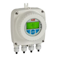
ABB ProcessMaster FET632 Operating Instruction (152 pages)
Electromagnetic flowmeter
Brand:
ABB
| Category:
Measuring Instruments
| Size: 11.48 MB
Table of Contents
Table of Contents
2
General Information and Instructions
4
Warnings
4
Intended Use
5
Improper Use
5
Use in Potentially Explosive Atmospheres
5
Notes on Data Safety
5
Warranty Provisions
6
Manufacturer's Address
6
Safety .......................................................................... 4
6
Design and Function
7
Overview
7
Processmaster
7
Hygienicmaster
8
Transmitter
9
Model Variants
10
Measuring Principle
11
Product Identification
12
Name Plate
12
Additional Warning Plate
12
Transport and Storage
13
Inspection
13
Transport
13
Storing the Device
14
Temperature Data
14
Returning Devices
14
Installation
15
Safety Instructions
15
Use in Potentially Explosive Atmospheres
15
Installation Conditions
15
General
15
Devices with Extended Diagnostic Functions
15
Brackets
16
Gaskets
16
Devices with a Wafer-Type Design
16
Flow Direction
16
Electrode Axis
17
Mounting Position
17
Minimum Spacing of the Devices
17
Grounding
18
Sensor Insulation
18
Inlet and Outlet Sections
18
Free Inlet or Outlet
19
Mounting with Heavily Contaminated Measuring Media
19
Mounting with Pipe Vibration
19
Installation in Piping with Larger Nominal Diameter
20
Installation in 3A Compliant Installations
20
Installing the Sensor
21
Installing the Transmitter in the Remote Mount Design
22
Opening and Closing the Housing
23
Adjusting the Transmitter Position
24
Installing the Plug-In Cards
26
Electrical Connections
29
Safety Instructions
29
Use in Potentially Explosive Atmospheres
29
Sensor Grounding
29
General Information on Grounding
29
Metal Pipe with Fixed Flanges
30
Metal Pipe with Loose Flanges
30
Plastic Pipes, Non-Metallic Pipes or Pipes with Insulating Liner
30
Sensor Type Hygienicmaster
31
Grounding with Conductive PTFE Grounding Plate
31
Devices with Extended Diagnostic Functions
31
Installation and Grounding in Piping with Cathodic Corrosion Protection
31
Power Supply
33
Cable Entries
34
Connection Via Cable Conduit
34
Installing the Connection Cables
34
Connection with IP Rating IP 68
35
Pin Assignment
37
Electrical Data for Inputs and Outputs
38
Connection Examples
42
Connection to Integral Mount Design
44
Connection to Remote Mount Design
46
Digital Communication
49
HART® Communication
49
Modbus® Communication
49
Cable Specification
50
PROFIBUS DP® Communication
50
Commissioning
52
Safety Instructions
52
Use in Potentially Explosive Atmospheres
52
Hardware Settings
52
Dual- Compartment Housing
52
Single-Compartment Housing
53
Configuration of Digital Outputs V1 / V2 or V3 / V4
53
Checks Prior to Commissioning
54
Parameterization of the Device
54
Parameterization Via the Local Operating Interface
54
Parameterization Via the Infrared Service Port Adapter
55
Parameterization Via HART
55
Factory Settings
56
Switching on the Power Supply
56
Parameterization Via the Menu Function Easy Setup
56
Measuring Range Table
60
Operation
61
Safety Instructions
61
Menu Navigation
61
Menu Levels
62
Process Display
63
Switching to the Information Level
63
Error Messages on the LCD Display
64
Switching to the Configuration Level (Parameterization)
64
Selecting and Changing Parameter
66
Entry from Table
66
Parameter Overview
68
Parameter Descriptions
78
Available Units
78
Menu: Easy Setup
79
Menu: Device Info
80
Menu: Device Setup
82
Menu: Display
87
Menu: Input/Output
88
Menu: Process Alarm
94
Menu: Communication
95
Menu: Diagnostics
97
Menu: Totalizer
104
Menu: Sensor Setup
107
Software History
107
Filling Function
108
Setup
108
Brief Overview of Configurations
108
Diagnosis / Error Messages
109
Calling up the Error Description
109
Error Messages
110
Overview
114
Extended Diagnostic Functions
118
Overview
118
Detection of Partial Filling
118
Detection of Gas Bubbles
119
Monitoring the Conductivity
119
Monitoring the Electrode Impedance
120
Measurements on the Flowmeter
120
Monitoring the Grounding
121
Verification
121
Fingerprint Database
121
10 Maintenance
122
Safety Instructions
122
Sensor
123
Gaskets
123
Cleaning
123
11 Repair
123
Safety Instructions
123
Spare Parts
124
Replacing the Fuse
124
Replacing the LCD Indicator
125
Replacing the Frontend Board
126
Integral Mount Design
126
Remote Mount Design
128
Replacing the Sensor
129
Returning Devices
129
12 Recycling and Disposal
130
Dismounting
130
Disposal
130
13 Specification
131
Permitted Pipe Vibration
131
Processmaster - Temperature Data
131
Maximum Permissible Cleaning Temperature
131
Maximum Ambient Temperature Depending on Measuring Medium Temperature
132
Processmaster - Material Load for Process Connections
136
Minimum Permissible Operating Pressure
136
Material Load
137
Hygienicmaster - Temperature Data
140
Maximum Permissible Cleaning Temperature
140
Maximum Ambient Temperature Depending on Measuring Medium Temperature
140
Hygienicmaster - Material Load for Process Connections
141
14 Additional Documents
142
15 Appendix
143
Return Form
143
Torque Information
144
Tightening Torques for Transducers with Design Level 'A
144
Tightening Torques for Transducers with Design Level 'B
149
Tightening Torques for Hygienicmaster with Variable Process Connections
151
Parameterization Overview (Factory Settings)
151
Advertisement
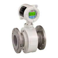
ABB ProcessMaster FET632 Operating Instructions Manual (138 pages)
Electromagnetic flowmeter
Brand:
ABB
| Category:
Measuring Instruments
| Size: 7.29 MB
Table of Contents
Table of Contents
2
1 Health & Safety
4
General Information and Instructions
4
Warnings
4
Intended Use
5
Improper Use
5
Use in Potentially Explosive Atmospheres
5
Notes on Data Safety
5
Warranty Provisions
6
Manufacturer's Address
6
2 Design and Function
7
Overview
7
Processmaster
7
Transmitter
8
Model Variants
9
Measuring Principle
10
3 Product Identification
11
Nameplate
11
Additional Warning Plate
11
4 Transport and Storage
12
Inspection
12
Transport
12
Storing the Device
13
Temperature Data
13
Returning Devices
13
5 Installation
14
Safety Instructions
14
Use in Potentially Explosive Atmospheres
14
Installation Conditions
14
General
14
Devices with Extended Diagnostic Functions
14
Devices with a ETFE Liner
15
Devices with a Wafer-Type Design
15
Flow Direction
15
Electrode Axis
16
Mounting Position
16
Minimum Spacing of the Devices
16
Grounding
17
Inlet and Outlet Sections
17
Free Inlet or Outlet
18
Mounting with Heavily Contaminated Measuring
18
Media
18
Mounting with Pipe Vibration
18
Installation in Piping with Larger Nominal
19
Diameter
19
Installing the Sensor
20
Installing the Transmitter in the Remote Mount de
21
Sign
21
Opening and Closing the Housing
22
Adjusting the Transmitter Position
23
Installing the Plug-In Cards
25
6 Electrical Connections
28
Safety Instructions
28
Use in Potentially Explosive Atmospheres
28
Sensor Grounding
28
General Information on Grounding
28
Metal Pipe with Fixed Flanges
29
Metal Pipe with Loose Flanges
29
Plastic Pipes, Non-Metallic Pipes or Pipes with
29
Insulating Liner
29
Grounding for Devices with Protective Plates
30
Grounding with Conductive PTFE Grounding
30
Plate
30
Devices with Extended Diagnostic Functions
30
Installation and Grounding in Piping with Cathodic
30
Corrosion Protection
30
Internally Insulated Piping with Cathodic Corrosion
31
Potential
31
Mixed System, Piping with Cathodic Corrosion Potential and Functional Ground Potential
32
Power Supply
32
Cable Entries
33
Connection Via Cable Conduit
33
Installing the Connection Cables
33
Connection with IP Rating IP 68
34
Pin Assignment
36
Electrical Data for Inputs and Outputs
37
Connection Examples
41
Connection to Integral Mount Design
43
Connection to Remote Mount Design
45
Digital Communication
48
HART® Communication
48
Modbus® Communication
48
Cable Specification
49
PROFIBUS DP® Communication
49
7 Commissioning
51
Safety Instructions
51
Use in Potentially Explosive Atmospheres
51
Hardware Settings
51
Dual-Compartment Housing
51
Single-Compartment Housing
51
Configuration of Digital Outputs V1 / V2 or V3
52
Checks Prior to Commissioning
53
Parameterization of the Device
53
Parameterization Via the Local Operating
53
Interface
53
Parameterization Via the Infrared Service Port
54
Adapter
54
Parameterization Via HART
54
Factory Settings
55
Switching on the Power Supply
55
Parameterization Via the Menu Function Easy Setup
55
Measuring Range Table
59
8 Operation
60
Safety Instructions
60
Menu Navigation
60
Menu Levels
61
Process Display
62
Switching to the Information Level
62
Error Messages on the LCD Display
63
Switching to the Configuration Level
63
(Parameterization)
63
Selecting and Changing Parameter
65
Entry from Table
65
Parameter Overview
67
Parameter Descriptions
77
Available Units
77
Menu: Easy Setup
78
Menu: Device Info
79
Menu: Device Setup
81
Menu: Display
86
Menu: Input/Output
87
Menu: Process Alarm
93
Menu: Communication
94
Menu: Diagnostics
96
Menu: Totalizer
103
Menu: Sensor Setup
106
Software History
106
Filling Function
107
Setup
107
Brief Overview of Configurations
107
9 Diagnosis / Error Messages
108
Calling up the Error Description
108
Error Messages
109
Overview
113
Extended Diagnostic Functions
117
Overview
117
Detection of Gas Bubbles
118
Monitoring the Conductivity
118
Monitoring the Electrode Impedance
119
Measurements on the Flowmeter
119
Monitoring the Grounding
120
Verification
120
Fingerprint Database
120
10 Maintenance
121
Safety Instructions
121
Sensor
122
Cleaning
122
11 Repair
122
Safety Instructions
122
Spare Parts
123
Replacing the Fuse
123
Replacing the LCD Indicator
124
Replacing the Frontend Board
125
Integral Mount Design
125
Remote Mount Design
127
Replacing the Sensor
128
Returning Devices
128
12 Recycling and Disposal
129
Dismounting
129
Disposal
129
13 Specification
130
Permitted Pipe Vibration
130
Processmaster - Temperature Data
130
Maximum Permissible Cleaning Temperature
131
Measuring Medium Temperature
131
Processmaster - Material Load for Process
132
Connections
132
Minimum Permissible Operating Pressure
132
Material Load
133
14 Additional Documents
134
15 Appendix
135
Return Form
135
Torque Information
136
Parameterization Overview (Factory Settings)
137
Advertisement
Related Products
ABB FET525
ABB FET325
ABB FET630
ABB FEP515
ABB FEF series
ABB HygienicMaster FEH630 series
ABB HygienicMaster FEH631
ABB HygienicMaster FEH611
ABB HygienicMaster FEH610
ABB ProcessMaster FEP631
ABB Categories
Industrial Equipment
Controller
Measuring Instruments
Battery Charger
DC Drives
More ABB Manuals
Login
Sign In
OR
Sign in with Facebook
Sign in with Google
Upload manual
Upload from disk
Upload from URL