Table of Contents
Troubleshooting

Related Manuals for Canon D1300 Series


Summary of Contents for Canon D1300 Series
- Page 1 MF5900/MF6100/D1300 Series Service Manual Rev.2 Product Overview Technical Overview Periodical Services Disassembly/Assembly F-0-1 Adjustment Trouble Shooting Error Codes Service Mode Appendex...
- Page 2 Canon will release technical information as the need arises. In the event of major This manual is copyrighted with all rights reserved. Under the copyright laws, this manual changes in the contents of this manual over a long or short period, Canon will issue a new may not be copied, reproduced or edition of this manual.
- Page 3 Explanation of Symbols The following rules apply throughout this Service Manual: 1. Each chapter contains sections explaining the purpose of specific functions and the The following symbols are used throughout this Service Manual. relationship between electrical and mechanical systems with reference to the timing of operation.
-
Page 4: Table Of Contents
Name of Parts ------------------------------------------------------------------1-8 Safety -----------------------------------------------------------------------------------------2-12 External View ----------------------------------------------------------------------- 1-8 Low-voltage Power Supply Unit Failure Detection --------------------------------2-12 MF5900/6100 Series----------------------------------------------------------------------- 1-8 Power-Saving Mode ----------------------------------------------------------------------2-12 D1300 Series -------------------------------------------------------------------------------- 1-9 Service Tasks ----------------------------------------------------------------------2-13 Cross Sectional View ------------------------------------------------------------1-10 Action for Parts Replacement ----------------------------------------------------------2-13 MF5900/6100 Series----------------------------------------------------------------------1-10 Maintenance --------------------------------------------------------------------------------2-13... - Page 5 PCB -------------------------------------------------------------------------------------------- 4-7 Notes On Service Works -----------------------------------------------------------------2-22 Connector Layout Drawing ------------------------------------------------------ 4-8 Pickup / Feed System ------------------------------------------------------ 2-24 External Cover (D1300 Series) ------------------------------------------ 4-12 Outline -------------------------------------------------------------------------------2-24 Removing the Left Cover Unit -------------------------------------------------4-12 Drive Configuration ---------------------------------------------------------------2-24 Removing the Left Rear Cover ------------------------------------------------4-14...
- Page 6 Laser Scanner System ---------------------------------------------------- 4-58 Removing the Right Cover Unit -----------------------------------------------4-15 Removing the Front Cover Unit -----------------------------------------------4-17 Removing the Laser Scanner Unit --------------------------------------------4-58 Image Forming System ---------------------------------------------------- 4-59 Removing the Rear Cover Unit ------------------------------------------------4-18 Removing the Upper Cover ----------------------------------------------------4-19 Removing the Transfer Roller --------------------------------------------------4-59 External Cover (MF5900/MF6100) ------------------------------------- 4-20 Removing the Registration Unit -----------------------------------------------4-60 Removing the Left Cover Unit -------------------------------------------------4-20...
- Page 7 Overview of Upgrading ----------------------------------------------------------- 6-6 CLEAR ---------------------------------------------------------------------------------------8-14 MISC-R ---------------------------------------------------------------------------------------8-14 Firmware Configuration ---------------------------------------------------------- 6-6 MISC-P ---------------------------------------------------------------------------------------8-14 Preparation -------------------------------------------------------------------------- 6-7 SYSTEM -------------------------------------------------------------------------------------8-15 Necessary System Environment -------------------------------------------------------- 6-7 SPLMAN -------------------------------------------------------------------------------------8-15 Before Downloading the System Software ------------------------------------------- 6-7 INSTALL --------------------------------------------------------------------------------------8-16 Downloading the System Software -------------------------------------------- 6-8 OPTION -----------------------------------------------------------------------------8-17 Procedure of Downloading --------------------------------------------------------------- 6-8 BODY -----------------------------------------------------------------------------------------8-17...
- Page 8 DAM -------------------------------------------------------------------------------------------8-30 TESTMODE ------------------------------------------------------------------ 8-31 PRINT --------------------------------------------------------------------------------8-31 FAX -----------------------------------------------------------------------------------8-32 MODEM --------------------------------------------------------------------------------------8-32 FACULTY ------------------------------------------------------------------------------------8-33 Appendex Service Tools -------------------------------------------------------------------9-2 Special Tools ------------------------------------------------------------------------ 9-2 Solvents and Oils ------------------------------------------------------------------ 9-2 General Timing Chart --------------------------------------------------------9-3 General Circuit Diagram -----------------------------------------------------9-4 General Circuit Diagram (1/2) -------------------------------------------------- 9-4 General Circuit Diagram (2/2) -------------------------------------------------- 9-5 Backup Data --------------------------------------------------------------------9-6...
-
Page 9: Safety Precautions
Safety Precautions ■ CDRH Provisions ■ Laser Safety ■ Toner Safety ■ Notes When Handling A Battery ■ Notes On Assembly/Disassembly... -
Page 10: Cdrh Provisions
Safety Precautions > Laser Safety > Handling Laser Scanner Unit CDRH Provisions Laser Safety Food and Drug CDRH (Center for Devices and Radiological Health) under FDA (Food and About Laser Beams Drug Administration) enforced provisions of the section for laser and laser products on August 2, 1976. -
Page 11: Toner Safety
Safety Precautions > Notes On Assembly/Disassembly Toner Safety Notes On Assembly/Disassembly Follow the items below to assemble/disassemble the device. About Toner 1. Disconnect the power plug to avoid any potential dangers during assembling/disassembling works. Toner is a nontoxic matter composed of plastic, iron and a trace of pigments. 2. -
Page 12: Product Overview
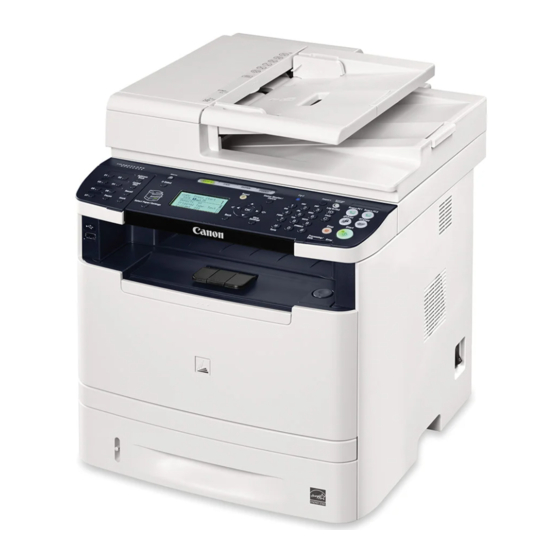
Product Overview ■ Product Lineups ■ Product Features ■ Specifications ■ Name of Parts Product Overview... -
Page 13: Main Unit
Product Overview > Product Lineups > Main Unit Product Lineups Function Canon imageCLASS Series D1320 D1350 D1370 D1380 Appearance Main Unit Function Canon imageCLASS/ i-SENSYS MF5930dn MF5950dw MF5960dn MF5940dw MF5980dn MF6160dw MF6150dw MF6140dn MF6180dw Appearance Copy Print SEND Direct Print... -
Page 14: Options
Product Overview > Product Lineups > Options Options D1300 Series MF5900/6100 Series F-1-2 Name Description Remarks [1] Canon Cassette Feeding Unit-U1 Approx. 500 Sheets (Plain paper F-1-1 60 - 89g/ m2) Name Description Remarks [2] TELEPHONE 6 KIT Long cord Cool White... -
Page 15: Product Features
Product Features Specifications Features Main Unit Specifications Compact MFP Specification/function Item The product compactified with lower height. D1300 Series MF5900/6100 Series Body Desktop (DADF standard type) Light Source Type Photosensitive Medium OPC drum Image Reading Method Contact Sensor Reading Method... - Page 16 Product Overview > Specifications > Main Unit Specifications Specification/function Specification/function Item Item D1300 Series MF5900/6100 Series D1300 Series MF5900/6100 Series LTR, LGL, A4, B5, A5, Executive, Oficio, Brazil-Oficio, Mexico- Approximately 20.6 kg Cassette Paper Size Approximately 18.3 kg (including Weight...
-
Page 17: Adf Specifications
Product Overview > Specifications > FAX Specifications ADF Specifications FAX Specifications Item Specification/function Item Specification/function Suitable Line Public Switched Telephone Network (PSTN) Original position center reference Up to 28.8Kbps in modem speed is currently available in PSTN. Note 1-sided to 1-sided copy, 2-sided to 2-sided copy, 1-sided to 2-sided that available modem speed is telephone-line dependent. -
Page 18: Print Speed
Product Overview > Specifications > Paper size Print Speed. Paper size (Unit: page/minute) (○: available -: not available) Paper type Cassette MP Tray OP Cassette Paper size Cassette Multi-purpose Tray 1-sided 2-sided 1-sided 2-sided 1-sided 2-sided A4 (210.0 mm × 297.0 mm) ○... -
Page 19: Name Of Parts
Product Overview > Name of Parts > External View > MF5900/6100 Series Name of Parts Name Name DADF (Duplex Automatic Document [13] USB Port 2 Feeder) External View Document Feeder Tray [14] Ethernet Port Document Delivery Tray [15] Left Cover Unit ■... -
Page 20: D1300 Series
Product Overview > Name of Parts > External View > D1300 Series ■ D1300 Series Name Name DADF (Duplex Automatic Document Feeder) [12] Paper Cassette Document Feeder Tray [13] USB Port 2 Document Delivery Tray [14] Ethernet Port Control Panel... -
Page 21: Cross Sectional View
Product Overview > Name of Parts > Cross Sectional View > MF5900/6100 Series 1-10 Cross Sectional View Printer ■ MF5900/6100 Series ADF/Reader Unit [10] [11] [12] [13] [14] [15] F-1-7 [16] Name Reference ADF Paper Feed Roller [17] ADF Separation Roller ADF Pickup Roller ADF Delivery roller [20]... -
Page 22: D1300 Series
Product Overview > Name of Parts > Cross Sectional View > D1300 Series 1-11 ■ D1300 Series Printer ADF / Reader Unit [10] [11] [18] [17] [12] F-1-9 [13] Name Reference ADF Paper Feed Roller [14] ADF Separation Roller [20]... -
Page 23: Operation Panel
Product Overview > Name of Parts > Operation Panel > Main Operation Panel 1-12 Operation Panel MF6100 Series [2] [3] [10] [11] [12] [13] [14] [15] ■ Main Operation Panel MF5900 Series Energy [1] [2] [10] [11] [12] [14] [15] MEDIA Menu COPY... -
Page 24: Fax Operation Panel
Product Overview > Name of Parts > Operation Panel > FAX Operation Panel 1-13 D1300 Series ■ FAX Operation Panel [1] [2] [3] [10] [11] [12] [13] [14] MF5900/6100 Series Energy Report Saver Print Menu DIRECT COPY SCAN PRINT Panel open... -
Page 25: Technical Overview
Technical Overview ■ Basic Configuration ■ Document Exposure / Delivery System ■ Controller System ■ Laser Exposure System ■ Image Formation System ■ Fixing System ■ Pickup / Feed System Technical Overview... -
Page 26: Configuration Function
Technical Overview > Basic Configuration > Basic Sequence > Basic Operational Sequence Basic Configuration Basic Sequence ■ Basic Operational Sequence Configuration Function The CPU on the Engine Controller PCB controls the operational sequence. The table below This device is roughly composed of the 6 functional blocks as shown in the figure below shows the operation and the purposes in each status from start-up of the device and to last •... -
Page 27: Print Sequence
Technical Overview > Basic Configuration > Basic Sequence > Print Sequence ■ Print Sequence Timing chart two consecutive prints on LTR paper Power switch ON Operation WAIT STBY INTR PRINT LASTR STBY TOP sensor (PS204) Fixing delivery sensor (PS915) Print start command (EEC12) Scanner Motor (M202) Laser Diode BD Output signal (BDO) -
Page 28: Print Mode
Technical Overview > Basic Configuration > Print Mode Print Mode Print modes Feeding speed Media type Print speed Remarks Normal speed 1/1speed Speed for plain paper A4/LTR 33/35 ppm mode width (60 to 89g) Transparencies 1/2 speed mode 1/2 speed Plain paper A4/LTR width (60 to 89g) Plain paper less than A4 width (60... -
Page 29: Document Exposure / Delivery System
Technical Overview > Document Exposure / Delivery System Document Exposure / Delivery System ■ Major Components Followings are the major components for Document Exposure System. ■ Specifications / Control / Function List • The Contact Sensor to scan document item function / method •... -
Page 30: Document Feeder System
Technical Overview > Document Exposure / Delivery System > Document Feeder System > Pickup/Feed/Delivery Operation Document Feeder System Operation at Duplex Reading - Pickup to Reading of the 1st side ■ Pickup/Feed/Delivery Operation The Auto Document Feeder (ADF) mounted onto this host machine is dedicated to stream- reading. -
Page 31: Original Detection
Technical Overview > Document Exposure / Delivery System > Document Feeder System > Original Detection ■ Original Detection PS703 There are two types of Original Detection in this Equipment. 1. Original Presence / Absence Detection PS702 Detected by DS (Document Sensor: PS703) Setting the original onto the original tray pushes up the actuator, activating (light shielded =>light transmitted) the DS (PS703), and resulting in detection of the presence of original. -
Page 32: Jam Detection
Technical Overview > Document Exposure / Delivery System > Service Tasks > Service Notes Service Tasks ■ Jam Detection The following cases are judged as jam. ■ Action for Parts Replacement 1. In case of delay in reaching DS/DES or stationary during scanning of original Outline of the measures is described in this section. -
Page 33: Controller System
Technical Overview > Controller System > Controls > Outline Controller System Controls ■ Outline Outline The Engine Controller controls the operational sequence of the printer. The Engine Control System controls all the other systems according to commands from the Block diagram of the Engine Controller and table of the electrical components are shown Main Controller. -
Page 34: Motor / Fan Control
Technical Overview > Controller System > Controls > Motor / Fan Control 2-10 ■ Motor / Fan Control Symbol for component Component Remarks Controller Fan The printer has one Motor for media feed and image formation. FM201 Main Fan Arrangement of Motor and the specifications are shown below. FM203 Controller Fan Motor... -
Page 35: Failure Detection
Technical Overview > Controller System > Low-voltage Power Supply > Outline 2-11 Low-voltage Power Supply ■ Failure Detection Failure Point Cause of Failure ■ Outline Main Motor In the case that the speed of Motor does not reach the specified speed after the specified time has passed since the startup of the Main Motor. -
Page 36: Protective Function
Technical Overview > Controller System > Low-voltage Power Supply > Power-Saving Mode 2-12 ■ Protective Function ■ Power-Saving Mode The Low-voltage Power Supply has a protective function against overcurrent and overvoltage This is the function to save power consumed by the printer. to prevent failures in the power supply circuit. -
Page 37: Service Tasks
Technical Overview > Controller System > Service Tasks > Service Notes 2-13 Service Tasks ■ Action for Parts Replacement Outline of the measures is described in this section. For the detailed procedure, refer to the "Chapter 5 ." ● After Replacing Main Controller PCB •... -
Page 38: Laser Exposure System
Technical Overview > Laser Exposure System > Service Tasks > Service Notes 2-14 Laser Exposure System Optical Unit Failure Detection The Optical Unit failure detection manages the Laser Scanner failure detection functions. Outline The Engine Controller determines an Optical Unit failure and notifies the Main Controller if the Laser Scanner encounters the following conditions: The Laser Exposure System forms a latent image on the photosensitive drum according to •... -
Page 39: Image Formation System
Technical Overview > Image Formation System > Image Formation Process > Outline 2-15 Image Formation System Image Formation Process Outline ■ Outline The Image-Formation process consists of the following seven steps divided among five The Image-Formation System forms a toner image on print media. functional blocks: The following are the main components of the Image-Formation system: •... -
Page 40: Latent Image Formation Block
Technical Overview > Image Formation System > Image Formation Process > Developing Block 2-16 ■ Latent Image Formation Block ■ Developing Block During the two steps that comprise this block, an invisible latent image is formed on the Toner adheres to the electrostatic latent image on the photosensitive drum, which becomes photosensitive drum. -
Page 41: Transfer Block
Technical Overview > Image Formation System > Image Formation Process > Drum Cleaning Block 2-17 ■ Transfer Block ■ Fixing Block During the two steps that comprise this block, a toner image on the photosensitive drum is The toner image is fixed onto the print media. transferred to the print media. -
Page 42: High-Voltage Power Supply
Technical Overview > Image Formation System > Service Tasks > Notes on Field Service 2-18 High-voltage Power Supply Service Tasks ■ Outline ■ Action for Parts Replacement The High-voltage Power Supply applies biases to the following components: No work is required at parts replacement of this product. •... -
Page 43: Fixing System
Technical Overview > Fixing System > Outline 2-19 Fixing System The temperature control of the Fixing Assembly incorporated as above is operated by the Fixing temperature control circuit according to the command from the CPU (IC201) on the DC Controller. Outline The followings describe the each circuit and function of the temperature control of the Fixing Assembly. -
Page 44: Fixing Control Circuit
Technical Overview > Fixing System > Fixing Control Circuit > Throughput Reduction Control 2-20 Fixing Control Circuit ■ Throughput Reduction Control During continuous printing, the throughput is changed to reduce heat buildup on parts not in The Fixing control circuit controls the temperature in the Fixing Assembly. The printer uses an contact with paper, to improve Fixing characteristics and reduce curling. -
Page 45: Fixing Temperature Control
Technical Overview > Fixing System > Fixing Control Circuit > Protective Function 2-21 ■ Fixing Temperature Control The DC Controller monitors the FIXING TEMPERATURE (FSRTH) signal and sends the FIXING HEATER CONTROL (FSRD) signal according to the detected temperature. The The Fixing temperature control maintains the temperature of the Fixing Heater at its targeted Fixing Heater control circuit controls the Fixing Heater depending on the signal so that the temperature. -
Page 46: Failure Detection
Technical Overview > Fixing System > Service Tasks > Notes On Service Works 2-22 Service Tasks ■ Failure Detection The DC Controller determines a Fixing Assembly failure, makes the FIXING HEATER ■ At Parts Replacement CONTROL signal inactive, releases the relay to interrupt power supply to the Fixing Heater No work is required for this product at parts replacement. - Page 47 Technical Overview > Fixing System > Service Tasks > Notes On Service Works 2-23 2-23 Technical Overview > Fixing System > Service Tasks > Notes On Service Works...
-
Page 48: Pickup / Feed System
Technical Overview > Pickup / Feed System > Drive Configuration 2-24 Pickup / Feed System Drive Configuration Diagram and table of the electrical components are shown below. Outline The Media Feed System picks up, feeds and delivers the print media. It consists of several types of rollers. -
Page 49: Jam Detection
Technical Overview > Pickup / Feed System > Jam Detection > Outline 2-25 Jam Detection Outline ■ The printer uses the following sensors to detect the presence of media and to check whether media is being fed correctly or has jammed: •... -
Page 50: Pickup Delay Jam
Technical Overview > Pickup / Feed System > Service Tasks > Notes On Service Works 2-26 ■ Pickup Delay Jam ■ Reverse Delay Jam When the TOP Sensor (PS204) cannot detect the leading edge of paper within the specified After judging that it is not a delivery stationary jam, execute the detection of reverse stationary time after starting pickup from a cassette, pickup retry is executed twice. -
Page 51: Periodical Services
Periodical Services ■ Periodically Replaced Parts ■ Consumable Parts ■ Periodical Service ■ Cleaning Periodical Services... -
Page 52: Periodically Replaced Parts
Periodical Services > Cleaning Periodically Replaced Parts No periodically replaced parts is set for this product. Consumable Parts Parts name Product No. Q'ty Interval Remarks ADF Separation Pad FC7-6297 50,000 sheets ADF Separation Roller FL2-6637 50,000 sheets T-3-1 Periodical Service No periodically replaced parts is set for this product. -
Page 53: Disassembly/Assembly
Disassembly/Assembly ■ List of Parts ■ External Cover (D1300 Series) ■ External Cover (MF5900/MF6100) ■ Document Exposure / Delivery System ■ Controller System ■ Laser Scanner System ■ Image Forming System ■ Fixing System ■ Pickup / Feed System Disassembly/Assembly... -
Page 54: External View
Disassembly/Assembly > List of Parts > External View > MF5900/6100 Series List of Parts Name Name DADF (Duplex Automatic Document [13] USB Port 2 Feeder) External View Document Feeder Tray [14] Ethernet Port Document Delivery Tray [15] Left Cover Unit Control Panel [16] Handset Terminal... -
Page 55: D1300 Series
Disassembly/Assembly > List of Parts > External View > D1300 Series ■ D1300 Series Name Name DADF (Duplex Automatic Document [13] USB Port 2 Feeder) Document Feeder Tray [14] Ethernet Port Document Delivery Tray [15] Left Cover Unit Control Panel... -
Page 56: Main Unit
Disassembly/Assembly > List of Parts > Main Unit Main Unit Name Remarks DADF (Duplex Automatic Document Feeder) Reader Unit Fixing Unit (120V) (230V) Laser Scanner Unit Registration Unit Duplex Drive Unit Main Drive Unit Duplex Feed Unit Contact Sensor [10] ADF Pickup Feed Unit [11] Control Panel... -
Page 57: Main Parts
Disassembly/Assembly > List of Parts > Main Parts > Sensor / Switch Main Parts Symbol Name Remarks CIS Unit ■ Sensor / Switch PS201 Duplex Reverse Sensor PS202 MP Tray Media Presence Sensor PS203 Cassette Media Presence Sensor PS204 Top Sensor PS205 Media Width Sensor PS206... -
Page 58: Motor / Fan
Disassembly/Assembly > List of Parts > Main Parts > Other ■ Motor / Fan ■ Other M702 SL701 M701 FM201 SL202 TH201 (TH2010) H201 FM203 (H2010) M201 SL203 SP202 SL201 F-4-5 F-4-6 Symbol Name Remarks Symbol Name Remarks FM201 Main Fan H201 Heater FM203... -
Page 59: Pcb
Disassembly/Assembly > List of Parts > Main Parts > PCB ■ PCB [UN22] [UN3] Control panel PCB Connecting PCB Laser driver PCB WIRELESS LAN PCB [UN1] Engine [UN21] [UN26] controller PCB Main Controller PCB [UN23] NCU PCB [UN26] OFF Hook PCB Symbol Name Remarks... -
Page 60: Connector Layout Drawing
Disassembly/Assembly > List of Parts > Connector Layout Drawing Connector Layout Drawing PS206 PS201 PS915 PS9150 M201 SW10 PS205 PS203 PS204 PS202 F-4-7 KeyNo. Symbol J No. Parts Name Intermediate Connector KeyNo. J No. Symbol Parts Name REMARKS J251 Engine controller PCB Door switch J252 Engine controller PCB... - Page 61 Disassembly/Assembly > List of Parts > Connector Layout Drawing KeyNo. Symbol J No. Parts Name Intermediate Connector KeyNo. J No. Symbol Parts Name REMARKS J2060 Engine controller PCB PS9150 Fixing delivery sensor (230V) 230V J215 Engine controller PCB Main Switch 120V/230V J209 SW10...
- Page 62 J801 Laser Driver PCB UN21 J902 Main Controller PCB J401 Operation LCD PCB UN21 J907 Main Controller PCB USB Reray PCB D1300 Series UN21 J9070 Main Controller PCB USB Reray PCB MF5900/6100 Series UN21 J909 Main Controller PCB J1502 M701...
- Page 63 Disassembly/Assembly > List of Parts > Connector Layout Drawing 4-11 KeyNo. Symbol J No. Parts Name Intermediate Connector KeyNo. J No. Symbol Parts Name REMARKS UN21 J925 Main Controller PCB J931 NCU PCB UN21 J901 Main Controller PCB J409 UN21 J905 Main Controller PCB Wireless LAN PCB...
-
Page 64: External Cover (D1300 Series)
Disassembly/Assembly > External Cover (D1300 Series) > Removing the Left Cover Unit 4-12 External Cover (D1300 Series) 4) Place the host machine [1] while shifting the left side of it approx. 10cm from the working table to release the claw at the lower side of the Left Cover Unit. - Page 65 Disassembly/Assembly > External Cover (D1300 Series) > Removing the Left Cover Unit 4-13 6) While opening the Left Cover Unit [1] in the direction of the arrow, release the 2 Claws [2] 8) Remove the Left Cover Unit [1] in the direction of the arrow.
-
Page 66: Removing The Left Rear Cover
Disassembly/Assembly > External Cover (D1300 Series) > Removing the Left Rear Cover 4-14 Removing the Left Rear Cover 3) Open the ADF Unit + Reader Unit [1], and release the 2 Claws [2]. Preparations 1) Removing the Left Cover Unit. -
Page 67: Removing The Right Cover Unit
Disassembly/Assembly > External Cover (D1300 Series) > Removing the Right Cover Unit 4-15 Removing the Right Cover Unit 4) Release the claw [1], and remove the Arm Cover [2]. Procedure 1) Remove the cassette [1]. 2) Press the Open button [2], and open the Front Cover[3]. - Page 68 Disassembly/Assembly > External Cover (D1300 Series) > Removing the Right Cover Unit 4-16 6) Place the host machine [1] while shifting the left side of it approx. 10cm from the working 8) Close the ADF Unit + Reader Unit, and release the 2 Claws [2] at lower side while pulling table to release the claw at the lower side of the Right Cover Unit.
-
Page 69: Removing The Front Cover Unit
Disassembly/Assembly > External Cover (D1300 Series) > Removing the Front Cover Unit 4-17 Removing the Front Cover Unit 10) Remove the Right Cover Unit [1]. Preparations 1) Removing the Left Cover Unit. 2) Removing the Right Cover Unit. Procedure 1) Remove the Link [1]. -
Page 70: Removing The Rear Cover Unit
Disassembly/Assembly > External Cover (D1300 Series) > Removing the Rear Cover Unit 4-18 Removing the Rear Cover Unit 3) Remove the Duplex Feed Unit [2] from the Rear Cover Unit [1]. • 2 Bosses [3] Preparations 1) Removing the Left Cover Unit. -
Page 71: Removing The Upper Cover
Disassembly/Assembly > External Cover (D1300 Series) > Removing the Upper Cover 4-19 Removing the Upper Cover Procedure at installation: 1) Fit the 2 Upper Claw [2] of the Rear Cover Unit [1] With the Upper Cover. Preparations 1) Removing the Right Cover Unit. -
Page 72: External Cover (Mf5900/Mf6100)
Disassembly/Assembly > External Cover (MF5900/MF6100) > Removing the Left Cover Unit 4-20 External Cover (MF5900/MF6100) 3) Place the host machine [1] while shifting the left side of it approx. 10cm from the working table to release the claw at the lower side of the Left Cover Unit. Removing the Left Cover Unit CAUTION: Be careful not to drop the host machine when shifting it. -
Page 73: Removing The Left Rear Cover
Disassembly/Assembly > External Cover (MF5900/MF6100) > Removing the Left Rear Cover 4-21 Removing the Left Rear Cover 4) Release the 6 Claws [2] of the Left Cover Unit [1]. Preparations 1) Removing the Left Cover Unit. Procedure 1) Open the ADF Unit + Reader Unit [1], and release the 2 Claws [2]. F-4-41 2) While lifting left side of the host machine [1], remove the Left Rear Cover [2]. -
Page 74: Removing The Right Cover
Disassembly/Assembly > External Cover (MF5900/MF6100) > Removing the Right Cover 4-22 Removing the Right Cover 4) Place the host machine [1] while shifting the left side of it approx. 10cm from the working table to release the claw at the lower side of the Right Cover Unit. Procedure 1) Remove the cassette [1]. - Page 75 Disassembly/Assembly > External Cover (MF5900/MF6100) > Removing the Right Cover 4-23 5) Open the ADF Unit + Reader Unit [1], and release the 2 Claws [3] while pulling the Right 6) Remove the Right Cover Unit [1]. Cover Unit [2] in the direction of the arrow. •...
-
Page 76: Removing The Front Cover
Disassembly/Assembly > External Cover (MF5900/MF6100) > Removing the Rear Cover Unit 4-24 Removing the Front Cover Removing the Rear Cover Unit Preparations Preparations 1) Removing the Left Cover Unit. 1) Removing the Left Cover Unit. 2) Removing the Right Cover Unit. 2) Removing the Left Rear Cover. - Page 77 Disassembly/Assembly > External Cover (MF5900/MF6100) > Removing the Rear Cover Unit 4-25 2) Remove the Rear Cover Unit [1]. CAUTION: Points to Note at Installation • 5 Screws [2] • 3 Claws [3] 1) Fit the 2 Upper Claw [2] of the Rear Cover Unit [1] With the Upper Cover. 2) Open the Rear Sub Tray [3] and While Pushing the Duplex Reverse Sensor Flag [4] Downward, Install the Rear Cover Unit.
-
Page 78: Removing The Upper Cover
Disassembly/Assembly > External Cover (MF5900/MF6100) > Removing the Upper Cover 4-26 Removing the Upper Cover Preparations 1) Removing the Right Cover Unit. 2) Removing the Left Cover Unit. 3) Removing the Left Rear Cover. 4) Removing the ADF Unit + the Reader Unit. Procedure 1) Remove the Upper Cover [1]. -
Page 79: Document Exposure / Delivery System
Disassembly/Assembly > Document Exposure / Delivery System > Removing the ADF Unit + Reader Unit 4-27 Document Exposure / Delivery System 2) Remove the Connector [1] from the [A]. Removing the ADF Unit + Reader Unit Preparations 1) Removing the Left Cover Unit. 2) Removing the Controller Cover. - Page 80 Disassembly/Assembly > Document Exposure / Delivery System > Removing the ADF Unit + Reader Unit 4-28 4) Remove the Flat Cable [1] from the [A]. 6) Remove the ADF Unit + the Reader Unit [1] In the Direction of the Arrow. F-4-58 F-4-60 5) Remove the ADF Harness Guide [1].
-
Page 81: Removing The Adf Roller Unit
Disassembly/Assembly > Document Exposure / Delivery System > Removing the ADF Roller Unit 4-29 Removing the ADF Roller Unit 3) Remove the Resin E-ring [1] and Displace the Bushing [2]. Procedure 1) Open the ADF Upper Cover [1]. F-4-63 4) Remove the Resin E-ring [1] and the Bushing [2]. F-4-61 2) Remove the Gear [1] and the Bushing [2]. -
Page 82: Removing The Adf Pickup Roller
Disassembly/Assembly > Document Exposure / Delivery System > Removing the ADF Pickup Roller 4-30 Removing the ADF Pickup Roller 5) Remove the ADF Roller Unit [1]. Preparations 1) Removing the ADF Roller Unit. Procedure CAUTION: Do Not Touch the Surface of the ADF Pickup Roller When Removing or Mounting it. 1) Insert the Precision Flat-screwdriver and Remove the Pickup Roller [1] Together With the Shaft. -
Page 83: Removing The Adf Separation Roller
Disassembly/Assembly > Document Exposure / Delivery System > Removing the ADF Separation Roller 4-31 Removing the ADF Separation Roller 2) Remove the Pickup Roller [1]. Preparations 1) Removing the ADF Roller Unit. Procedure CAUTION: Do Not Touch the Surface of the ADF Separation Rolle When Removing or Mounting it. 1) Remove the Bushing [1]. - Page 84 Disassembly/Assembly > Document Exposure / Delivery System > Removing the ADF Separation Roller 4-32 2) Remove the 2 Resin E-rings [1]. 4) Turn the Shaft [1] In the Direction of the Arrow, Fit the Protrusion [2] With the Hole of the Roller Holder and Pull It Out.
-
Page 85: Removing The Adf Separation Pad
Disassembly/Assembly > Document Exposure / Delivery System > Removing the ADF Separation Pad 4-33 Removing the ADF Separation Pad 3) Remove the Retaining Plate [1] On the Back of the Feed Guide. • 2 Screws [2] Procedure • 2 Tabs [3] of the Separation Pad Holder CAUTION: Do Not Touch the Surface of the ADF Separation Pad When Removing or Mounting it. -
Page 86: Removing The Adf Pickup Feed Unit
Disassembly/Assembly > Document Exposure / Delivery System > Removing the ADF Pickup Feed Unit 4-34 Removing the ADF Pickup Feed Unit CAUTION : Procedure Be careful not to lose the Spring [1] on the Separation Pad Holder. 1) Open the ADF Upper Cover [1]. F-4-78 F-4-80 2) Remove the ADF Front Cover [1]. - Page 87 Disassembly/Assembly > Document Exposure / Delivery System > Removing the ADF Pickup Feed Unit 4-35 3) Slightly Lift the ADF Tray [1] and After Removing the Claw [2], Lift It By 90 Degree and 4) Remove the ADF Rear Cover [1]. Remove It Upward.
- Page 88 Disassembly/Assembly > Document Exposure / Delivery System > Removing the ADF Pickup Feed Unit 4-36 6) Remove the Harness [1]. 8) Remove the ADF Upper Cover Unit [1]. • 4 Connectors [2] • 2 Bosses [2] • 2 Wire Saddles [3] F-4-87 F-4-85 7) Remove the ADF Pickup Feed Unit [1].
-
Page 89: Removing The Adf Pickup Motor Unit
Disassembly/Assembly > Document Exposure / Delivery System > Removing the ADF Pickup Motor Unit 4-37 Removing the ADF Pickup Motor Unit 2) Remove the ADF Motor Unit [1]. • 2 Screws [2] Preparations 1) Removing the ADF Pickup Feed Unit. Procedure 1) Remove the Harness [1] from the Edge Saddle [2]. -
Page 90: Removing The Adf Delivery Solenoid Unit
Disassembly/Assembly > Document Exposure / Delivery System > Removing the Reader Unit Upper Cover 4-38 Removing the ADF Delivery Solenoid Unit Removing the Reader Unit Upper Cover Preparations Preparations 1) Removing the ADF Pickup Feed Unit. 1) Removing the Left Cover Unit. 2) Removing the Controller Cover. - Page 91 Disassembly/Assembly > Document Exposure / Delivery System > Removing the Reader Unit Upper Cover 4-39 2) Remove the Standard White Plate [1]. Procedure After Replacing the Reader Upper Cover Unit: • 2 Claws [2] 1) Enter the values of the label affixed at the upper left of the glass in the following service mode item, and write the values in the service label.
-
Page 92: Removing The Cis Unit
Disassembly/Assembly > Document Exposure / Delivery System > Removing the CIS Unit 4-40 Removing the CIS Unit 2) Remove the CIS Mount [1] Upward and Remove the Flat Cable [2]. Preparations 1) Removing the Left Cover Unit. 2) Removing the Controller Cover. 3) Removing the Left Rear Cover. - Page 93 Disassembly/Assembly > Document Exposure / Delivery System > Removing the CIS Unit 4-41 3) Lift the CIS [1] and Remove It In the Direction of the Arrow. After replacing CIS units: 1) Check that there is no problem with the setting values written on the service label. 2) Close the ADF, and execute the following service mode.
-
Page 94: Controller System
Disassembly/Assembly > Controller System > Removing the Main Controller Board 4-42 Controller System Removing the Main Controller Board Removing the Controller Cover Actions before Replacement • Write down the data of [Menu] > [Sys.Manager ID/PIN] > [Device Information Preparations Settings] > [Location] 1) Removing the Left Cover Unit. - Page 95 Disassembly/Assembly > Controller System > Removing the Main Controller Board 4-43 2) Remove the Main Controller Board [1]. 6) Execute COPIER > FUNCTION > VIFFNC > STOR-DCN (the setting value of DC Controller • 7 Screws [2] is backed up.) 7) Turn OFF and then ON the power.
-
Page 96: Removing The Ncu Pcb (Fax Model Only)
Disassembly/Assembly > Controller System > Removing the OFF Hook PCB (FAX Model Only) 4-44 Removing the NCU PCB (FAX Model Only) Removing the OFF Hook PCB (FAX Model Only) Preparations Preparations 1) Removing the Left Cover Unit. 1) Removing the Left Cover Unit. 2) Removing the Controller Cover. -
Page 97: Removing The Controller Box
Disassembly/Assembly > Controller System > Removing the Controller Box 4-45 Removing the Controller Box 2) Remove the Harness Guide [1]. • 3 Claws [2] Preparations 1) Removing the Right Cover Unit. 2) Removing the Left Cover Unit. 3) Removing the Left Rear Cover. 4) Removing the Controller Cover. -
Page 98: Removing The Engine Controller Unit
Disassembly/Assembly > Controller System > Removing the Engine Controller Unit 4-46 Removing the Engine Controller Unit 4) Remove the Harness [1] from the Harness Guide [2] and the Edge Saddle [3]. Preparations 1) Removing the Right Cover Unit. 2) Removing the Left Cover Unit. 3) Removing the Left Rear Cover. - Page 99 Disassembly/Assembly > Controller System > Removing the Engine Controller Unit 4-47 2) Remove the Harness [1] from the Harness Guide [4]. 4) Remove the 7 Connectors [1] and the Terminal [2]. • 5 Connectors [2] • 1 Wire Saddle [3] F-4-114 F-4-116 3) Remove the Feed Guide [1].
- Page 100 Disassembly/Assembly > Controller System > Removing the Engine Controller Unit 4-48 6) Remove the 3 Mounting Screws [1] Of the Engine Controller Unit. 7) Push the 2 Claws [1] and Displace the Engine Controller Unit [2] In the Direction Of the Arrow.
-
Page 101: Removing The Control Panel
Disassembly/Assembly > Controller System > Removing the Control Panel 4-49 Removing the Control Panel 8) While Pulling Out the Flat Cable [1] and the Harness [2] from the Hole Of the Host Machine, Remove the Engine Controller Unit [3]. 1) Open the ADF Unit + Reader Unit [1]. F-4-121 2) Release the claw [1], and remove the Arm Cover [2]. - Page 102 Disassembly/Assembly > Controller System > Removing the Control Panel 4-50 3) Release the Connection of Arm [1] and turn it toward the rear. 5) Remove the Control Panel [1]. • 9 Claws [2] • 1 Flat Cable [3] • 1 Terminal [4] F-4-123 4) Remove the 2 Blanking Sheets [1] and 4 Screws [2] On the Bottom Of the Reader Unit.
-
Page 103: Removing The Main Motor
Disassembly/Assembly > Controller System > Removing the Main Motor 4-51 Removing the Main Motor 2) Shift the Harness Guide [1] to the left. • 1 Screw [2] Preparations • 2 Bosses [3] 1) Removing the Right Cover Unit. 2) Removing the Left Cover Unit. 3) Removing the Controller Cover. -
Page 104: Removing The Main Fan
Disassembly/Assembly > Controller System > Removing the Main Fan 4-52 Removing the Main Fan 3) Displace the Harness Guide [1]. • 2 Claws [2] Preparations 1) Removing the Right Cover Unit. Procedure 1) Remove the Main Fan [1]. • 1 Connector [2] •... -
Page 105: Removing The Main Drive Unit
Disassembly/Assembly > Controller System > Removing the Main Drive Unit 4-53 Removing the Main Drive Unit 2) Remove the Harness [1] from the 2 Harness Guide [4]. • 3 Connectors [2] Preparations • 1 Cable Clip [3] 1) Removing the Right Cover Unit. 2) Removing the Left Cover Unit. - Page 106 Disassembly/Assembly > Controller System > Removing the Main Drive Unit 4-54 4) Remove the Main Fan Holder [1]. 6) Remove the 2 Harness Guides [1]. • 2 Screws [2] • 2 Bosses [2] F-4-137 F-4-135 7) Remove the Plate [1], the Fixing Gear [2] and the Link Arm [3]. 5) Remove the Link [1] and Remove the Harness [2] from the Harness Guide [3].
-
Page 107: Removing The Duplex Drive Unit
Disassembly/Assembly > Controller System > Removing the Duplex Drive Unit 4-55 Removing the Duplex Drive Unit 8) Remove the Main Drive Unit [1]. • 4 Screws [2] Preparations 1) Removing the Right Cover Unit. 2) Removing the Left Cover Unit. 3) Removing the Controller Cover. -
Page 108: Removing The Duplex Reverse Solenoid
Disassembly/Assembly > Controller System > Removing the Duplex Reverse Solenoid 4-56 Removing the Duplex Reverse Solenoid 2) Remove the Harness from the [E], and Remove the Main Fan [1]. • 2 Screws [2] Preparations 1) Removing the Right Cover Unit. 2) Removing the Right Rear Cover. -
Page 109: Removing The Cassette Pickup Solenoid
Disassembly/Assembly > Controller System > Removing the Cassette Pickup Solenoid 4-57 Removing the Cassette Pickup Solenoid Preparations 1) Removing the Right Cover Unit. Procedure 1) Free the harness [1] from the Harness Guides [2], and remove the Cassette Pickup Solenoid [3]. •... -
Page 110: Laser Scanner System
Disassembly/Assembly > Laser Scanner System > Removing the Laser Scanner Unit 4-58 Laser Scanner System Removing the Laser Scanner Unit Preparations 1) Removing the Right Cover Unit. 2) Removing the Left Cover Unit. 3) Removing the Controller Cover. 4) Removing the Left Rear Cover. 5) Removing the ADF + the Reader Unit. -
Page 111: Image Forming System
Disassembly/Assembly > Image Forming System > Removing the Transfer Roller 4-59 Image Forming System CAUTION : At Installation, Make Sure to Hold the Shaft [1] of the Transfer Roller and be Careful Not Removing the Transfer Roller to Touch the Sponge Part [2] of the Roller. 1) Open the Front Cover. -
Page 112: Removing The Registration Unit
Disassembly/Assembly > Image Forming System > Removing the Registration Unit 4-60 Removing the Registration Unit 2) Remove the Guide [1]. • 2 Claws [2] Preparations 1) Removing the Right Cover. 2) Removing the Left Cover. 3) Removing the Controller Cover. 4) Removing the Left Rear Cover. -
Page 113: Fixing System
Disassembly/Assembly > Fixing System > Removing the Fixing Assembly 4-61 Fixing System CAUTION: Points to Note at Installation Removing the Fixing Assembly • Fit the Protrusion [2] of the Gear [1] With the Cut-off of the Gear [3] and Install it. Preparations •... - Page 114 Disassembly/Assembly > Fixing System > Removing the Fixing Assembly 4-62 3) Remove the Duplex Feed Sensor Unit [1]. 5) Remove the Feed Guide [1]. • 1 Connector [2] • 1 Screw [2] • 1 Wire saddle [3] • 1 Harness guide [4] •...
-
Page 115: Pickup / Feed System
Disassembly/Assembly > Pickup / Feed System > Removing the Duplex Feed Unit 4-63 Pickup / Feed System CAUTION: During Reassembly, 2 Raise Lever [1] of Duplex Transport Unit and Attach Duplex Removing the Duplex Feed Unit Transport Unit [3] to Main Unit by Using 2 Magnet [2] on Each Side. Preparations 1) Removing the Left Cover Unit. - Page 116 Disassembly/Assembly > Pickup / Feed System > Removing the Duplex Feed Unit 4-64 3) Remove the Rear Cover Unit [1] from the Duplex Feed Unit [2]. CAUTION : • 2 Bosses [3] Procedure at installation 1) Fit the 2 Upper Claw [2] of the Rear Cover Unit [1] With the Upper Cover. 2) Open the Sub Output Tray [3] and While Pushing the Duplex Reverse Sensor Flag [4] Downward, Install the Rear Cover Unit.
-
Page 117: Removing The Cassette Pickup Roller
Disassembly/Assembly > Pickup / Feed System > Removing the Cassette Pickup Roller 4-65 Removing the Cassette Pickup Roller 4) Remove the 2 Rubber Roller [1] On Both Edges from the Shaft and Remove the Pickup Roller [2]. CAUTION: Do Not Touch the Surface of the Cassette Pickup Roller When Removing or Mounting it.Cassette 1) Remove the Cassette. -
Page 118: Removing The Cassette Separation Pad
Disassembly/Assembly > Pickup / Feed System > Removing the MP Pickup Roller 4-66 Removing the Cassette Separation Pad Removing the MP Pickup Roller CAUTION: CAUTION: Do Not Touch the Surface of the Cassette Separator Pad When Removing or Mounting Do Not Touch the Surface of the MP Pickup Roller When Removing or Mounting it. 1) Open the Front Cover [1]. -
Page 119: Removing The Mp Separation Pad
Disassembly/Assembly > Pickup / Feed System > Removing the MP Separation Pad 4-67 Removing the MP Separation Pad 3) Open the Front Cover [1] and Remove the MP Separation Pad [2]. CAUTION: Do Not Touch the Surface of the MP Separation Pad When Removing or Mounting it. 1) Open the MP Tray Pickup Cover [1]. -
Page 120: Adjustment
Adjustment ■ Overview ■ Document Exposure / Delivery System ■ Controller System Adjustment... -
Page 121: Actions After Replacement Parts
Adjustment > Actions after Replacement Parts > Document Exposure / Delivery System > After Replacing the ADF Unit Overview Actions after Replacement Parts In this chapter, measures of adjustment when replacing parts in servicing operation are Document Exposure / Delivery System mentioned. -
Page 122: After Replacing The Reader Unit
Adjustment > Actions after Replacement Parts > Document Exposure / Delivery System > After Replacing the Reader Upper Cover Unit ■ After Replacing the Reader Unit ■ After Replacing the Reader Upper Cover Unit 1) Enter the values of the label affixed at the upper left of the glass in the following service 1) Enter the values of the label affixed at the upper left of the glass in the following service mode item, and write the values in the service label. -
Page 123: Controller System
Adjustment > Actions after Replacement Parts > Controller System > After Replacing the Main Controller PCB Controller System 6) Execute COPIER > FUNCTION > VIFFNC > STOR-DCN (the setting value of DC Controller is backed up.) ■ After Replacing the Main Controller PCB 7) Turn OFF and then ON the power. -
Page 124: Trouble Shooting
Trouble Shooting ■ Test Print ■ Trouble Shooting Items ■ Version Up Trouble Shooting... -
Page 125: Engine-Test Page
Trouble Shooting > Test Print > Test Pages > Controller Test Print Test Print ■ Controller Test Print This product provides the following 8 test chart types to determine causes of faulty images. Test Pages The data for test charts are created in the main controller. If no problem is found on the output test charts, the cause may lie in the PDL input or the reader. -
Page 126: Trouble Shooting Items
Trouble Shooting > Trouble Shooting Items > Special Mode Trouble Shooting Items Special mode Options Details Special Mode Z Due to the paper type or usage conditions, vertical streaks appear on the (only for copying) Mode 1 output. When this occurs, change this setting. Special Mode <Off>... -
Page 127: Trailing Edge Image Soiling
Trouble Shooting > Trouble Shooting Items > Repetitive Image Defects Ruler Trailing edge image soiling Repetitive Image Defects Ruler [Cause] Component Distance between defects (mm) The image is extended when the paper feed speed is increased due to the temperature rising Registration roller About 43 in the machine. -
Page 128: Nip-Width Specifications
Trouble Shooting > Trouble Shooting Items > Nip-width Specifications Nip-width Specifications The nip-width of the fixing unit is not adjustable in this printer, however the improper nip-width may cause the poor fixing. Nip width of the Fixing Assembly can be checked by the following procedure. 1) Select TESTMODE >... -
Page 129: Version
Trouble Shooting > Version Up > Firmware Configuration Version Up Firmware Configuration Overview of Upgrading There are two kinds of following version up methods in this machine • Change it for the PCB of a new version Firmware • Upgrading is performed by downloading firmware from a personal computer (hereinafter called PC) to this machine using a user support tool (hereinafter called UST). -
Page 130: Preparation
Trouble Shooting > Version Up > Preparation > Before Downloading the System Software Preparation ■ Before Downloading the System Software 1) Start up the PC. ■ Necessary System Environment 2) Connect the host machine and the PC with a USB cable. •... -
Page 131: Downloading The System Software
Trouble Shooting > Version Up > Downloading the System Software > Procedure of Downloading Downloading the System Software 3) Click the "Next" button. ■ Procedure of Downloading 1) Open UST (XXXX.exe). XXXX: Firmware version XXXXXXXX XXXX.exe F-6-4 2) Write down the firmware version to upgrade, and click the "Next" button. F-6-6 4) Select the USB connection device, and click the "Next"... - Page 132 Trouble Shooting > Version Up > Downloading the System Software > Procedure of Downloading 5) Click the "Start" button. 7) When downloading is completed, click the "OK" button. The host machine automatically restarts up. F-6-11 8) Perform common status print via the user mode, and make sure that the firmware version matches the information written down in Procedure 2).
-
Page 133: Error Codes
Error Codes ■ Overview ■ Error Code ■ Jam Code Error Codes... -
Page 134: Jam Code
Error Codes > Overview > Outline > Jam Code Overview Outline This section describes codes shown in case any problem is occurred. Since this product does not collect logs for alarms, no alarm code is shown. Code type Explanation Alarm code None Error code This code is displayed when an error occurs on the machine. - Page 135 Error Codes > Error Code Error Code Detail Item Description Code Code E196 1000 Title Main Controller PCB reading/writing error Detail Item Description Detection Error in reading/writing of main program in the Main Controller PCB Code Code description E000 0000 Title Error in temperature rising of Fixing Assembly Remedy...
- Page 136 Error Codes > Error Code Detail Item Description Detail Item Description Code Code Code Code E736 0000 Title Communication error with CCU/modem E746 0000 Title Main Controller PCB error Detection Communication error with CCU/modem. Detection Main Controller communication error occurred (other than scan). description NCU PCB type error.
- Page 137 Error Codes > Jam Code Jam Code Type Sensor Name/Detection Contents Sensor ID Code 0001 Delay Document End Sensor Delay PS703 0002 Stationary Document End Sensor PS702 0004 Delay Document End Sensor Delay (2nd side) 0005 Stationary Document End Sensor (2nd side) PS702 0040 Size error...
-
Page 138: Service Mode
Service Mode ■ Overview ■ COPIER ■ FEEDER ■ FAX ■ TESTMODE Service Mode... -
Page 139: Service Mode Menu
Service Mode > Overview > Backing up Service Mode Overview Backing up Service Mode Each device is tuned at the time of shipment and the tuned values are written on the service Service Mode Menu label. However, when replacing the main controller PCBs / DC controller PCBs or clearing RAM, tuned ADJUST and OPTION values are reset to defaults. -
Page 140: Screen Flow Of Service Mode
Service Mode > Overview > Screen flow of Service Mode > Screen flow of Service mode Screen flow of Service Mode ■ Screen flow of Service mode • Initial / Category / Sub category screen ■ Service mode structure Select the item : Up-arrow / down- SERVICE MODE arrow key... -
Page 141: Copier
Service Mode > COPIER > DISPLAY > JAM COPIER COPIER > DISPLAY > VERSION PANEL PANEL version Details To display the version of PANEL. DISPLAY Use case When upgrading the firmware Adj/set/operate method N/A (Display only) ■ VERSION Display/adj/set range 00.00 to 99.99 Default value COPIER >... -
Page 142: Ccd
Service Mode > COPIER > I/O > R-CON ■ CCD COPIER > DISPLAY > CCD ■ R-CON TARGET-B Shading target value (B) Details To display the shading target value of Blue. COPIER>IO>R-CON Continuous display of 128 (minimum) or 384 (maximum) is Address Description Remarks... -
Page 143: Adjust
Service Mode > COPIER > ADJUST > ADJ-XY ADJUST COPIER > ADJUST > ADJ-XY ADJ-Y-DF Adj img pstn in ADF mode:horz scan ■ ADJ-XY Details To adjust the image reading start position in the horizontal scanning direction at ADF reading. COPIER >... -
Page 144: Ccd
Service Mode > COPIER > ADJUST > CCD ■ CCD COPIER > ADJUST > ADJ-XY STRD-POS Adjustment of reading position at ADF stream reading COPIER > ADJUST > CCD Details To adjust the reading position at ADF stream reading. W-PLT-X White level data(X) entry of white plate When replacing the Main Controller PCB/clearing the RAM data, Details... - Page 145 Service Mode > COPIER > ADJUST > CCD COPIER > ADJUST > CCD COPIER > ADJUST > CCD W-PLT-Z White level data(Z) entry of white plate DFTAR-B Adjustment of shading target value (B) at ADF reading Details To enter the white level data (Z) for the Standard White Plate. Details To adjust the shading target value of Blue at ADF reading.
- Page 146 Service Mode > COPIER > ADJUST > CCD COPIER > ADJUST > CCD COPIER > ADJUST > CCD 50-GB Color displacement (G and B lines) correction value in the vertical 100-GB Color displacement (G and B lines) correction value in the vertical scanning direction (50 %) scanning direction (100 %) Details...
- Page 147 Service Mode > COPIER > ADJUST > CCD 8-10 COPIER > ADJUST > CCD COPIER > ADJUST > CCD 50DF-GB Color displacement (G and B lines) correction value in the vertical 100DF-GB Color displacement (G and B lines) correction value in the vertical scanning direction at ADF reading (50 %) scanning direction at ADF reading (100 %) Details...
- Page 148 Service Mode > COPIER > ADJUST > PASCAL 8-11 COPIER > ADJUST > CCD COPIER > ADJUST > CCD OFST-CL1 Adjustment of CIS (Center) at color reading LED-BW-B Adjustment of LED light-up time (B) at B&W reading Details To adjust the offset of the CIS (Center) when reading color original. Details To adjust the blue color LED light-up time when reading B&W original.
-
Page 149: Feed-Adj
Service Mode > COPIER > ADJUST > FEED-ADJ 8-12 ■ FEED-ADJ COPIER > ADJUST > FEED-ADJ ADJ-MF Write start position in the horizontal scanning direction at pickup from COPIER > ADJUST > FEED-ADJ the Multi-purpose Tray ADJ-C1 Cassette1 write start pstn in horz scan Details To adjust the image write start position in the horizontal scanning Details... -
Page 150: Function
Service Mode > COPIER > FUNCTION > CCD 8-13 FUNCTION COPIER > FUNCTION > CCD DF-WLVL4 White level adj in ADF mode (B&W) ■ CCD Details To adjust the white level for ADF scanning automatically by setting the paper which is usually used by the user on the DADF. COPIER >... -
Page 151: Clear
Service Mode > COPIER > FUNCTION > MISC-P 8-14 ■ CLEAR ■ MISC-P COPIER > FUNCTION > CLEAR COPIER > FUNCTION > MISC-P R-CON Initialization of Reader/ADF SRVC-DAT Output of system data list/system dump list Details To initialize the factory adjustment values of the Reader/ADF. Details To execute report output of the system data list and the system dump list. -
Page 152: System
Service Mode > COPIER > FUNCTION > SPLMAN 8-15 ■ SYSTEM ■ SPLMAN COPIER > FUNCTION > SYSTEM COPIER > FUNCTION > SPLMAN PANEL-UP Download from USB memory (PANEL) SPL14159 Fixing of USB device ID Details To perform downloading when PANEL exists in the root directory of the Details To fix the USB device ID to “000000000000”. -
Page 153: Install
Service Mode > COPIER > FUNCTION > INSTALL 8-16 ■ INSTALL COPIER > FUNCTION > SPLMAN SPL25607 Decrease of paper right and left margins COPIER > FUNCTION > INSTALL Details To decrease the margins on the right and left edges of paper. STRD-POS Scan position auto adj in ADF mode As the value is incremented by 1, the margin is decreased by 0.1 mm. -
Page 154: Body
Service Mode > COPIER > OPTION > BODY 8-17 OPTION COPIER > OPTION > BODY NS-CMD5 Setting of CRAM-MD5 authentication method at SMTP authentication ■ BODY Details To restrict use of CRAM-MD5 authentication method at the time of SMTP authentication. COPIER >... -
Page 155: User
Service Mode > COPIER > OPTION > SERIAL 8-18 ■ ACC COPIER > OPTION > BODY SLPMODE Setting of shift to sleep mode COPIER > OPTION > ACC Details To restrict shift to sleep mode 1/sleep mode 3. WLANMODE Setting of IEEE802.11n When 1 is set, the machine does not shift to sleep mode. -
Page 156: Counter
Service Mode > COPIER > COUNTER > TOTAL 8-19 COUNTER COPIER > COUNTER > TOTAL FAX-PRT FAX reception print counter ■ TOTAL Details To count up when the FAX reception print is delivered outside the machine/2-sided printout is stacked. COPIER > COUNTER > TOTAL The counter is advanced regardless of the original size. -
Page 157: Pick
Service Mode > COPIER > COUNTER > JAM 8-20 ■ PICK-UP ■ JAM COPIER > COUNTER > PICK-UP COPIER > COUNTER > JAM Cassette 1 pickup total counter TOTAL Printer total jam counter Details To count up the number of sheets picked up from the Cassette 1 Details To count up the number of total jam occurrences. - Page 158 Service Mode > COPIER > COUNTER > DRBL-2 8-21 ■ DRBL-2 COPIER > COUNTER > DRBL-2 DF-SP-PD Separation Pad parts counter: ADF Details To count up the number of sheets to be fed regardless of 1-sided/2- sided mode. Accumulated counter value Use case When checking the consumption level of parts/replacing the parts Adj/set/operate method To clear the counter value: Select the item, and then enter 0.
-
Page 159: Adjust
Service Mode > FEEDER > ADJUST 8-22 FEEDER FEEDER > ADJUST DOCST2 Fine adjustment of VSYNC timing at ADF reading [back side] Details To make a fine adjustment of VSYNC timing when reading the back ADJUST side of original with ADF. Execute when the output image after ADF installation is displaced. -
Page 160: Function
Service Mode > FEEDER > FUNCTION 8-23 FUNCTION FEEDER > FUNCTION MTR-ON Operation check of ADF Motor Details To start operation check of ADF Motor (M702). Use case At operation check Adj/set/operate method 1) Select the item, and then press OK key. The unit operates for approximately 5 seconds and automatically stops. -
Page 161: Fax
Service Mode > FAX > List of SSSW 8-24 FAX > SSSW SSSW No. Bit No. Function SW 05 (Standard functions, DIS signal setting) List of SSSW Bit 0 Bit 1 Bit 2 mm/inch conversion (text and picture / picture mode) FAX >... -
Page 162: List Of Menu
Service Mode > FAX > List of MENU 8-25 FAX > SSSW FAX > SSSW SSSW No. Bit No. Function SSSW No. Bit No. Function SW 14 SW 29 Not in use Bit 0 SW 30 Bit 1 Bit 0 Bit 2 Convert inch to mm in both main/vertical scanning directions or only in Bit 1... -
Page 163: List Of Num
Service Mode > FAX > Setting of NCU Parameters > TONE/PULSE 8-26 List of NUM Setting of NCU Parameters ■ TONE/PULSE Numeric parameter setting mode Parameter Allowable setting range Operation Method Not in use 1) Setting of Tone Parameters RTN transmission criteria X 1 to 99 % RTN transmission criteria n 2 to 99 times... -
Page 164: Dial Tone
Service Mode > FAX > Setting of NCU Parameters > 2nd DIAL TONE 8-27 ■ DIAL TONE ■ 2nd DIAL TONE ● Bit Switch ● Bit Switch Bit No. Function Bit No. Function Bit 0 Bit 0 Bit 1 Bit 1 Bit 2 Signal frequency Changed... -
Page 165: Busy Tone
Service Mode > FAX > Setting of NCU Parameters > BUSY TONE 1 8-28 ■ BUSY TONE 0 ■ BUSY TONE 1 ● Bit Switch ● Bit Switch Bit No. Function Bit No. Function Bit 0 Bit 0 Bit 1 Bit 1 Bit 2 Bit 2... -
Page 166: Reorder Tone
Service Mode > FAX > Setting of NCU Parameters > CNG DETECT 8-29 ■ REORDER TONE ■ AUTO RX ● Bit Switch ● Numeric value parameter Bit No. Function Parameter No. Function Setting range Bit 0 CI ON time 0 to 9999 (x 10 msec) Bit 1 CI LONG ON time 0 to 9999 (x 10 msec) -
Page 167: Rkey
Service Mode > FAX > Setting of NCU Parameters > DAM 8-30 ■ RKEY ■ PBX BUSY TONE ● Numeric value parameter ● Bit Switch Parameter No. Function Setting range Bit No. Function Connection time of flash 0 to 9999 (x 10 msec) Bit 0 Connection time of grounding wire 0 to 9999 (x 10 msec) Bit 1... -
Page 168: Testmode
Service Mode > TESTMODE > PRINT 8-31 TESTMODE TESTMODE > PRINT THRU Setting of image correction table at test print Details It is possible to check the density characteristics due to the density PRINT correction process when normal gamma LUT is used, and the density characteristics of the engine when the linear gamma LUT is used. -
Page 169: Fax
Service Mode > TESTMODE > FAX > MODEM 8-32 TESTMODE > FAX > MODEM G3TX G3 signal transmission test ■ MODEM Details To test whether the specified G3 signal is transmitted. By closing or opening the DC circuit in accordance with the setting TESTMODE >... -
Page 170: Faculty
Service Mode > TESTMODE > FAX > FACULTY 8-33 TESTMODE > FAX > MODEM TESTMODE > PRINT V34G3TX V.34 G3 signal transmission test DETECT2 Calling tone detection test 1 Details To test whether the specified V.34 G3 signal is transmitted. Details To check calling tone signal and FED. -
Page 171: Appendex
Appendex ■ Service Tools ■ Solvents and Oils ■ General Timing Chart ■ General Circuit Diagram ■ Backup Data... - Page 172 Appendex > Service Tools > Solvents and Oils Service Tools Special Tools In addition to the standard tools set, the following special tools are required when servicing the machine: Name of Tool Parts.No Digital Multimeter FY9-2002 Used as a probe extension when making electrical checks. T-9-1 F-9-1 Solvents and Oils...
- Page 173 General Timing Chart Timing chart two consecutive prints on LTR paper Power switch ON Operation WAIT STBY INTR PRINT LASTR STBY TOP sensor (PS204) Fixing delivery sensor (PS915) Print start command (EEC12) Scanner Motor (M202) Laser Diode BD Output signal (BDO) Main Motor (M201) Primary Charging Bias (AC) Primary Charging Bias (DC)
-
Page 174: General Circuit Diagram (1/2)
General Circuit Diagram General Circuit Diagram (1/2) PS203 FM201 PS201 PS205 PS202 Cassette OPTION Main Fan PS204 PS206 Duplex Media Media CASSETTE MP Tray M201 CONNECTER Presence Full Cartridge Reverse Presence FD Tray Media Sensor Sensor Full Sensor Main Motor Sensor Sensor Sensor... - Page 175 Scanner Motor ADF delivery Document Document end ADF Motor sensor MT220 J9320 solenoid READER J931 sensor sensor READER FT41 MF5900/MF6100 NCU PCB D1300 SERIES ONLY J933 J934 J935 SERIES ONLY LINE (FT936) FAX Model ONLY From P.01 MT42 PANEL FLAME F-9-4...
-
Page 176: Backup Data
Backup Data Data Replacement CLEAR Backup by User Backup by Service User function > Initialize Menu Service function Initialize Menu Other DCON Main Preferences Timer Common Copy Scan Printer Initialize Initializing Initializing Initializing R-CON SRVC-DAT HIST Yes/No Method Location Yes/No Method Location Controller PCB...