Table of Contents
Advertisement
Quick Links
Advertisement
Table of Contents

Related Manuals for Froggit IP Observer WH2600 SE


Summary of Contents for Froggit IP Observer WH2600 SE
- Page 1 WH2600 SE WH2601 SE Benutzerhandbuch Internet Wetterstation...
-
Page 2: Table Of Contents
Inhaltsverzeichnis 1. Einführung……………………………………………..………………………………………3 2. Bestimmungsgemäße Verwendung………………………………………………………..3 3. Lieferumfang………………………………………………………………………………….3 4. Benötigtes Montage-Zubehör……………………………………………………………….5 5. Inbetriebnahme & Montage der Außensensorik…………………………………………..5 5.1 Montage Windfahne……………………………………………………………………..6 5.2 Montage Maststange…………………………………………………………………….6 5.3 Einlegen der Batterien………………………………………...…………………………8 5.4 Montage der kompletten Außeneinheit………………………………………………..8 5.5 „Reset“-Taste und Übertragungs-LED…………………………………………………9 6. Inbetriebnahme Innensensor……………………………………………………………….9 7. Inbetriebnahme Basisstation………...…………………………………………………….10 7.1 „Hardware“... -
Page 3: Einführung
1. Einführung Vielen Dank für Ihren Kauf der Froggit Profi Funkwetterstation WH2600SE/WH2601SE. Das folgende Benutzerhandbuch hilft Ihnen Schritt für Schritt bei der Einrichtung, Installation und bei auftretenden Störungen. Alle enthaltenen Firmennamen und Produktbezeichnungen sind Warenzeichen der jeweiligen Inhaber. Alle Rechte vorbehalten. - Page 4 Anzahl Artikel Grafik Innensensor Außensensor Windfahne 5V DC Netzadapter Ethernet -Kabel Sechskantschlüssel zur Monatge der Windfahne Maststange Bügelschraube mit Befestigungsklammern Benutzerhandbuch...
-
Page 5: Benötigtes Montagezubehör
4. Benötigtes Montagezubehör • Kreuz-Schraubendreher (zur Öffnung des Batteriefaches) • Rollgabelschlüssel (zur Montage der Maststange) • Kompass oder GPS (zur Ausrichtung/Kalibrierung der Windrichtung) 5. Inbetriebnahme & Montage der Außensensorik Beschreibung Beschreibung „Reset“ Taste Winfahne (Messung der Windrichtung) Windgeschwindigkeitssensor Thermo-hygrometer Sensor (Messung (Messung der Windgeschwindigkeit) der Temperatur/Luftfeuchte) Solarpanel... -
Page 6: Montage Windfahne
5.1 Montage Windfahne Lösen Sie zuerst die Schraube in der Windfahne mithilfe des mitgelieferten Sechskantschlüssels. (Wichtig: Drehen Sie die Schraube nicht komplett herraus) Stecken Sie wie in der Abbildung zu sehen ist die Windfahne vorsichtig in korrekter Orientierung auf die Antriebsachse. Wenden Sie beim Aufstecken deshalb keine Gewalt an, da dadurch gegenfalls die Antriebsachse bzw. - Page 7 Setzen Sie nun wie abgebildet das Metallrohr in die dazugehörige Öffnung ein. • Lösen Sie hierzu den Kunstoffring ab, indem Sie Ihn gegen den Uhrzeigersinn drehen und abziehen...
-
Page 8: Einlegen Der Batterien
• Stecken Sie nun die Maststange in die Öffnung. Achten Sie darauf, dass das Ende mit den beiden Einbuchtungen in die Außensensorik gesteckt wird. (siehe Abbildung) • Nun setzen Sie den Kunstoffring wieder auf und fixieren diesen durch eine Rechtsdrehung. 5.3 Einlegen der Batterien Öffnen Sie das Batteriefach des Außensensors. -
Page 9: Reset"-Taste Und Übertragungs-Led
Montieren Sie den Außensensor, so dass die Markierung „N“ nach Norden ausgerichtet ist. Benutzen Sie zur korrekten Ausrichtung einen Kompass bzw. ein GPS Gerät. Für eine korrekte Messung muss der Außensensor in der Waagerechte montiert werden. Nehmen Sie hierfür die integrierte Wasserwaage im oberen Bereich zur Hilfe. -
Page 10: Inbetriebnahme Basisstation
Öffen Sie das Batteriefach des Innensensors, indem Sie die Schraube auf der Rückseite des Innensensors lösen. Nehmen Sie den Batteriefachdeckel ab und legen zwei 1,5V AAA/Micro Batterien ein. Achten Sie dabei auf die korrekte Polung der Batterien. Nachdem Sie die Batterien eingelegt haben erscheinen in dem Display die Messwerte von Temperatur, Luftfeuchte und absoluten Luftdruck. - Page 11 2. Gehen Sie zu dem Reiter „Join“ (in der oberen rechten Hälfte) 3. Registrieren Sie sich mit Ihrer email Adresse und kreieren ein Passwort. Lesen Sie sich die „Terms of Service“ durch und bestätigen Sie indem Sie das Häckchen setzten. 4.
- Page 12 7. Loggen Sie sich nun mit Ihren gewählten Wunderground Zugangsdaten unter „Log In“ ein. 8. Wählen Sie den Standort der Wetterstation aus und bestätigen Sie mit „Verify Location“ 9. Wählen Sie bei „Nachbarschaft: (required)“ eine selbstgewählte Bezeichnung aus. Wählen bei „Station Hardware: (required)“ – „others“ aus. Bestätigen Sie anschließend mit „Submit“.
-
Page 13: Suchen Der Basisstation Im Eigenen Netzwerk
7.5 Suchen der Basisstation im eigenen Netzwerk Zur Netzwerkinstallation müssen Sie in Ihrem Netzwerk den DHCP-Server aktivieren, da die Basisstation so konfiguriert ist, dass sie eine IP-Adresse automatisch erhält. • Legen Sie die mitgelieferte Software-CD in das entsprechende Laufwerk Ihres Computers ein und öffnen Sie den Inhalt •... -
Page 14: Anmeldung Der Wetterstation Und Messdatenupload
7.6 Anmeldung der Wetterstation und Messdatenupload • Starten Sie den Webserver wie in 7.5 beschrieben. • Geben Sie nun die korrekte Zeitzone im Webserver der Basisstation ein (Time Zone). Deutschland = 1 • In der Eingabezeile „Station ID“ geben Sie nun Ihre erhaltene Wunderground Station ID ein. -
Page 15: Werkseinstellung Der Basisstation
7.7 Werkseinstellung der Basisstation Um die Basisstation in den Werkszustand zurückzusetzen, drücken und halten Sie die „Reset“-Taste für ca. 5 Sekunden gedrückt. 8. Ansicht aktueller Messwerte Zur Ansicht der Messwerte rufen Sie im Webserver der Basisstation die Anzeige „Live Data“ auf. Der Webserver in der Basisstation aktualisiert die Seite und damit alle Messwerte automatisch alle paar Sekunden, wenn Sie „Refresh“... -
Page 16: Problemlösung
10. Problemlösung a) Uploadfehler zu www.wunderground.com • Überprüfen Sie im Webserver die Zeitzone. Tragen Sie hier die korrekte Zeitzone ein. Deutschland = 1 • Überprüfen Sie die Uhrzeit Ihres PC’s mit der Uhrzeit im Fenster „ Live Data“ • Überprüfen Sie die Station-ID und das Passwort •... -
Page 17: Technische Daten
Dieses Handbuch kann Irrtümer und Druckfehler enthalten. Die Informationen in diesem Handbuch werden jedoch regelmäßig überprüft und Korrekturen in der nächsten Ausgabe. Wir übernehmen keine Haftung für technische Fehler oder Druckfehler, und deren Folgen. Alle Warenzeichen und Schutzrechte werden anerkannt. www.froggit.de... - Page 18 HS Group GmbH & Co. KG Escherstr.31 50733 Koeln Germany Telefon 0221 / 367 48 05 E-Mail info@hs-group.de Registergericht Amtsgericht Koeln HRA 26493 Komplementaer: HS Group Verwaltungsgesellschaft mbH Sitz Koeln Registergericht Amtsgericht Koeln HRB 64734 Geschaeftsfuehrer: Peter Haefele, Carl Schulte UStId DE237971721 WEEE Reg.
-
Page 19: Konformitätserklärung
Hiermit erklären wir, HS-Group GmbH & Co.KG, Escherstr. 31, 50733 D-Köln, dass sich dieses Produkt in Übereinstimmung mit den grundlegenden Anforderungen und den anderen relevanten Vorschriften der Richtlinie 1999/5/EG befindet. Die Konformitätserklärung zu diesem Produkt finden Sie unter: www.froggit.de oder erhalten Sie auf Anfrage. 15. User Manual (Englisch) - Page 20 7. Specifications ............. Error! Bookmark not defined. Wireless Specifications ........Error! Bookmark not defined. Measurement Specifications ....... Error! Bookmark not defined. Power Consumption ........... Error! Bookmark not defined. 8. Maintenance ............... Error! Bookmark not defined. Advanced Rain Gauge Cleaning ......Error! Bookmark not defined. Troubleshooting Guide ...........
- Page 21 Required Step Description Section Assemble and power up the sensor array 01 - 03 Power up the indoor thermometer-hygrometer-barometer Power up the receiver, connect to your router and synchronize with sensor array and thermo-hygrometer-barometer. Mount the sensor array Calibrate the relative pressure to sea-level conditions (local airport) on console Reset the rain to zero on console Register and upload to Weather Server...
- Page 22 Getting Started The the IP OBSERVER Internet Weather Station consists of a receiver, an all in one sensor array, and wireless thermo-hygrometer-barometer transmitter. 4.1 Parts List Item Image Receiver Thermo-hygrometer- barometer transmitter Sensor Array Wind Vane 5V DC Adaptor...
- Page 23 Item Image Ethernet Cable Allen wrench Pole U-bolt User manual 4.2 Recommend Tools • Precision screwdriver (for small Phillips screw on battery cover door) • Adjustable wrench (for mounting pole) • Compass or GPS (for wind direction calibration) 4.3 Sensor Array Set Up...
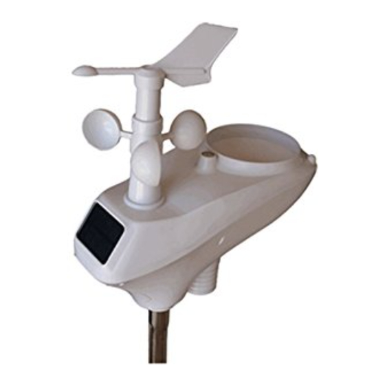
- Page 24 Figure 1 Description Description Wind Vane (measures wind direction) Reset button Wind Speed Sensor (measures wind Thermo-hygrometer Sensor speed) (measures temperature and humidity) Solar collector UV sensor battery compartment Solar Radiation Sensor LED transmission indicator (turns on Rain Collector (self emptying) for 10 seconds on power up, flashes Bubble Level once per 16 seconds)
- Page 25 4.3.2 Install Mounting Pole Reference Figure 3. Remove the mounting pole collar by rotating counter clockwise. Figure 3...
- Page 26 Reference Figure 4. Locate and align the groove on the sensor array and mounting pole. Figure 4...
- Page 27 Reference Figure 5. Turn the mounting pole collar to lock the pole into place by rotating clockwise. Figure 5 4.3.3 Install Batteries Reference Figure 6. Locate the battery door on the bottom of the sensor array. Turn the set screw counter clockwise to open the battery compartment. Insert the 3xAA batteries (not included).
- Page 28 Figure 6...
- Page 29 4.3.4 Mount Weather Station Fasten the mounting pole to your mounting pole with the U-bolt, mounting pole brackets and nuts, as shown in Figure 7. Tighten the mounting pole to your mounting pole with the U-Bolt assembly. Make sure your mounting pole is as far away from the temperature sensor as possible, as shown in Figure 7.
- Page 30 1. Reference Figure . Locate the four wind vane compass rose indicators of N, E, S, W (representing North, East, South and West). Align the compass rose direction upon final installation with compass GPS. Figure 8 2. Reference Figure 98. Make sure the sensor array is completely level upon final installation. Failure to do so will result in inaccurate rain gauge readings.
- Page 31 Put batteries back in and resynchronize with the receiver by powering down and up the receiver with the sensor array about 3meter away. Figure 9 4.4 Indoor Thermo-Hygrometer-Barometer Transmitter The indoor thermometer, hygrometer and barometer measures and displays the indoor temperature, humidity and pressure and transmits this data to the receiver.
- Page 32 Note: The thermo-hygrometer-transmitter transmits directly to the receiver. For best results, place between 2 to 8 meter from the receiver. Note: To avoid permanent damage, please take note of the battery polarity before inserting the batteries. Remove the battery door on the back of the sensor with a Philips screwdriver (there is only one screw, at the bottom of the unit).
- Page 33 communication. 3. Line of Sight Rating. This device is rated at 100meter line of sight (no interference, barriers or walls) but typically you will get 30meter maximum under most real-world installations, which include passing through barriers or walls. 4. Metal Barriers. Radio frequency will not pass through metal barriers such as aluminum siding.
- Page 34 Place the sensor array and indoor thermo-hygrometer transmitter about 1 to 3meter from the receiver and wait several minutes for the remote sensors to synchronize with the receiver. Once synchronized, the Indoor blue LED (Error! Reference source not found., reference 2) and Outdoor blue LED (Error! Reference source not found., reference 3) will be illuminated.
- Page 35 Ref. Description LAN connection (connect to router) Reset button AC Power connection Figure 13 4.6.4 Finding the IP scan tool from your computer 4.6.4.1 Windows PC Users To find the IP scan tool receiver, launch the IP Tools software. The HostIP (your computers IP address) will be displayed.
- Page 36 Figure 15 Select the device on your network and select the Open button to view within your browser. Alternately, you can type the IP address in your web browser address bar (example, Figure 17): Figure 16 Figure 17 You are now communicating directly to the device and can proceed to Section 40. If you cannot access the device, press the reset pinhole on the back of the receiver (reference Figure 13) and wait for the lights to stabilize, and repeat by selecting the Search button again.
- Page 37 4.6.4.2 Mac PC Users Launch the IP tool. The HostIP (your computers IP address) will be displayed. Figure 19 Click the Search button (Figure 20) to find the device on your local area network (Figure 21). Figure 20...
- Page 38 Figure 21 Select the device on your network and click the Open button(Figure 22) to view within your browser. Alternately, you can type the IP address in your web browser address bar.(example, Figure 23) Figure 22 Figure 23 4.6.4.3 Linux Users If you use Linux operating system, download any commercially available IP scan tool, such as AngryIP Scanner and find the MAC address of the device.
- Page 39 Figure 24 Type the IP address you located from the IP Scan Tool into your web browser (example, Figure 5): Figure 25 You are now communicating directly to the device and can proceed to Section 0. 4.6.5 Local Device Network Settings From your web browser, access the device from the IP address obtained in the previous section.
- Page 40 To confirm the changes, select Apply and Reboot. Note: If you incorrectly set the static IP settings and can no longer access the device, press the reset button on the back of the receiver. Figure 186 4.6.6 Weather Network Settings Select the Weather Network tab to program the Weather Network settings.
- Page 41 Figure 197 If you select default remote server as rtupdate.wunderground.com, please follow the below procedure to got the Weather ID and Pass word. 1. Join Wunderground.com® Community. Visit: https://www.wunderground.com/members/signup.asp and sign up with Wunderground.com.
- Page 42 2. Join the Personal Weather Station (PWS) network. Visit: http://www.wunderground.com/personal-weather-station/signup or select More | Register Your PWS from the menu at the top of the WeatherUndeground.com website:...
- Page 43 Enter the Station ID obtained and password you sign up with Wunderground.com. Note: If Wunderground.com® is not updating, make sure the Station ID and Password are correct. The Station ID is all capital letters, and the password is case sensitive. The most common issue is substituting an O for 0 in the Station ID.
- Page 44 Station ID: KAZPHOEN11, not KAZPH0EN11 K = USA station designation AZ = Arizona PHOEN = Phoenix 11= station 11 in Phoenix, AZ 4.6.7 Station Settings Select Apply to confirm any of the changes in this section. 4.6.7.1 Wireless Transmitter Settings 1.
- Page 45 Figure 208 4.6.8 Live Data Select the Live Data tab to view your live data from the weather station. To freeze the live data updates, select the Stop Refresh button. 4.6.8.1 Reset Rain During the installation of your weather station, you may report false rain due to vibration of the tipping mechanism.
- Page 46 Figure 219 4.6.9 Calibration Select the Calibration tab to view your calibration data from the weather station. Select the Apply button to confirm changes.
- Page 47 Calibration of most parameters is not required, with the exception of Relative Pressure, which must be calibrated to sea-level to account for altitude effects. For more information on sea-level pressure calibration, please reference note (3) below. 4.6.9.1 Relative Barometric Pressure Calibration Example The following is an example of calibrating the relative pressure.
- Page 48 Figure 22 Figure 30...
- Page 49 Parameter Type of Default Typical Calibration Source Calibration Temperature Offset Current Value Red Spirit or Mercury Thermometer (1) Humidity Offset Current Value Sling Psychrometer (2) Offset Current Value Calibrated laboratory grade Barometer barometer REL Barometer Offset Current Value Local airport (3) Wind Offset Current Value GPS, Compass (4)
- Page 50 building structure, ground trees). To calibrate temperature, we recommend a mercury or red spirit (fluid) thermometer. Bi- metal (dial) and digital thermometers (from other weather stations) are not a good source and have their own margin of error. Using a local weather station in your area is also a poor source due to changes in location, timing (airport weather stations are only updated once per hour) and possible calibration errors (many official weather stations are not properly installed...
- Page 51 (4) Only use this if you improperly installed the weather station sensor array, and did not point direction reference true north. (5) The default conversion factor based on the wavelength for bright sunlight is 126.7 lux / w/m . This variable can be adjusted by photovoltaic experts based on the light wavelength of interest, but for most weather station owners, is accurate for typical applications, such as calculating evapotransporation...
- Page 52 6. Glossary of Terms Term Definition Absolute Barometric Absolute pressure is the measured atmospheric pressure and is a Pressure function of altitude, and to a lesser extent, changes in weather conditions. Absolute pressure is not corrected to sea-level conditions. Refer to Relative Barometric Pressure.
- Page 53 Term Definition (inHg) 1 inch of mercury = 33.86 millibars Rain Gauge A rain gauge is a device that measures liquid precipitation (rain), as opposed to solid precipitation (snow gauge) over a set period of time. All digital rain gauges are self emptying or self dumping (also referred to as tipping rain gauge).
- Page 54 7.2 Measurement Specifications The following table provides the specifications for the measured parameters. Measurement Range Accuracy Resolution Indoor Temperature 0 to 60 °C ± 1 °C 0.1 °C Outdoor -40 to 65 °C sensor ± 1 °C 0.1 °C Temperature -5 to 60 °C battery range (alkaline) Indoor Humidity...
- Page 55 Step 5: Remove the cotton swab and flush with water to remove any remaining dirt. Step 6: Re-enter the rain totals recorded in Step 1. Figure 23 2. Clean the solar radiation sensor every 3 months with water and towel. 3.
- Page 56 Figure 25...
- Page 57 2. Troubleshooting Guide Problem Solution Wireless remote The maximum line of sight communication range is about 100m. (thermo- Move the sensor assembly closer to the receiver. hygrometer) not reporting in to Install a fresh set of batteries in the remote sensor(s). Receiver.
- Page 58 Problem Solution Wireless remote The maximum line of sight communication range is about 100m. (thermo- Move the sensor assembly closer to the receiver. hygrometer) not reporting in to Install a fresh set of batteries in the remote sensor(s). Receiver. Make sure the remote sensors are not transmitting through solid metal (acts as an RF shield), or earth barrier (down a hill).
- Page 59 Problem Solution Wireless remote The maximum line of sight communication range is about 100m. (thermo- Move the sensor assembly closer to the receiver. hygrometer) not reporting in to Install a fresh set of batteries in the remote sensor(s). Receiver. Make sure the remote sensors are not transmitting through solid metal (acts as an RF shield), or earth barrier (down a hill).
- Page 60 3. Liability Disclaimer Please help in the preservation of the environment and return used batteries to an authorized depot. The electrical and electronic wastes contain hazardous substances. Disposal of electronic waste in wild country and/or in unauthorized grounds strongly damages the environment. Reading the “User manual”...
Need help?
Do you have a question about the IP Observer WH2600 SE and is the answer not in the manual?
Questions and answers