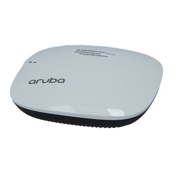
Table of Contents
Advertisement
Quick Links
Aruba 207 Series
Wireless Access Point
Installation Guide
a Hewlett Packard
Enterprise company
Package Contents
(I)AP-207 access point
9/16" and 15/16" Ceiling Rail Adapter (spare: AP-220-MNT-
C1)
Regulatory Compliance and Safety Information Guide
Instant Quick Start Guide (for IAP-207 only)
Professional Install Guide (for IAP-207 only)
Installation Guide (this document).
This device must be professionally installed and
serviced by a trained ACMP or similar Aruba-certified
technician. Aruba access points are classified as radio
transmission devices, and are subject to government
regulations of the host country. The network
administrator(s) is/are responsible for ensuring that
configuration and operation of this equipment is in
compliance with their country's regulations. For
complete list of approved channels in your country,
refer to the Aruba Downloadable Regulatory Table at
support.arubanetworks.com.
Access points are radio transmission devices and are
subject to governmental regulation. Network
administrators responsible for the configuration and
operation of access points must comply with local
broadcast regulations. Specifically, access points must
use channel assignments appropriate to the location in
which the access point will be used.
207 Series Hardware Overview
LEDs
The 207 Series access points have two LEDs that indicate the
system and radio status of the device. These two LEDs can be
configured via ArubaOS (for AP-207) or Aruba Instant (for
IAP-207) software into three separate modes:
Normal mode (by default): See
Both LEDs off
0511875-02 |
April 2016
Table 1
Blink mode: Both LEDs blink green (synchronized)
Figure 1
LEDs
System Status
Radio Status
Table 1
207 Series LEDs Status in Normal Mode
LED
Color/State
Meaning
System
Off
Device powered off
Status
(Left)
Green-
Device booting, not ready for use
Blinking
Green- Solid
Device ready for use, no restrictions
Green-
Device ready for use, uplink negotiated
Flashing
in sub optimal speed (<1Gbps)
Red- Solid
System error condition
Radio
Off
Device powered off, or both radios
Status
disabled
(Right)
Green- Solid
Both radios enabled in access mode
Green-
One radio enabled in access mode
Blinking
Amber- Solid
Both radios enabled in monitor mode
Amber-
One radio enabled in monitor mode
Blinking
Alternating
Figure 2
Back Panel
Ethernet Port
12V
1A
ENET
56V
350mA
CONSOLE
Console Port
The serial console port is located at the back of the (I)AP-207
and is a 4-pin connector covered by a dust cover. An optional
serial adapter cable (AP-CBL-SER) is sold separately to
connect the (I)AP to a serial terminal or a laptop for direct
local management.
Ethernet Port
The 207 Series access points are equipped with one 10/100/
1000Base-T (RJ-45) auto-sensing, MDI/MDX Ethernet port
Green: one radio in access mode
Amber: one radio in monitor mode
DC Power Socket
Console Port
Reset Button
Kensington
Lock Slot
1
Advertisement
Table of Contents

Subscribe to Our Youtube Channel
Summary of Contents for Aruba 207 Series
-
Page 1: Wireless Access Point
LEDs and is a 4-pin connector covered by a dust cover. An optional The 207 Series access points have two LEDs that indicate the serial adapter cable (AP-CBL-SER) is sold separately to system and radio status of the device. These two LEDs can be... - Page 2 (ENET0) for wired network connectivity. This port supports The 207 Series access points ship with two ceiling rail IEEE 802.3af Power over Ethernet (PoE), as a standard adapters for 9/16” and 15/16” ceiling rails. Additional ceiling defined Powered Device (PD) from a Power Sourcing...


Need help?
Do you have a question about the 207 Series and is the answer not in the manual?
Questions and answers