
Related Manuals for Allen-Bradley PanelView Plus 2711P


Summary of Contents for Allen-Bradley PanelView Plus 2711P
- Page 1 PanelView Plus Operator Terminals 2711P (400, 600, 700, 1000, 1250, 1500) User Manual AB Drives...
-
Page 2: Important User Information
Important User Information Solid state equipment has operational characteristics differing from those of electromechanical equipment. Safety Guidelines for the Application, Installation and Maintenance of Solid State Controls (Publication SGI-1.1 available from your local Rockwell Automation sales office or online at http://www.ab.com/manuals/gi) describes some important differences between solid state equipment and hard-wired electromechanical devices. -
Page 3: Table Of Contents
Table of Contents Important User Information ......1-2 Preface Objectives....... . . Preface-i Packing List . - Page 4 Table of Contents Diagnostic Setup ....... . 4-15 File Management....... . 4-16 Display.
- Page 5 Table of Contents Chapter 8 Troubleshooting and Maintenance Chapter Objectives ......8-1 LED Indicators .
- Page 6 Table of Contents Publication 2711P-UM001B-EN-P...
-
Page 7: Objectives
Preface Objectives This preface provides information on the contents of this manual including: • Contents of manual • Intended audience • European Union Directive Compliance • Rockwell Automation Support Packing List The following items are shipped with an assembled PanelView™ Plus terminal: •... -
Page 8: Manual Contents
Preface Manual Contents Chapter Title Description Overview Provides overview of the PanelView Plus terminals including features and product components. Installation Gives Instructions on how to install the PanelView Plus terminal in a panel or enclosure. Applying Power Describes how to apply power and reset the PanelView Plus terminal. -
Page 9: Related Publications
Programmable Controllers, Part 2 - Equipment Requirements and Tests. For specific information required by EN 61131-2, see the appropriate sections in this publication, as well as the Allen-Bradley publication Industrial Automation Wiring and Grounding Guidelines For Noise Immunity, publication 1770-4.1. -
Page 10: Rockwell Automation Support
Preface Rockwell Automation Rockwell Automation provides technical information on the web to assist you in using our products. At http://support.rockwellautomation.com, you can Support find technical manuals, a knowledge base of FAQs, technical and application notes, sample code and links to software service packs, and a MySupport feature that you can customize to make the best use of these tools. -
Page 11: Chapter 1 Chapter Objectives
Chapter Overview Chapter Objectives This chapter gives an overview of the PanelView Plus terminal line including: • software support • PanelView Plus 400 - 600 terminal features • PanelView Plus 700 - 1500 terminal features • catalog number configuration • product components Software Support RSView Machine Edition runtime is included with all PanelView Plus terminals. -
Page 12: Panelview Plus 400 - 600 Features
Overview PanelView Plus 400 - 600 This section gives an overview of the PanelView Plus 400 and 600 terminals including: Features • hardware features • base configured units • communication modules • AC or DC power supply • displays Hardware Features The PanelView Plus 400 and 600 terminals are operator interface devices. - Page 13 Overview Base Configured Units The base configured unit of the PanelView Plus 400 and 600 terminals terminal are available in two versions: • Base unit with RS-232 only and (1) USB port • Base unit with RS-232, 10/100BaseT Ethernet, (1) USB port and a network interface for communication module RS-232 Only AC or DC Power Input...
- Page 14 Overview Communication Modules You can attach a separate communication module to the base configured unit of the PanelView Plus with a network interface to increase your communications capability. • DH-485 • DH+ • Remote I/O (single rack) • Isolated RS-232 The Communication Module installs easily on the back of the unit.
- Page 15 Overview Displays and Input Options PanelView Plus 400 and 600 terminals are available with the following display and operator input options: • 400 terminals: 3.7 inch grayscale (320 x 240) graphics display with keypad • 600 terminals: 5.5 inch color or grayscale (320 x 240) graphics display with keypad, touch screen, or keypad &...
- Page 16 Replaceable legends are available for the 600 terminals allowing for custom function key labels. ID Label Allen-Bradley ID label. The ID label is replaceable allowing for custom product identification. Numeric Keypad 0-9, ., -, Backspace, Enter, Left and Right...
-
Page 17: Panelview Plus 700 - 1500 Features
Overview PanelView Plus 700 - 1500 This section gives an overview of the PanelView Plus 700, 1000, 1250, 1500 terminals including: Features • hardware features • modular components • base configured unit • communication modules • remote AC power supply •... - Page 18 Overview Modular Components The PanelView Plus 700 - 1500 terminals use modular components allowing for flexible configuration, installation, and upgrades. Items can be ordered as separate components or factory assembled per your configuration. Communication Module Logic Module Display Module Base Configured Unit The base configured unit of the PanelView Plus terminal consists of: •...
- Page 19 Overview Communication Modules You can attach a separate Communication Module to the base configured unit of the PanelView Plus terminal to increase your communications capability. The Communication Modules install easily on top of the Logic Module on the back of the unit. Communication Module Remote AC Power Supply The Logic Module provides a DC power input.
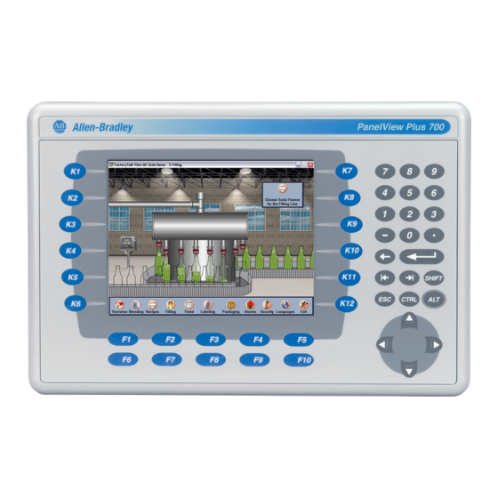
- Page 20 1-10 Overview Display Modules PanelView Plus 700 - 1500 terminals offer a range of TFT color graphic displays with either keypad, touch screen, or keypad & touch support. • 700 (6.5 inch) • 1000 (10.4 inch) • 1250 (12.1 inch) •...
- Page 21 1250 (F1-F20, K1-K20) custom function key labels. 1500 (F1-F20, K1-K20) Label Allen-Bradley ID label. The ID label is replaceable allowing for custom product identification. IrDA Port For data or application transfers. Numeric Keypad 0-9, ., -, Backspace, Enter, Left and Right...
-
Page 22: Catalog Number Configuration
1-12 Overview Catalog Number The following table shows the catalog number configuration for PanelView Plus terminals. Configuration Input Display Display Type Communications Power Memory Label Type Size Flash/RAM 2711P- K = Keypad 4 = 3.7 inch C = Color PanelView Plus 400 and 600 Terminals A = AC 1= 32 MB/64 MB Blank =AB Label... - Page 23 Overview 1-13 Logic Module (700 - 1500 only) Cat. No. Description 2711P-RP Logic Module without memory Remote AC Power Supply (700 - 1500 only) Cat. No. Description 2711P-RSACDIN AC to DC DIN Rail Power Supply, 85…265V ac, 47…63 Hz Internal Compact Flash Cards (700 - 1500 only) Cat.
- Page 24 1-14 Overview Communication Modules Terminal Type Cat. No. Description 2711P-RN1 Single Rack Remote I/O Communication Module 2711P-RN3 DH-485 Communication Module 400 - 600 2711P-RN8 DH+ Communication Module 2711P-RN22C RS-232 Isolated Communication Module 700 - 1500 2711P-RN6 DH+/DH-485/Remote I/O Communication Module 2711P-RN15S ControlNet Communication Module Compact Flash Cards (Blank)
- Page 25 Overview 1-15 Protective Antiglare Overlays Cat. No. Description 2711P-RGK4 Antiglare Overlay for PanelView Plus 400 Keypad Terminal 2711P-RGK6 Antiglare Overlay for PanelView Plus 600 Keypad or Keypad/Touch Terminal 2711P-RGT6 Antiglare Overlay for PanelView Plus 600 Touch Terminal 2711P-RGK7 Antiglare Overlay for PanelView Plus 700 Keypad or Keypad/Touch Terminal 2711P-RGT7 Antiglare Overlay for PanelView Plus 700 Touch Terminal 2711P-RGK10...
- Page 26 1-16 Overview Cables Cat. No. Description 2711-NC13 RS-232 Operating/Programming Cable (9-pin D-Shell to 9-pin D-Shell), 5 m (16.4 ft) 2711-NC14 RS-232 Operating/Programming Cable (9-pin D-Shell to 9-pin D-Shell), 10 m (32.7 ft) 2711-NC17 Remote RS-232 Serial Cable (9-Pin D-Shell to 9-Pin D-Shell) 2711-NC21 RS-232 Operating Cable (9-pin D-Shell to 8-pin Mini DIN), 5 m (16.4 ft) 2711-NC22...
-
Page 27: Chapter 2 Chapter Objectives
Chapter Installation Chapter Objectives This chapter provides instructions on how to install the PanelView Plus terminals. It provides information on: • hazardous locations • environment • enclosures • clearances • required tools • cutout dimensions • mounting dimensions • 400 - 600 panel installation •... - Page 28 Installation PanelView Plus 400/600 USB Port The PanelView Plus 400/600 Terminals contain a single USB (Universal Serial Bus) port which complies with hazardous location environments. This section details the field wiring compliance requirements and is provided in accordance with the National Electrical Code, article 500.
-
Page 29: Environmental Considerations
Installation Application Information Per the National Electrical Code, the circuit parameters of associated field wired apparatus for use in hazardous locations shall be coordinated with the host product such that their combination remains nonincendive. The PanelView Plus 400/600 and the USB peripheral device shall be treated in this manner. -
Page 30: Clearances
Installation Clearances You must allow adequate clearances around the terminal, inside the enclosure, for adequate ventilation. Consider heat produced by other devices in the enclosure. The ambient temperature around the terminals must be between 0…55 °C (32…131 ºF). Clearance 400 - 600 Terminals 700 - 1500 Terminals 51 mm (2 in) 51 mm (2 in) -
Page 31: Mounting Dimensions
Installation Mounting Dimensions This section provides mounting dimensions for the entire line of PanelView Plus terminals. All measurements are in mm (inches). PanelView Plus 400 (6.0) 185 (7.28) 3.54) (2.35) 71 (2.81) 154 (6.08) AB Drives Publication 2711P-UM001B-EN-P... - Page 32 Installation PanelView Plus 600 600 Keypad or Keypad & Touch Terminal (6.58) (2.68) (3.86) 71 (2.81) 268 (10.47) 154 (6.08) 600 Touch Terminal (2.68) (6.0) (3.86) 71 (2.81) 154 (6.08) 185 (7.28) Publication 2711P-UM001B-EN-P...
- Page 33 Installation PanelView Plus 700 The depth dimensions are shown for: • base configured unit (Display Module and Logic Module) • base configured unit with Communication Module 700 Keypad or Keypad & Terminal a 55 (2.18) Display to Logic Module b 83 (3.27) Display to Communication Module (7.58) (11.40) 700 Touch Screen Terminal...
- Page 34 Installation PanelView Plus 1000 The depth dimensions are shown for: • base configured unit (Display Module and Logic Module) • base configured unit with Communication Module 1000 Keypad or Keypad & Touch Terminal a 55 (2.18) Display to Logic Module b 83 (3.27) Display to Communication Module (9.77) (15.72)
- Page 35 Installation PanelView Plus 1250 The depth dimensions are shown for: • base configured unit (Display Module and Logic Module) • base configured unit with Communication Module 1250 Keypad or Keypad & Touch Terminal a 55 (2.18) Display to Logic Module (11.12) b 83 (3.27) Display to Communication Module (16.36)
- Page 36 2-10 Installation PanelView Plus 1500 The depth dimensions are shown for: • base configured unit (Display Module and Logic Module) • base configured unit with Communication Module 1500 Keypad or Keypad & Touch Terminal (12.97) a 65 (2.55) Display to Logic Module b 93 (3.65) Display to Communication Module (18.46) 1500 Touch Screen Terminal...
-
Page 37: 400 - 600 Panel Installation
Installation 2-11 400 - 600 Panel Installation The PanelView Plus 400 and 600 terminals are installed in the same manner using mounting levers. The number of levers used (4 or 6) varies by terminal type. The mounting levers are shipped with each terminal. - Page 38 4.19 - 4.75 mm (0.165 - 0.187 in) Follow instructions above to provide a proper ATTENTION seal and to prevent potential damage to the terminal. Allen-Bradley assumes no responsibility for water or chemical damage to the terminal or other equipment within the enclosure because of improper installation.
-
Page 39: 700 - 1500 Panel Installation
Installation 2-13 700 - 1500 Panel Installation The PanelView Plus 700 - 1500 terminals are installed in the same manner using clips for mounting. The number of clips used (4, 6 or 8) varies by terminal type. The mounting clips are shipped with each terminal. - Page 40 ATTENTION of .90 - 1.1 N•m (8 - 10 in-lb) to provide a proper seal and to prevent potential damage to the terminal. Allen-Bradley assumes no responsibility for water or chemical damage to the terminal or other equipment within the enclosure because of improper installation.
-
Page 41: Chapter 3 Chapter Objectives
Chapter Applying Power Chapter Objectives This chapter provides information on: • wiring and safety guidelines • removing and installing power terminal block • connecting DC power • connecting AC power • resetting the terminal • startup sequence Wiring and Safety Use publication NFPA 70E, Electrical Safety Requirements for Employee Workplaces when wiring the PanelView Plus terminals. -
Page 42: Installing And Removing Power Terminal Block
Applying Power Installing and Removing You can remove and re-install the DC or AC power terminal block for ease of installation, wiring, and maintenance. The terminal block is Power Terminal Block pre-installed when shipped. Explosion Hazard WARNING • Substitution of components may impair suitability for hazardous locations. -
Page 43: Connecting Dc Power
Applying Power 700 - 1500 Terminals To remove terminal block: 1. Remove the two screws that secure the terminal block. 2. Gently pull the terminal block away from the connector. To install terminal block: 1. Re-attach the terminal block to the connector until seated. 2. - Page 44 Applying Power For DC powered units, use a Class 2/SELV (Safety ATTENTION Extra-Low Voltage) isolated and ungrounded power supply as input power to the PanelView Plus terminal. This power source provides protection so that under nominal and single fault conditions, the voltage between conductors and between conductors and Functional Earth/Protective Earth does not exceed a safe value.
-
Page 45: Connecting Ac Power
Applying Power Connecting AC Power The PanelView Plus 400 - 600 terminals are available with an integrated AC power supply. A DIN Rail mounted AC power supply is available as a separate catalog number for the PanelView Plus 700 - 1500 terminals. -
Page 46: Resetting The Terminal
Applying Power To connect AC power: 1. Secure the AC power wires to the terminal block screws. 2. Secure the Earth Ground wire to the appropriate terminal block screw. L1 L2N Protective L2/N Earth Ground 3. Apply power to the terminal. Resetting the Terminal 400 - 600 Terminals The PanelView Plus 400 and 600 terminals have a Reset switch on the... - Page 47 Applying Power 700 - 1500 Terminals The PanelView Plus 700 - 1500 terminals have both a Reset switch and a Default switch on the side of the logic module. Default Reset Reset Use the RESET switch to restart the terminal without having to disconnect and reapply power.
-
Page 48: Startup Sequence
Applying Power Startup Sequence After a reset, the PanelView Plus performs a series of startup tests and then either: • runs the .MER application currently loaded in the terminal • enters PanelView Plus configuration mode The action that occurs depends on what startup options are configured for your PanelView Plus terminal. -
Page 49: Chapter 4 Chapter Objectives
Chapter Using Configuration Mode Chapter Objectives This chapter shows how to use the configuration screens of your PanelView Plus terminal to: • perform data entry and navigation • load an ME application • run an ME application • modify application settings •... - Page 50 Using Configuration Mode Main Screen Button Description Load Application (F1) Opens another screen where you can select an application to load. Once loaded, the application name will appear under Current Application. Run Application (F2) Runs the .MER application displayed under Current Application. An application must be loaded before you can run it.
- Page 51 Using Configuration Mode Input Panel Many screens have buttons that access fields where you must enter/edit data. When you press the button or function key, the Input Panel opens ready for you to input data. If the field is restricted to a numeric value, only the 0-9 keys will be enabled.
-
Page 52: Loading An Me Application
Using Configuration Mode Loading an ME Application To load an RSView ME .MER application, select the Load Application button on the main screen: List of .mer applications stored in the compact Moves flash of the terminal. highlight up Moves highlight down 1. -
Page 53: Running An Application
Using Configuration Mode Running an Application To run the currently loaded application, select the Run Application button on the main Configuration Mode screen. An application must be loaded, before you can run it. Log files generated by the application may be deleted if this option was selected on the main screen or enabled as a Startup Option under Terminal Settings. -
Page 54: Networks And Communications
Using Configuration Mode Terminal Setting Description Startup Options Specifies whether the terminal starts up in configure or run mode. Also lets you enable/disable tests to run on the terminal at startup. System Event Log Displays a list of system events currently logged by the terminal. - Page 55 Using Configuration Mode RSLinx Enterprise Communications Terminal Settings Networks and Communications The RSLinx Enterprise Communications screen shows a treeview of installed communication cards and network configurations. You can: RSLinx Enterprise Communications • edit/view the driver settings for the communication protocol used by your .MER application.
- Page 56 Using Configuration Mode To edit communication settings: 1. From the RSLinx Configuration Screen, select the communication card installed on your terminal. 2. Select the Driver Settings button. A properties screen opens showing the current communication settings for the driver. 3. To modify a setting, select the setting and then the Edit button. The Input Panel opens showing the current setting.
- Page 57 Using Configuration Mode DHPlus Properties The DHPlus Properties screen lets you view or modify settings for a PanelView Plus connected to a DHPlus network. Field Description Valid Values Identifies the communication card if multiple 0 - 3 Jumper ID cards are installed on terminal. Station Number The unique address of the PanelView Plus on 0 - 77 (octal)
- Page 58 4-10 Using Configuration Mode ControlNet Properties The ControlNet Properties screen configures ControlNet communication settings for the PanelView Plus terminal on a ControlNet network. Field Description Valid Values Device ID Unique address of the PanelView Plus 1 - 99 terminal on the ControlNet network. Serial Properties The Serial Properties screen configures settings for serial communications (using the RS-232 serial port) on the PanelView Plus...
- Page 59 Using Configuration Mode 4-11 Network Connections Terminal Settings Networks and Communications The Network Connections screen lets you configure the following for the PanelView Plus terminal: Network Connections • Device Name • Network Adapters • Network Identification Device Name Terminal Settings Networks and Communications The Device Name screen identifies the PanelView Plus terminal to other computers on the network.
- Page 60 4-12 Using Configuration Mode Network Adapters Terminal Settings Networks and Communications The Network Adapters screen configures driver settings for all network adapters installed on the terminal. The only network adapter Network Connections on the PanelView Plus terminal is the (IntelR) Fast Ethernet Controller. Network Adapters Press the Name Servers button and/or IP Address button to access driver settings.
- Page 61 Using Configuration Mode 4-13 IP Address The IP Address screen identifies the IP address of the selected network adapter. If the network the PanelView Plus is connected to does not automatically assign an IP address, you can assign the address in this screen. Field Description Valid Values...
- Page 62 4-14 Using Configuration Mode Network Identification Terminal Settings Networks and Communications The Network Identification screen configures settings that enable the PanelView Plus terminal to gain access to network resources. You can Network Connections enter a user name, password and domain (provided by your network administrator).
-
Page 63: Diagnostic Setup
Using Configuration Mode 4-15 Diagnostic Setup The Diagnostic Setup screen configures diagnostics for the current computer. The screen shows a treeview of possible diagnostic nodes. Terminal Settings To access the Remote Log Setup or Message Diagnostic Setup Routing, select the node and then the Edit button. -
Page 64: File Management
4-16 Using Configuration Mode File Management The File Management screen lets you access screens to: • Delete Files • Copy Files Delete Files Terminal Settings From the Delete Files screen you can select options to: File Management • Delete Applications - deletes an .MER application file from a Delete Files storage location. - Page 65 Using Configuration Mode 4-17 Delete Log Files Select this option to delete any data log files, alarm history files and alarm status files in the System Default location on the PanelView Plus terminal. You will be asked to confirm the operation. Do you want to delete all of the RSView ME Station Log Files? Select Yes or No.
- Page 66 4-18 Using Configuration Mode 2. Select the Destination button on the same screen to open the following screen. 3. Select the Destination button to select the storage location where you want to copy the application or font file to. • Internal Storage - the Internal Compact Flash in the PanelView Plus terminal.
-
Page 67: Display
Using Configuration Mode 4-19 Display The Display screen lets you open screens to access: • Display Contrast • Display Intensity • Display Temperature • Screen Saver Display Contrast Terminal Settings Display The Display Contrast screen lets you view and modify the current contrast setting of the PanelView Plus 400 - 600 grayscale displays. - Page 68 4-20 Using Configuration Mode Display Intensity Terminal Settings Display The Display Intensity screen lets you view or modify the current intensity of the backlight. The default intensity is 100%. When you Display Intensity change the intensity, the terminal temporarily changes to that intensity.
-
Page 69: Font Linking
Using Configuration Mode 4-21 Screen Saver Terminal Settings The Screen Saver screen lets you: Display • disable the screen saver Screen Saver • enable the screen saver after the selected idle time • adjust the brightness intensity of the screen saver Select Up or Down Cursor button to increase or decrease... -
Page 70: Input Devices
4-22 Using Configuration Mode Input Devices The Input Devices screen lets you access screens to view and modify settings for: • Keyboard • Keypad • Mouse • Touch Screen Keyboard and Keypad Setup The Keyboard and Keypad screen opens these screens: •... - Page 71 Using Configuration Mode 4-23 Key Settings for PanelView Plus Keypad The Keypad Settings screen enables/disables Single Key Mode option which is used to restrict multiple or simultaneous key presses. Field Description Valid Values Single Key Mode Enables or disables Single Key Mode. Enabled Enabled with Abort If enabled, any programmable key that is...
- Page 72 4-24 Using Configuration Mode Touch Screen Terminal Settings Input Devices The Touch Screen lets you access the following screens: • Calibration Touch Screen • Cursor • Double-Tap Sensitivity Touch Screen Calibration This screen calibrates the touch screen of the PanelView Plus terminal. Touch the center of the target (+) each of the 4 times it appears.
- Page 73 Using Configuration Mode 4-25 Double-Tap Sensitivity This screen lets you set and test the sensitivity for both speed and physical distance between touch screen presses. • The Set button sets the sensitivity of touch screen presses. • The Test button tests the sensitivity of touch screen presses. If you double-tap the test button with the time set using the Set button, the Test button will reverse it’s foreground and background colors.
-
Page 74: Print Setup
4-26 Using Configuration Mode Print Setup The Print Setup screen lets you access screens to configure print options for: • Displays • Alarms • Diagnostic messages. Display, Alarm, and Diagnostic Print Setup Terminal Settings Print Setup The general setup for printing displays, alarm messages and diagnostics messages from an RSView .MER application is the same. - Page 75 Using Configuration Mode 4-27 Advanced Settings for Diagnostic Messages and Alarm Messages The following screen configures when to print diagnostic or alarm messages that are sent to the Network or USB port. To configure how messages are queued for printing, select the Print Messages After button and set one of the following options: •...
-
Page 76: Startup Options
4-28 Using Configuration Mode Startup Options The Startup Options screen accesses the following screens to modify: • RSView ME Station Startup • Startup Tests Terminal Settings RSView ME Station Startup Startup Options The RSView Machine Station Startup screen specifies what action the PanelView Plus terminal takes on startup: RSView ME Station Startup •... - Page 77 Using Configuration Mode 4-29 Configuration Mode The Configuration Mode Options screen specifies whether the PanelView Plus will boot up in Configure Mode: • with the current application loaded. • with the communication configuration of the current application or the terminal’s RSLinx communication configuration. If you select Yes to replace the terminal’s communication configuration with that of the application, any changes made to the device addresses or driver properties in the RSLinx...
- Page 78 4-30 Using Configuration Mode Startup Tests Terminal Settings Startup Options The PanelView Plus can run extended tests on startup. The Startup Tests screen provides access to these screens: Startup Tests • Startup Tests Settings • Repeat Count Startup Tests apply only to PanelView Plus 700 - IMPORTANT 1500 terminals.
- Page 79 Using Configuration Mode 4-31 Startup Tests Settings From the Startup Tests Settings screen, you can: • enable extended diagnostics to run on the terminal at startup • disable extended diagnostics at startup • specify how many times to repeat the selected tests that are run on the terminal during startup.
-
Page 80: System Event Log
4-32 Using Configuration Mode System Event Log The System Event Log screen displays a list of system events currently logged by the PanelView Plus terminal. Terminal Settings System Event Log • To display System Event Log Details for a specific event, select an event and then select the More Details button. -
Page 81: System Information
Using Configuration Mode 4-33 System Information The System Information screen lets you access: • RSView ME Station information • Terminal Information Terminal Information Terminal Settings System Information The Terminal Information screen displays the following details for the PanelView Plus terminal: •... - Page 82 4-34 Using Configuration Mode Memory Allocation The Memory Allocation screen displays: • amount of allocated storage or program memory • amount of storage or program memory currently in use You can modify the allocation of storage or program memory. Press the Up or Down button to increase/decrease the memory allocation.
- Page 83 Using Configuration Mode 4-35 RSView ME Station Information Terminal Settings System Information The About RSView ME Station screen provides access to: • RSView ME Station firmware number About RSView ME Station • Rockwell Technical Support information x.xx.xx.xx AB Drives Publication 2711P-UM001B-EN-P...
-
Page 84: Time/Date/Regional Settings
4-36 Using Configuration Mode Time/Date/Regional The Time/Date/Regional Settings screen lets you access the following screens to set: Settings • date • regional settings • time • time zone Date Terminal Settings Time/Date/Regional Settings The Date screen shows and configures the current date in separate Year, Month and Day fields. - Page 85 Using Configuration Mode 4-37 Time Terminal Settings Time/Date/Regional Settings The Time screen shows and configures the current time in 24-hour format in separate Hour, Minute and Second fields. Time Field Description Valid Values Hour The current hour in 24-hour format. 0 - 23 Minute The current minute in 24-hour format.
- Page 86 4-38 Using Configuration Mode Time Zone Terminal Settings Time/Date/Regional Settings The Time Zone screen shows the current time zone that is installed on the PanelView Plus terminal. Time zones are installed as a part of the Time Zone operating system. Changing the time zone adjusts the current time and date to match the new time zone.
- Page 87 Using Configuration Mode 4-39 Regional Settings Terminal Settings The Regional Settings screen allows you to access these screens: Time/Date/Regional Settings • Language Regional Settings • Numeric Format • Long Date Format • Short Date Format • Time Format The current language is shown at the bottom of the Regional Settings screen.
- Page 88 4-40 Using Configuration Mode Time Format Terminal Settings The Time Format screen configures the time format for the current Time/Date/Regional Settings language. A sample of the current time is shown using the currently selected format. Regional Settings Time Format Field Description Example h:mm:ss tt (default)
- Page 89 Using Configuration Mode 4-41 Short Date Format Terminal Settings The Short Date Format screen configures the short date format used Time/Date/Regional Settings by the current language. A sample of the current date is shown using Regional Settings the currently selected short date format. Short Date Format Field Short Date Formats...
- Page 90 4-42 Using Configuration Mode Long Date Format Terminal Settings The Long Date Format screen configures the long date format used by Time/Date/Regional Settings the current language. A sample of the current date is shown using the Regional Settings currently selected long date format. Long Date Format Field Short Date Formats...
-
Page 91: Chapter 5 Chapter Objectives
Chapter Installing and Replacing Components Chapter Objectives This chapter shows how to install, replace or upgrade various components of the PanelView Plus terminals. Most sections (except for Communication Module, Product ID labels, Keypad Legend Inserts, and the External Compact Flash Card) apply only to the 700 - 1500 terminals. -
Page 92: Installing Ram And Internal Compact Flash
Installing and Replacing Components Installing RAM and Internal The Logic Module (2711P-RP) of the PanelView Plus terminal does not contain RAM (2711P-RRxxx) or Internal Compact Flash (2711P-RWx) Compact Flash when ordered as a separate component. You must install the RAM and 700 - 1500 Terminals Only Internal Compact Flash before attaching the Logic Module to the Display Module. -
Page 93: Installing And Replacing The Logic Module
Installing and Replacing Components Installing and Replacing This section shows how to install and replace the Logic Module (2711P-RP) of the PanelView Plus terminal. If the Display Module and the Logic Module Logic Module are ordered as separate components, attach the Logic 700 - 1500 Terminals Only Module to the Display Module before panel installation. - Page 94 Installing and Replacing Components To replace the Logic Module: Before replacing the Logic Module, you must remove the Communication Module (if attached). You will also need to remove the Internal RAM and Compact Flash from the Logic Module to reuse in the new Logic Module.
-
Page 95: Installing/Replacing A Communication Module
Installing and Replacing Components Installing/Replacing a This section shows how to install and replace a Communication Module on the PanelView Plus terminal. The Communication Module Communication Module installs over the Logic Module. The Communication Modules are available as separate catalog numbers for specific communication protocols. - Page 96 Installing and Replacing Components 4. Position the Communication Module over the Logic Module so that the connectors on bottom of module align with connectors on Logic Module. 5. To prevent Electrostatic Discharge (ESD) between the modules, allow the Communication Module to touch the Logic Module before making connection.
- Page 97 Installing and Replacing Components Installation for 400 -600 Terminals To install a communication module: 1. Disconnect power from the terminal. 2. Set the terminal, display side down, on a clean, flat, stable surface. 3. Remove the label covering the connectors on the base unit of the terminal.
- Page 98 Installing and Replacing Components To replace a Communication module: 1. Disconnect power from the terminal. 2. Disconnect communication cables from the Communication Module. 3. Loosen the 3 screws that secure the Communication Module to the terminal. 4. Carefully lift the Communication Module away from the terminal and set aside.
-
Page 99: Replacing The Display Module
Installing and Replacing Components Replacing the Display This sections shows how to replace the Display Module (2711P-RDxxxx). It is necessary to remove the Communication Module Module from the Logic Module to perform this operation. 700 - 1500 Terminals Only Communication Module Logic Module Display Module... - Page 100 5-10 Installing and Replacing Components 7. Position the new Logic Module over the new Display Module so that the connectors align. 8. Push down on the Logic Module until firmly seated. 9. Tighten the 6 captive screws that secure the Logic Module to the Display Module to a torque of .68 N•m 6-8 in-lb).
-
Page 101: Replacing The Battery
Installing and Replacing Components 5-11 Replacing the Battery The lithium battery (2711P-RY2032) is used by the real-time clock and static RAM; it is not used for application backup or retention. The 700 - 1500 Terminals Only clock module has a life expectancy of 2 years without power. When you connect or disconnect the battery an WARNING electrical arc can occur. - Page 102 5-12 Installing and Replacing Components 5. Carefully lift the Logic Module away from the terminal and flip over to expose the circuit board. Wear a properly ground ESD wristband IMPORTANT before touching any of the electronic components in the Logic Module. 6.
-
Page 103: Replacing Bezel
Installing and Replacing Components 5-13 Replacing Bezel Removing Display Module Bezel It is not necessary to remove the Logic Module or Communication 700 - 1500 Terminals Only Module before removing the bezel, except for the PanelView Plus 700. 1. Disconnect power from the terminal. 2. - Page 104 5-14 Installing and Replacing Components 6. Lift the back of the Display Module away from the bezel. Work on a clean, flat, stable surface to protect the display from debris, scratches and damage. Display Module Bezel 7. Detach all connectors (maximum of 3). The number of connectors varies by model.
-
Page 105: Replacing Backlight
Installing and Replacing Components 5-15 Replacing Backlight This section shows how to replace the backlight for the 700, 1000, and 1250 models. The 1500 does not have a replaceable backlight. 700 - 1500 Terminals Only 1. Disconnect power from the terminal. 2. - Page 106 5-16 Installing and Replacing Components 5. Detach the Backlight Connector from the circuit board. The 1250 has two Backlight Connectors. Backlight Connector For PanelView Plus 700/1000 Work on a clean, flat, stable surface to protect the display from debris, scratches and damage. 6.
- Page 107 Installing and Replacing Components 5-17 For PanelView Plus 1250 (has 2 Backlights) Work on a clean, flat, stable surface to protect the display from debris, scratches and damage. 8. Remove the 2 screws that secure each of the two backlights and then remove the backlights.
-
Page 108: Installing The Remote Ac Power Supply
If you ordered a PanelView Plus terminal with a label, you can remove it and attach your own label. Label 1. Remove the Allen-Bradley label using your fingers or a tweezers. 2. Clean area with damp cloth and isopropyl alcohol. 3. Remove adhesive backing of OEM label and affix over area where Allen-Bradley label was located. -
Page 109: Installing Keypad Legend Inserts
Installing and Replacing Components 5-19 Installing Keypad Legend This section shows how to replace the legend inserts in the PanelView Plus keypad terminals. The legend strips are available as separate Inserts catalog numbers (2711P-RFKxx) for each keypad terminal, except for the PanelView Plus 400 terminals (which does not support replaceable legend strips). -
Page 110: Using An External Compact Flash Card
5-20 Installing and Replacing Components PanelView Plus 700-1500 Terminals The F1-Fxx and K1-Kxx legend inserts on the PanelView Plus 700 - 1500 terminals are accessible when the Display Module bezel is removed. To replace the F1-Fxx or K1-Kxx function key legends: 1. - Page 111 Installing and Replacing Components 5-21 Inserting a Compact Flash Card 1. Insert the card in the Compact Flash Card slot of the terminal until firmly seated. 400 - 600 Terminals 700 - 1500 Terminals Removing a Compact Flash Card 1. Press the Eject button above the card slot. When the button pops out, press it again to release the card.
- Page 112 5-22 Installing and Replacing Components Publication 2711P-UM001B-EN-P...
-
Page 113: Chapter 6 Chapter Objectives
Chapter Terminal Connections Chapter Objectives This chapter provides network and device connections for the PanelView Plus terminals, including: • wiring and safety guidelines • Logic controller cable charts • USB port(s) • Serial connections on base unit • Ethernet (onboard communications) •... -
Page 114: Logic Controller Cable Charts
Terminal Connections Logic Controller Cable Refer to the following charts for a summary of PanelView Plus terminal connections to controllers and network interface modules. Charts Runtime Communication Cables - To Controllers Cables: PanelView Plus to Controller SLC-500, 5/01, 5/02 SLC-5/03, 5/04, 5/05 SLC 5/03 SLC 5/04 SLC 5/05... - Page 115 Terminal Connections Cables: PanelView Plus to Controller MicroLogix 1000, 1200, PLC-5, PLC-5C, PLC-5E ControlLogix 1500LSP Protocol PanelView Plus Comm Port CH0 (25-pin RS-232) CH0 (9-pin RS-232) CH0 (8-pin Mini DIN) (DF1) (DF1) (DF1 or DH-485) RS-232 (DF1) Comm Port (9-pin) 2711-NC21 (16ft/5m) 2711-NC13 (16ft/5m) (any)
- Page 116 Terminal Connections Cables: PanelView Plus to Communication Adapters 1761-NET-AIC 1747-AIC Port 2 Port 3 1761-NETDNI Protocol PanelView Plus Comm Port Port 1 (9-pin) 8-pin Mini DIN() (DH485) or 1771-NET-ENI DF1 (any) RS-232 Comm Port (9-pin) 2711-NC13 (16ft/5m) 2711-NC21 (16ft/5m) 1761-CBL-AP00 (5m) PanelView Plus 400 -1500 2711-NC14 (32ft/10m) 2711-NC22 (49ft/15m)
-
Page 117: Usb Ports
Terminal Connections USB Ports The 700 - 1500 terminals have two USB ports. The 400 - 600 terminals have one USB port. The terminals currently support standard USB keyboard and mouse devices (that is, HID devices) with native device drivers. They also support some USB printers that have Printer Control Language (PCL) capabilities. -
Page 118: Serial Connections
Terminal Connections Serial Connections The base configured unit of all PanelView Plus terminals have a multi-purpose serial RS-232 port that supports: • DH-485 communications through a serial connection • DF1 full duplex communications with controllers using direct connections or modem connections •... - Page 119 Terminal Connections Modem Connection Wire or radio modem communications is possible between the PanelView Plus and controller. Each modem must support full duplex communications. Refer to your modem user manual for details on settings and configuration. PanelView Plus Optical Isolator Controller DF1 Port Modem...
- Page 120 Terminal Connections Computer Connections The RS-232 serial port on the base configured units of the PanelView Plus terminals supports: • application uploads/downloads using a direct connection • or printing Base Configured Unit of PanelView Plus Computer Available Cables Cat. No. 2711-NC13, 5 m (16.4 ft) Cat.
-
Page 121: Ethernet Connections
Terminal Connections Ethernet Connections The base configured unit of the PanelView Plus 700 - 1500 terminals and the network based unit of the 400 - 600 terminals have an Ethernet port that supports: • EtherNet/IP communications • third party Ethernet communications •... - Page 122 6-10 Terminal Connections Cables Category 5 shielded and unshielded twisted-pair cables with RJ45 connectors are supported. If 100 Mbit/second data rates are used, we recommend that you use a shielded cable. The shielded cable will help insure that industrial noise immunity levels are maintained. The maximum cable length between the terminal’s Ethernet port and a 10/100Base-T port on an Ethernet hub (without repeaters or fiber) is 100 meters (328 feet).
-
Page 123: Dh-485/Dh+/Remote I/O Module
Terminal Connections 6-11 DH-485/DH+/Remote I/O PanelView Plus terminals with a DH-485/DH+/Remote I/O Communication Module supports communication with the following Module networks: • DH+ networks • DH-485 networks • Remote I/O networks You can communicate with only one network at one time. The PanelView Plus 700-1500 terminals support all protocols on one module. - Page 124 DH-485 Network Port Wiring (700 - 1500 only) Use these instructions for wiring Belden cable. If you are using standard Allen-Bradley cables, see the Cable section on page 6-2. Attaching RS-485 Connector to the Communication Cable A daisy-chained network is recommended. We do IMPORTANT not recommend the following.
- Page 125 Terminal Connections 6-13 DH-485 Connections (400 - 600 only) This section shows connections between a PanelView 400-600 terminal with a DH-485 Communication Module and an SLC or ControlLogix controller through the AIC+ module. PanelView Plus 400-600 AIC + with DH-485 Module 1784-CP14 Cable 1761-CBL-PM002 Cable RS-232...
- Page 126 6-14 Terminal Connections DHPlus Network Connections Use the Belden 9463 twin axial cable (1770-CD) to connect a PanelView Plus terminal to the DH+ link. You can connect a DH+ link in 2 ways: • trunk line/drop line - from the drop line to the connector screw terminals on the DH+ connectors of the processor •...
- Page 127 Terminal Connections 6-15 Remote I/O Connections To connect a PanelView Plus terminal to a Remote I/O scanner, use cable Catalog No. 1770-CD (equivalent to Belden 9463). The maximum cable length (link distance) is determined by the baud rate. • 2,800 meters (10,000 feet) for 57.6K baud •...
-
Page 128: Controlnet Module
• ControlNet System Overview (Publication 1786-2.9) • ControlNet System Planning and Installation Manual (1786-6.2.1) • ControlNet Cable System Component List (AG-2.2) The Allen-Bradley website (www.rockwellautomation.com) provides information and product descriptions of ControlNet products. Under the Products and Services heading, select Communications. - Page 129 Terminal Connections 6-17 Compatible ControlNet Controllers A PanelView Plus terminal with a ControlNet Module communicates with a PLC-5C (using PCCC commands) or a ControlLogix processor (using CIP protocol) using unscheduled messaging. The following controllers are supported: • ControlLogix using 1756-CNB module •...
- Page 130 ControlNet cables, taps, connectors. Refer to the ControlNet Cable System Planning and Installation manual (Publication 1786-6.2.1) for descriptions of these components. For information on purchasing these items, refer to the Allen-Bradley ControlNet Cable System Component List (Publication AG-2.2). Item Catalog Number...
-
Page 131: Chapter 7 Chapter Objectives
Chapter Transferring files and Upgrading Firmware Chapter Objectives This chapter covers information on how to: • transfer applications using a Compact Flash Card or from a computer. • upgrade terminal firmware Transferring Files Using a The PanelView Plus terminal allows you to copy or load files using a compact flash card from RSView ME. - Page 132 Transferring files and Upgrading Firmware Upgrading Firmware from a Computer This section shows how to use the Firmware Upgrade Wizard to upgrade firmware in a connected PanelView Plus terminal from a computer using a serial or Ethernet connection (using RSLinx Enterprise for supported protocols).
- Page 133 Transferring files and Upgrading Firmware 4. The following dialog shows the connected terminal and the firmware version currently loaded on the terminal. From the Upgrade firmware version list, select the firmware version to use for the upgrade and press Next>. If no firmware versions are listed, change the firmware source folder to the folder containing the Firmware Upgrade Package (.FUP) files.
- Page 134 Transferring files and Upgrading Firmware 6. A summary dialog appears verifying the information that will be used to upgrade the terminal firmware, including terminal type, firmware version number, and KEPServer drivers (if any). 7. Press the Finish button to start the upgrade. •...
- Page 135 Transferring files and Upgrading Firmware Creating a Firmware Upgrade Card This section shows how to use the Firmware Upgrade Wizard to create a firmware upgrade card. You can then insert this card into the card slot of the PanelView Plus to upgrade the firmware. 1.
- Page 136 Transferring files and Upgrading Firmware Target terminal for the firmware upgrade. Default location of the firmware files on the computer. Firmware version numbers available for the selected terminal type. 6. A dialog opens listing all KEPServer drivers that can be included with the firmware.
- Page 137 Transferring files and Upgrading Firmware 7. A summary dialog verifies the information that will be used to create the firmware upgrade card, including terminal type, firmware version number, card location, and KEPserver drivers (if any). 8. Press Finish to copy the selected firmware version files to the firmware upgrade card.
-
Page 138: Upgrading Firmware Using A Firmware Upgrade Card
Transferring files and Upgrading Firmware Upgrading Firmware Using This section shows to upgrade firmware in the PanelView Plus terminal using a firmware upgrade card that was created with the a Firmware Upgrade Card Firmware Upgrade Wizard. 1. Insert the firmware upgrade card into the card slot of a PanelView Plus terminal with power on, or power on the terminal with a firmware upgrade card loaded in card slot. -
Page 139: Troubleshooting And Maintenance
Chapter Troubleshooting and Maintenance Chapter Objectives This chapter provides information on how to isolate and correct common operating problems with system components. • LED indicators • general troubleshooting • troubleshooting components (display, touch screen, keypad, attached keyboard or mouse) • Ethernet •... -
Page 140: General Troubleshooting
Troubleshooting and Maintenance General Troubleshooting This section provides a list of general troubleshooting steps to follow when trying to isolate problems. • Check for adequate power. An under-powered unit could result in unpredictable behavior. – The 400-600 DC powered terminals require 24V dc at 1.0 A –... - Page 141 Troubleshooting and Maintenance • Check messages at startup for errors. Record any error message and refer to the System Error Message table on page 8-10 for troubleshooting. • Check voltages and temperatures (700-1500 only). From Configuration Mode, open Terminal Settings>System Information>Terminal Information.
-
Page 142: Troubleshooting Components
Troubleshooting and Maintenance Troubleshooting This section provides tips on how to isolate problems with individual components of the PanelView Plus terminal, including the display, Components touch screen, keypad, attached keyboard or mouse. Display Problems This section provides tips on how to isolate problems with the Display. - Page 143 Troubleshooting and Maintenance Touch Screen Problems This section provides tips on how to isolate problems with the Touch Screen. • Check the catalog number of the unit. Verify that your terminal has a touch screen by looking at the label on the terminal.
- Page 144 Troubleshooting and Maintenance Keypad Problems This section provides tips on how to isolate problems with the Keypad: • Check Multi-Key/Hold-Off settings. From Configuration Mode, open Terminal Settings>Keypad>Keypad Settings. Is the Hold-Off Delay longer than expected, or are multiple key presses inhibited by Multi-Key Lockout? Check all configurable settings.
- Page 145 Troubleshooting and Maintenance Problems with Attached Keyboard This section provides tips on how to isolate problems with the Keyboard. • Check for enabled Alt-Ctrl keys. From Configuration Mode, open Terminal Settings>Input Devices>Keyboard>Keyboard Settings. Are the keys enabled as expected? Check all configurable settings in Keyboard Properties.
-
Page 146: Ethernet Problems
Troubleshooting and Maintenance • Check LED indicators at the Ethernet connector. The green Ethernet Problems LED indicates a communications link and should be ON. The amber LED indicates data activity and should be flashing. Verify that there is a connection to the hub? •... -
Page 147: Advanced Troubleshooting
Troubleshooting and Maintenance Advanced Troubleshooting 1. Take advantage of alternate connectivity - mouse versus touch screen, keyboard versus keypad, serial communications, and alternate Ethernet connections. 2. Know useful keyboard shortcuts so that you can navigate around the system without a mouse or touch screen. 3. -
Page 148: Startup Error Messages
8-10 Troubleshooting and Maintenance Startup Error Messages The following table provides a list of system error messages that may display on startup. The messages apply to all PanelView Plus terminals except where indicated. The 400-600 terminals display only the error number. IMPORTANT The 700-1500 terminals display both the error number and the message. -
Page 149: Startup Status Messages
Troubleshooting and Maintenance 8-11 Startup Status Messages The following table provides a list of system status messages that display at startup. Status Number Description Typical Operation Validating RAM Message displays for a few seconds. Locating new OS image to download Message displays for about 30 seconds. -
Page 150: System Identification Errors
8-12 Troubleshooting and Maintenance System Identification Errors The error messages in this section appear on startup if incorrect or invalid components are used with the PanelView Plus 700-1500 700-1500 only terminals. • The following dialog appears if a VersaView CE Logic Module is attached to a PanelView Display Module or a PanelView Plus Logic Module is attached to a VersaView CE Display Module. -
Page 151: Entering Configuration Mode During Startup
Troubleshooting and Maintenance 8-13 • The following dialog appears if the Internal Compact Flash in the PanelView Plus Logic Module is corrupt or invalid. This is a fatal error After pressing OK, you will be asked to power of the terminal and insert a valid 6189-RWx Internal Compact Flash card. -
Page 152: Startup Problems
8-14 Troubleshooting and Maintenance Startup Problems If the PanelView Plus terminal is configured to enter Configuration Mode at startup and does not, then reload the firmware. See page 7-1 for details. If the application does not start, there may be a problem with the .mer RSView Machine Edition file. -
Page 153: Cleaning The Display Window
Troubleshooting and Maintenance 8-15 Cleaning the Display Window Use of abrasive cleaners or solvents may damage the ATTENTION display. Do not scrub or use brushes. To clean the display window: 1. Disconnect power from the terminal at the power source. 2. - Page 154 8-16 Troubleshooting and Maintenance Publication 2711P-UM001B-EN-P...
-
Page 155: Appendix A - Specifications
Appendix Specifications Electrical DC Power 400 - 600 Input Voltage DC 24V dc nominal (18…32V dc) Power Consumption DC 25 Watts maximum (1.0 A at 24V dc) DC Power 700 - 1500 Input Voltage DC 24V dc nominal (18…30V dc) Power Consumption DC 70 Watts maximum (2.9 A at 24V dc) AC Power 400 - 600... - Page 156 Specifications Display Display Type 400 & 600 Monochrome Monochrome Passive Matrix, Film Compensated Super-Twist Nematic (FSTN) 600 - 1500 Color Color Active Matrix TFT Thin-Film Transistor with LCD Liquid Crystal Display Display Size, Diagonal 3.7 in 5.5 in 6.5 in 1000 10.4 in 1250...
- Page 157 Specifications Mechanical Weight (for base unit without modules) 562 g (1.24 lb) 400 Keypad 600 Keypad or Keypad & Touch 930 g (2.05 lb) 789 g (1.74 lb) 600 Touch 1.9 kg (4.2 lb) 700 Keypad or Keypad & Touch 1.7 kg (3.8 lb) 700 Touch 2.9 kg (6.3 lb)
- Page 158 Specifications Agency Certifications Agency Certifications Marked for all applicable directives When product is marked: UL Listed Industrial Control Equipment UL Listed Industrial Control Equipment for use in Canada UL Listed Industrial Control Equipment for use in: • Class I, Div 2 Group A, B, C, D •...
- Page 159 Appendix Compatible USB Devices The following table provides a list of compatible USB devices which can be used on the USB ports of the PanelView Plus terminals. PanelView Plus PanelView Plus Device Vendor Model 700-1500 400-600 USB Keyboard Rockwell Automation Cat.
- Page 160 Compatible USB Devices Publication 2711P-UM001B-EN-P...
- Page 161 Appendix Available Fonts for Terminal Applications The following fonts are pre-installed on PanelViewPlus/VersaView CE terminals: • True Type fonts (scalable) – Tahoma.ttf (proportional) – Courier.ttf (fixed width) – Arial.ttf (proportional) • (23) fonts of various sizes migrated from PanelView Standard and PanelView "e"...
- Page 162 Available Fonts for Terminal Applications RSView Machine Edition Additional fonts are available on a CD, titled "RSView Machine Edition Fonts". This CD is available from the Automation Bookstore Fonts CD (www.theautomationbookstore.com) at no charge. To download fonts that can be used on the PanelView Plus/VersaView CE terminals via the network, see the Rockwell Automation Knowledgebase (http://support.rockwell atuomation.com).
- Page 163 Available Fonts for Terminal Applications Fonts File Name Size (Bytes) Trebuchet MS Trebuchet MS trebuc.ttf 69,688 Trebuchet MS Bold trebucbd.ttf 66,444 Trebuchet MS Bold Italic trebucbi.ttf 66,348 Trebuchet MS Italic trebucit.ttf 72,560 Verdana Verdana verdana.ttf 149,752 Verdana Bold verdanab.ttf 137,616 Verdana Bold Italic verdanaz.ttf 154,800...
- Page 164 Available Fonts for Terminal Applications Fonts File Name Size (Bytes) Korean Locale Specific Support GL_CE gl_ce.ttf 4,130,084 Gulim & GulimChe (Choose 1) Gulim & GulimChe (Subset 1_30) gulim_1_30.ttc 3,010,268 Gulim & GulimChe (Subset 1_40) gulim_1_40.ttc 4,683,896 Gulim & GulimChe (Subset 1_50) gulim_1_50.ttc 7,128,756 Gulim &...
- Page 165 Index 6-18 cables 6-17 compatible controllers AC power 4-10 configuration 400-600 6-16 ControlNet protocol 1-9, 3-5 700-1500 6-16 overview 1-13 AC power supply 700-1500 copying files 5-18 installation 4-17 applications 1-12 accessories 4-17 font files 1-15 adapter plates cutout dimensions for each terminal application loading .mer running .mer...
- Page 166 Index clearances 5-5, 5-7 communication module Ethernet display module 700-1500 6-2, 6-10 cables enclosures 4-12 configuration environment connector pinout hazardous locations troubleshooting 5-19 legend inserts European Communities Directive 2-14 mounting clips 700-1500 Preface-iii Compliance 2-12 mounting levers 400-600 1-14, external compact flash cards panel cutout dimensions 5-20 2-11...
- Page 167 Index 1-16, 2-14 mounting clips 700-1500 serial communications mounting dimensions computer connection 1000 DH485 1250 null modem cable 2-10 1500 6-6, 6-9 ports 6-6, 6-8 printing transferring applications using a modem 1-16, 2-11 mounting levers 400-600 serial connections 4-25, 6-5 mouse 4-10 serial settings...
- Page 168 Index 4-35 RSView ME info general 4-21 screen saver keyboard 4-10 serial keypad 4-41 short date format LED indicators 4-28 8-13 startup options starting in Configuration Mode 4-30 3-7, 8-14 startup tests starting in safe mode 4-32 8-10 system event log startup error messages 4-33 8-14...
- Page 169 AB Drives...
- Page 170 Allen-Bradley, ControlLogix, DH+, PLC-2, PLC-3, PLC-5, RSView, SLC and VersaView are registered trademarks of Rockwell Automation. CompactLogix, FlexLogix, InView, Logix, MicroLogix, PanelView, PanelView Plus, RSLogix, RSView32 and SoftLogix are trademarks of Rockwell Automation. ControlNet is a trademark of ControlNet International, Ltd.
Need help?
Do you have a question about the PanelView Plus 2711P and is the answer not in the manual?
Questions and answers
“Power off “ lower left screen flashing. What is the problem? PV 271p-t12c4a8