
Related Manuals for Allen-Bradley PanelView Plus 6 700


Summary of Contents for Allen-Bradley PanelView Plus 6 700
- Page 1 User Manual PanelView Plus 6 Terminals 700, 1000, 1250, 1500 Catalog Numbers 2711P-Kxxxx8, 2711P-Txxxx8, 2711P-Bxxxx8, 2711P-Kxxxx9, 2711P-Txxxx9, 2711P-Bxxxx9...
- Page 2 Identifies information that is critical for successful application and understanding of the product. IMPORTANT Allen-Bradley, CompactLogix, ControlLogix, FactoryTalk View Machine Edition, FactoryTalk View Studio, FactoryTalk ViewPoint, PLC-5, PanelView, DH+, RSNetWorx for ControlNet, RSLogix 5000, NetLinx, Rockwell Software, Rockwell Automation, RSLinx, RSLinx Enterprise, and TechConnect are trademarks of Rockwell Automation, Inc.
-
Page 3: Table Of Contents
Table of Contents Preface Objectives ............9 Intended Audience . - Page 4 Table of Contents DC Power Connections ......... . 35 External Power Supply .
- Page 5 Table of Contents Input Device Settings ..........65 Configure Keyboard or Keypad Settings .
- Page 6 Table of Contents Touch Properties ..........89 Calibration.
- Page 7 Table of Contents Serial Connections ..........121 Modem Connection .
- Page 8 Table of Contents File System Errors ..........149 Advanced Diagnostics .
-
Page 9: Objectives
Preface Objectives This preface provides information on these topics: • Intended audience • Additional resources • Firmware upgrades Intended Audience Use this manual if you are responsible for installing, operating, or troubleshooting the PanelView Plus 6 terminals. This manual does not give procedures for creating applications that run on terminals. - Page 10 Preface Notes: Rockwell Automation Publication 2711P-UM006A-EN-P - November 2010...
-
Page 11: Chapter Objectives
Chapter Overview Chapter Objectives This chapter provides an overview of the PanelView Plus 6 terminals. Topic Page Windows CE Operating System Open Versus Closed System Desktop Access Software Support Modular Components Configured Terminals Display Modules Catalog Number Explanation Terminal Selections Module Selections Accessories PanelView Plus 6 terminals are operator interface devices that run HMI machine-... -
Page 12: Windows Ce Operating System
Chapter 1 Overview Windows CE Operating All PanelView Plus 6 terminals run the Windows CE operating system (OS), providing the foundational OS elements for the majority of user needs. System For users with more complex application requirements, PanelView Plus 6 terminals are available with optional, extended features, and file viewers. -
Page 13: Startup Options
Overview Chapter 1 Startup Options You can configure your terminal to perform one of three actions at startup: • Launch a FactoryTalk View Machine Edition HMI application • Launch the FactoryTalk View Machine Edition Configuration mode of the terminal where you load and run applications, configure startup options and terminal settings, and enable or disable desktop access. -
Page 14: Modular Components
Chapter 1 Overview Modular Components The terminals consist of three modular components: display module, logic module, and optional communication module. These components allow for flexible configuration, installation, and upgrades. You can order a factory- assembled unit with a single catalog number or separate components for field installation. -
Page 15: Configured Terminals
Overview Chapter 1 Configured Terminals A configured terminal, ordered as a single-catalog number, has a display module and logic module. An optional DH+/DH-485 or ControlNet communication module can be added later for additional network capabilities. Table 4 - Logic Module Features Item Feature Network interface connector for optional communication module... -
Page 16: Display Modules
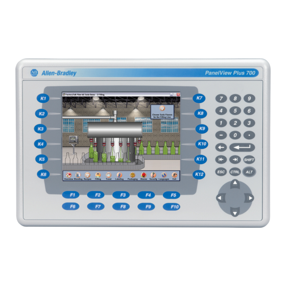
Table 5 - Display Features Item Feature Description Replaceable ID Label Allen-Bradley label that can be replaced with custom label. Display Analog resistive touch screen applies to touch-screen or combination keypad/touch-screen terminals. Numeric keypad 0…9, –, Backspace, Enter, Left and Right tab, Shift, Esc,... -
Page 17: Catalog Number Explanation
Overview Chapter 1 Catalog Number This is the catalog number explanation for configured units of the PanelView Plus 6 terminals. Explanation Input Display Display Communication Power Special Option Type Operating System Type Size 2711P- K = Keypad 7 = 6.5 in. C = Color 4 = Ethernet, RS-232 &... - Page 18 Chapter 1 Overview Table 7 - PanelView Plus 6 Terminals with Extended Features Cat. Nos. Display Communication Input Nonvolatile Flash/ Power RAM Memory Keypad Touch Keypad/Touch Size Type RS-232 Ethernet 700 Model 2711P-K7C4D9 2711P-T7C4D9 2711P-B7C4D9 6.5-in. Color • • 512 MB/512 MB 2711P-K7C4A9 2711P-T7C4A9 2711P-B7C4A9...
-
Page 19: Module Selections
Overview Chapter 1 Module Selections Display modules, logic modules, and communication modules can be ordered as separate components for field installation. Table 8 - Display Modules Marine Conformal Built-in Cat. No. Input Type Display Certified Coated Antiglare Overlay 700 Model 2711P-RDK7C Keypad 7-in. -
Page 20: Accessories
Chapter 1 Overview Table 9 - Logic Modules Power Nonvolatile Flash/ Conformal Cat. No. Communication Included Software Input RAM Memory Coated Without Extended Features 2711P-RP8A 512 MB/512 MB • Ethernet • Windows CE 6.0 operating system • RS-232 • FactoryTalk View Machine Edition runtime, 2711P-RP8D 512 MB/512 MB •... - Page 21 Overview Chapter 1 Table 13 - Backlight Replacements Number of Cat. No. Terminal Model Series Backlights 2711P-RL7C A and B 2711P-RL7C2 C and D 2711P-RL10C 1000 2711P-RL10C2 B and C 2711P-RL12C 1250 A and B 2711P-RL12C2 2711P-RL15C 1500 Table 14 - Antiglare Overlays Operator Input Cat.
- Page 22 Chapter 1 Overview Table 18 - Power Supply and Power Terminal Blocks Cat. No, Description Quantity 2711P-RY2032 Replacement battery 2711P-RTBAC3 AC power terminal block 2711P-RTBDC2 2-pin DC power terminal block Table 19 - Bezel Replacements Operator Input Cat. No. Terminal Model Keypad Touch Key/Touch 2711P-RBK7...
-
Page 23: Chapter Objectives
Chapter Install Terminal Chapter Objectives This chapter provides details on how to install your terminal in a panel. Topic Page Environment and Enclosure Information North American Hazardous Location Approval Outdoor Installation for High-bright Displays Required Tools Clearances Panel Cutout Dimensions Product Dimensions Mount the Terminal in a Panel Environment and Enclosure... -
Page 24: North American Hazardous Location Approval
Chapter 2 Install Terminal North American Hazardous Location Approval The following information applies when operating this Informations sur l’utilisation de cet équipement en equipment in hazardous locations. environnements dangereux. When marked, these products are suitable for use in "Class I, Les produits marqués "CL I, DIV 2, GP A, B, C, D"... -
Page 25: Usb Ports
Install Terminal Chapter 2 USB Ports The terminals contain USB host ports that comply with hazardous location environments. Field wiring compliance requirements are provided in compliance with the National Electrical Code, Article 500. Figure 3 - PanelView Plus 6 Terminals Control Drawing Associated Nonincendive Field Wiring Apparatus PanelView Plus 6 Host Product Nonincendive Field... -
Page 26: Outdoor Installation For High-Bright Displays
Chapter 2 Install Terminal The circuit parameters of the PanelView Plus 6 USB ports are given in Table 21 on page 25. The USB peripheral device and its associated cabling shall have circuit parameters with the limits given in Table 22 on page 25 for them to remain nonincendive when used with the PanelView Plus 6 USB port. -
Page 27: Using An Antiglare Overlay
Install Terminal Chapter 2 Using an Antiglare Overlay Ultraviolet (UV) radiation from the sun causes all plastics to fade or yellow, and become brittle over time. Using an antiglare overlay, catalog number 2711P-RGT12, will protect the front of the terminal from direct exposure to UV radiation and increase its field life. -
Page 28: Required Tools
Chapter 2 Install Terminal Required Tools These tools are required for panel installation: • Panel cutout tools • Small, slotted screwdriver • Torque wrench for tightening the terminal mounting clips Clearances Allow adequate spacing around the terminal, inside the enclosure, for adequate ventilation. -
Page 29: Product Dimensions
Install Terminal Chapter 2 Product Dimensions The table provides product dimensions for the terminals. The 1000 keypad and keypad/touch terminals are shown for illustrative purposes. All other terminal sizes look similar. Figure 4 - PanelView Plus 6 Terminal Dimensions - Model 1000 Table 24 - PanelView Plus 6 Terminal Dimensions Depth a Depth b... -
Page 30: Mount The Terminal In A Panel
Chapter 2 Install Terminal Mount the Terminal in a Mounting clips secure the terminal to the panel. The number of clips you use varies by terminal size. Panel ATTENTION: Disconnect all electrical power from the panel before making the panel cutout. Make sure the area around the panel cutout is clear. - Page 31 8 Clips ATTENTION: Tighten the mounting clips to the specified torque to provide a proper seal and to prevent damage to the product. Allen-Bradley assumes no responsibility for water or chemical damage to the product or other equipment within the enclosure because of improper installation.
- Page 32 Chapter 2 Install Terminal Notes: Rockwell Automation Publication 2711P-UM006A-EN-P - November 2010...
-
Page 33: Chapter Objectives
Chapter Connect Power Chapter Objectives This chapter covers wiring and safety guidelines, and procedures for connecting power. Topic Page Wiring and Safety Guidelines Remove and Install the Power Terminal Block DC Power Connections AC Power Connections Initial Startup Reset the Terminal Wiring and Safety Use publication NFPA 70E, Electrical Safety Requirements for Employee Workplaces, IEC 60364 Electrical Installations in Buildings, or other applicable... -
Page 34: Remove And Install The Power Terminal Block
Chapter 3 Connect Power Remove and Install the The terminals are shipped with a power terminal block installed. You can remove the terminal block for ease of installation, wiring, and maintenance: Power Terminal Block • Logic modules with a DC power input use a two-position terminal block. •... -
Page 35: Dc Power Connections
Connect Power Chapter 3 DC Power Connections DC-powered PanelView Plus 6 devices have an integrated, isolated 24V DC power supply with these power ratings: • 24V DC nominal (18…32V DC) • 70 W maximum (2.9 A at 24V DC) The power supply is internally protected against reverse polarity of the DC+ and DC- connections. -
Page 36: Connect Dc Power
Chapter 3 Connect Power The earth/ground terminal requires a minimum wire gauge. Table 26 - Earth/Ground Wire Specifications for DC Power Symbol Wire Type Wire Gauge Terminal Screw Torque Stranded or solid Cu 90 °C (194 °F) 2.1…5.3 mm 1.13…1.36 N•m (14…10 AWG) (10…12 lb•in) ATTENTION: Damage or malfunction can occur when a voltage potential... -
Page 37: Ac Power Connections
Connect Power Chapter 3 AC Power Connections PanelView Plus 6 devices with an integrated AC power supply have these power ratings: • 85…264V AC (47…63 Hz) • 160 VA max The input power terminal block supports these wire sizes. Table 27 - Wire Specifications for AC Input Power Terminal Block Dual-wire Single-wire Terminal Screw... -
Page 38: Connect Ac Power
Chapter 3 Connect Power Connect AC Power WARNING: Explosion Hazard Do not disconnect equipment unless power has been switched off and area is known to be nonhazardous. Disconnect all power before installing or replacing components. Failure to disconnect power may result in electrical shock or damage to the terminal. ATTENTION: Improper wiring of the power terminals may result in voltage at the communication connector shells. -
Page 39: Initial Startup
Connect Power Chapter 3 Initial Startup The first time you start the system, the terminal goes through its power-up sequence and launches FactoryTalk View ME Station, the Configuration mode of the terminal. You can change the action the terminal takes on startup by choosing Terminal Settings>Startup Options. -
Page 40: Reset The Terminal
Chapter 3 Connect Power Reset the Terminal Use the reset switch on the back of the terminal to restart the terminal without having to disconnect and reapply power. After a reset, the terminal performs a series of startup tests and then takes one of these actions: •... -
Page 41: Configuration Mode
Chapter Configuration Mode Chapter Objectives This chapter shows how to use FactoryTalk View ME Station on your terminal to load and run applications, configure startup options, access the Windows Explorer desktop, configure communication, and perform other terminal operations. Topic Page Topic Page Access Configuration Mode... - Page 42 Chapter 4 Configuration Mode Figure 6 - FactoryTalk View ME Station Configuration Mode Dialog Box Name of application that is currently loaded. Appears only if application is loaded. Displays network information every 60 seconds. If the network is shutdown the IP address and subnet mask appear as 0.0.0.0.
-
Page 43: Input Panel
Configuration Mode Chapter 4 Input Panel When you press a button or function key on a data entry field, the input panel opens. This is where you enter or edit data: • If a field is restricted to a numeric value, only the 0…9 keys will be enabled. •... -
Page 44: Terminal Settings
Chapter 4 Configuration Mode Terminal Settings You can modify settings on the terminal that are not specific to the application. 1. Select Terminal Settings from the FactoryTalk View ME Station Configuration mode dialog. Moves selection bar up or down. Accesses settings for selected function. - Page 45 Configuration Mode Chapter 4 Figure 8 - Terminal Settings Menu Structure Alarms page 75 Diagnostics Setup page 71 Display Display Intensity Display Temperature Cursor Screen Saver page 63 page 63 page 64 page 64 Desktop Access page 50 File Management Copy Files Delete Files Copy Applications...
-
Page 46: Load And Run Application
Chapter 4 Configuration Mode Load and Run Application Before running a FactoryTalk View Machine Edition .mer application, you must first load the application. You can load an .mer application from internal flash memory in the terminal, an SD card, or a USB flash drive. List of FactoryTalk View .mer applications stored in terminal Moves... -
Page 47: Startup Options
Configuration Mode Chapter 4 Startup Options You can specify what action the terminal takes on startup or a reset. This Start-up Option Performs This Action Typical System Do not start FactoryTalk Launches the Windows Explorer desktop on Open View ME Station startup. -
Page 48: Enter Configuration Mode On Startup
Chapter 4 Configuration Mode Enter Configuration Mode on Startup Follow these steps to automatically launch the FactoryTalk View ME Station Configuration mode dialog on startup. 1. Choose Terminal Settings>Startup Options. 2. Press the On Startup button to select Go to Configuration Mode. 3. -
Page 49: Run The Loaded Application On Startup
Configuration Mode Chapter 4 Run the Loaded Application on Startup Follow these steps to run the FactoryTalk View .mer application currently loaded in the terminal on startup. This is typical when running a closed system. 1. Select Terminal Settings>Startup Options. 2. -
Page 50: Desktop Access
Chapter 4 Configuration Mode Desktop Access You can allow or restrict access to the Windows desktop on all PanelView Plus 6 terminals. From the desktop, you can perform system and control panel operations, or run third-party applications. Terminals with extended features can additionally run viewers, media players, and launch the web browser. -
Page 51: Disable Desktop Access
Configuration Mode Chapter 4 5. Press OK to exit Desktop Access Management, then Close to exit Terminal Settings. 6. Press Exit from FactoryTalk View ME Station to access the desktop. With desktop access set to allow, you will not be required to enter a password. -
Page 52: Set A Desktop Password
Chapter 4 Configuration Mode Set a Desktop Password If you disallow or restrict access to the desktop, you will be required to IMPORTANT set a password along with a challenge question. Follow these steps to set a new password. 1. Press the Set Password button from Desktop Access Management. 2. -
Page 53: Reset The Desktop Password
Configuration Mode Chapter 4 Reset the Desktop Password To clear the current password and reset a new password, you must first correctly respond to the current challenge question. If you cannot remember the response, you will have to restore the terminal to its factory default settings. Refer to Access Maintenance Operations on page 151 for details. -
Page 54: Communication Setup
Chapter 4 Configuration Mode Communication Setup You configure communication for your application and controller by using RSLinx Enterprise software: • Access KEPServer Serial Port ID’s. • Edit the driver settings for the protocol used by your .mer application. • Edit the device address of the controller on the network. Configure KEPServer Serial Port ID’s To access KEPServer serial communication, you must have KEPServer Enterprise installed on your terminal. - Page 55 Configuration Mode Chapter 4 Table 33 - Communication Driver Properties Field Description Valid Values Serial Properties Use Auto Config Automatically or manually configures the baud rate, parity, and error Yes (auto configure) checking parameters. No (manual configure) Device The serial device terminal is connected to. PLC-5, SLC, MicroLogix, Logix Platform Error Check...
-
Page 56: Configure A Device Address
Chapter 4 Configuration Mode Configure a Device Address Follow these steps to edit the address of a device such as a logic controller. 1. From the RSLinx Configuration dialog, select a device node. 2. Press the Edit Device button to view the device name and current address. 3. - Page 57 Configuration Mode Chapter 4 Follow these steps to view or enter the IP address of your terminal. 1. Select Terminal Settings>Networks and Communications>Network Connections>Network Adapters. 2. Press the IP Address button to view or modify the IP address. 3. Press the DHCP button to enable or disable DHCP assignment of addresses.
-
Page 58: Set The Ethernet Link Speed
Chapter 4 Configuration Mode Set the Ethernet Link Speed You can set the speed and duplex setting of the Ethernet link. 1. Select Terminal Settings>Networks and Communications>Network Connections>Network Adapters. 2. Press the Settings button to view or modify the Ethernet link settings. 3. -
Page 59: View Or Change Terminal Device Name
Configuration Mode Chapter 4 Follow these steps to define a name server address. 1. Select Terminal Settings>Networks and Communications>Network Connections>Network Adapters. 2. Press a button to enter a name server address. Field Description Valid Values Primary DNS The address of the primary DNS resolver. xxx.xxx.xxx.xxx Secondary DNS The address of the secondary DNS resolver. -
Page 60: Authorize Terminal To Access Network Resources
Chapter 4 Configuration Mode Authorize Terminal to Access Network Resources The terminal can access network resources with proper identification. A user name, password, and domain must be provided by your network administrator. 1. Select Terminal Settings>Network and Communications>Network Connections>Network Identification. 2. -
Page 61: Delete Log Files
Configuration Mode Chapter 4 2. Press the Source button to choose the storage location of the application or font file you want to delete. • Internal Storage - internal flash memory of the terminal • External Storage 1 - SD card loaded in the card slot of the terminal •... -
Page 62: Copy Application File Or Font File
Chapter 4 Configuration Mode Copy Application File or Font File You can copy Factory Talk View application .mer files or font files from one storage location to another in the terminal. The procedure for copying an application file or a font file between storage locations is the same. 1. -
Page 63: Display Settings
Configuration Mode Chapter 4 Display Settings For the terminal display, you can adjust its intensity, view its temperature, configure the screen saver, or enable/disable the screen cursor. Adjust the Display Intensity You can modify the intensity of the terminal backlight. You can use the default intensity of 100% or you can change the intensity for runtime operations. -
Page 64: Configure The Screen Saver
Chapter 4 Configuration Mode Configure the Screen Saver The screen saver on the terminal activates after an idle period using a specific intensity. The default idle timeout is 10 minutes. You can adjust the idle timeout and intensity level for the screen saver, disable the screen saver, and enable or disable the screen saver bitmap. -
Page 65: Input Device Settings
Configuration Mode Chapter 4 Input Device Settings You can adjust the settings for input devices used by the terminal including the keypad, attached keyboard, mouse, touch screen, and string entry popup. Configure Keyboard or Keypad Settings You can adjust settings for keys on an attached keyboard or the terminal keypad. 1. -
Page 66: Change The Popup For String Entry
Chapter 4 Configuration Mode Change the Popup for String Entry You can specify whether to use the standard input panel for data entry or a string popup. The popup keyboard is the default. 1. Select Terminal Settings>Input Devices>Keypad>String Popup. 2. Press the Invoke pop-up character input instead of popup keyboard button to select the preferred input method for string entry. -
Page 67: Set Double-Tap Sensitivity For A Touch Screen
Configuration Mode Chapter 4 Set Double-tap Sensitivity for a Touch Screen You can set and test the sensitivity for both the speed and physical distance between touch-screen presses. The process is identical to setting the double-tap sensitivity for the mouse. 1. -
Page 68: Configure Print Options
Chapter 4 Configuration Mode Configure Print Options You can configure settings for printing displays, alarm messages, or diagnostic messages from FactoryTalk View ME .mer applications. The general setup for printing displays and messages is the same, however, the advanced settings are different. - Page 69 Configuration Mode Chapter 4 • Advanced settings for printing diagnostic and alarm messages determines when to print messages sent to the network or USB port. Print Messages After Default Value Example Specified number of messages 60 messages When the queue has 60 messages, the messages are printed regardless of how long they have been in the queue.
-
Page 70: Check Integrity Of Application Files
Chapter 4 Configuration Mode Check Integrity of It is recommended that you periodically check the integrity of the FactoryTalk View .mer application file that is currently loaded in the terminal and the runtime Application Files files. All errors, warnings, and information messages generated by these files are logged to a file. -
Page 71: Configure Diagnostics
Configuration Mode Chapter 4 Configure Diagnostics You can configure diagnostics for the current computer. To access diagnostics, select Terminal Settings>Diagnostic Setup from the Configuration Mode main dialog. You will see a tree view of diagnostic nodes. To access the Remote Log Setup or Message Routing, select the node and then the Edit button. -
Page 72: View And Clear The System Event Log
Chapter 4 Configuration Mode View and Clear the System The System Event Log dialog displays a list of warnings, errors, and events logged by the terminal. The log provides a time stamp of when each event occurred and Event Log text describing the event. -
Page 73: System Information
Configuration Mode Chapter 4 System Information From Configuration mode, you can view terminal information and firmware revision information for software installed on a terminal. This information may be useful during troubleshooting. View Terminal Information The read-only information is provided for the terminal: •... - Page 74 Chapter 4 Configuration Mode 2. Press the Memory Allocation button to view the following. • Amount of allocated storage or program memory • Amount of storage or program memory in use • Amount of available flash memory 3. Press Close to return to previous dialog. 4.
-
Page 75: Display Factorytalk View Me Station Information
Configuration Mode Chapter 4 Display FactoryTalk View ME Station Information You can display the firmware and version information for installed system components on your terminal and technical support information. 1. Select Terminal Settings>System Information>About FactoryTalk View ME Station. 2. Press the Technical Support button to display the support phone number and website for your terminal . -
Page 76: Time And Date Settings
Chapter 4 Configuration Mode Time and Date Settings You can change the date, time, time zone, and regional settings for terminal operations. Change the Date for Terminal Operations Follow these steps to adjust the date for terminal operations. 1. Select Terminal Settings>Time/Date/Regional Settings>Date. The current date appears in the Year, Month, and Day fields. -
Page 77: Change The Time Zone For Terminal Operations
Configuration Mode Chapter 4 Change the Time Zone for Terminal Operations You can view or modify the current time zone that is installed on the terminal. Time zones are installed as a part of the operating system. Changing the time zone adjusts the current time and date to match the new time zone. -
Page 78: Regional Settings
Chapter 4 Configuration Mode Regional Settings You can adjust regional settings for a specific language installed on the terminal, including the date, time and numeric formats. Regional settings are accessed by choosing Terminal Settings>Time/Date/Regional Settings>Regional Settings. The current language is shown at the bottom of the Regional Settings dialog. Select a Language Before you can modify regional settings for a language, you need to select a language installed on the terminal. -
Page 79: Change The Time Format For A Language
Configuration Mode Chapter 4 Change the Time Format for a Language Follow these steps to change the time format for the selected language. 1. Select Terminal Settings>Time/Date/Regional Settings>Regional Settings>Time Format. The current time is shown using the currently selected format. 2. -
Page 80: Change The Short Date Format For A Language
Chapter 4 Configuration Mode Change the Short Date Format for a Language Follow these steps to change the short date format for the selected language. 1. Select Terminal Settings>Time/Date/Regional Settings>Regional Settings>Short Date Format. The current date is shown in the selected, short date format. Field Short Date Formats Example... -
Page 81: Change The Long Date Format For A Language
Configuration Mode Chapter 4 Change the Long Date Format for a Language Follow these steps to change the long date format used by the selected language. 1. Select Terminal Settings>Time/Date/Regional Settings>Regional Settings>Long Date Format. The current date is shown in the selected long date format. 2. -
Page 82: Font Linking
Chapter 4 Configuration Mode Font Linking Font linking lets you run a translated application on the terminal by linking a font file to the base font (for example, linking a Chinese font file to the base font Arial). For more details on preinstalled terminal fonts and additional fonts available for downloading, see Fonts Resident on Terminal on page 159. -
Page 83: Windows Ce Operating System
Chapter Windows CE Operating System Chapter Objectives All PanelView Plus 6 terminals run the Windows CE 6.0 operating system (OS) providing the foundational OS elements for the majority of user needs. PanelView Plus 6 terminals with extended features provide an additional level of support for users with more complex application requirements. -
Page 84: Application Support
Chapter 5 Windows CE Operating System • PDF reader • VNC server and client viewer The platform distributes a VNC client, vncviewer.exe, that can be deployed to a personal computer. You can use this VNC client to connect, view, and control the VNC server on the Windows CE platform. The Windows Explorer shell supports right-click functionality. -
Page 85: Server Support
Windows CE Operating System Chapter 5 Server Support This table lists servers supported by the Windows CE 6.0 operating system. Table 34 - Windows CE 6.0 Server Support Server Default Description Support State Web server Enabled The web server delivers content, such as Web pages, using the HTTP protocol over the Web. -
Page 86: Windows Control Panel
Chapter 5 Windows CE Operating System Windows Control Panel The Windows control panel is the primary desktop interface for configuring a PanelView Plus 6 terminal. You can set system-wide properties, such as network configuration, screen saver configuration, and touch screen calibration. Table 36 lists the control panel applets. -
Page 87: Hardware Monitor
Windows CE Operating System Chapter 5 Hardware Monitor The PanelView Hardware Monitor applet provides status and troubleshooting information for the terminals including processes, system event log details, and monitoring of battery voltages, temperatures, and system usage, for example, CPU and memory loading. Processes The Processes tab of the Hardware Monitor applet shows all processes currently running on the PanelView Plus 6 terminal and memory usage of each process. -
Page 88: Monitors
Chapter 5 Windows CE Operating System Monitors The Monitors tab of the PanelView Hardware Monitor applet provides continuous temperature, voltage, and load information for the terminal. Battery Voltage The Monitors tab provides a visual status and voltage reading of the battery for the real-time clock. -
Page 89: Keypad Properties
Windows CE Operating System Chapter 5 Keypad Properties The Keypad Properties applet lets you adjust settings for the membrane keypad of your terminal. Repeat Tab The Repeat tab on the Keypad Properties applet enables and disables the character repeat behavior of keys on the keypad. Use the Keyboard applet to manage properties of a USB keyboard. -
Page 90: Display Properties
Chapter 5 Windows CE Operating System Display Properties The Display Properties applet provides tabs to control the desktop background image and appearance, the brightness of the backlight, and screen saver settings. Desktop Background The Background tab of the Display Properties applet controls the background bitmap used by the desktop. -
Page 91: Screen Saver
Windows CE Operating System Chapter 5 Screen Saver The screen saver extends the lifetime of the display by dimming the backlight when the terminal is idle. The screen saver will activate and display a moving bitmap at a reduced brightness level after a continuous idle time. When the screen saver is deactivated, the display brightness returns to its normal brightness level. -
Page 92: Network Servers
Chapter 5 Windows CE Operating System Network Servers The Network Server applet shows servers that are supported by the terminal and lets you enable (start) or disable (stop) each server. The buttons are color coded: • Green indicates the server is currently running and will be automatically started at system startup. -
Page 93: Startup Options
Windows CE Operating System Chapter 5 Startup Options The Startup Options tab of the System Information dialog lets you show or hide battery warnings at startup, show or hide watchdog errors at startup, and launch the platform as either an open or closed system. Battery Warnings If the battery is low, missing, or dead, a warning will display each time the terminal starts up. -
Page 94: Device Name
Chapter 5 Windows CE Operating System Open or Closed Shell At startup, you can run the terminal platform as either open or closed. Shell Option Description Open system Launches the Windows CE desktop at startup. Closed system (default) Launches FactoryTalk View ME Station at startup. You can also allow or restrict access to the Windows CE desktop within FactoryTalk View ME Station by choosing Terminal Settings>Desktop Access Setup. -
Page 95: Printer Support
Windows CE Operating System Chapter 5 Printer Support The PanelView Plus 6 platform supports selected USB printers such as Canon, Epson, Hewlett-Packard, and Brother. Automatic printer installation using plug- and-play capabilities is supported as well as manual installation if a suitable printer driver is available. - Page 96 Chapter 5 Windows CE Operating System 3. Verify printer installation from the desktop control panel by opening the Printers applet. You should see an icon for the Deskjet 5650C printer. The check mark indicates this is as the default printer. 4.
-
Page 97: Manual Printer Installation
Windows CE Operating System Chapter 5 Manual Printer Installation Follow these steps to manually set up a supported printer. 1. Connect the printer to the USB port. 2. Plug the power cord of the printer into an outlet and turn the printer on. 3. -
Page 98: Pdf Reader
Chapter 5 Windows CE Operating System PDF Reader A PDF reader is available on all PanelView Plus 6 terminals and provides typical PDF view and search functions. You can run this reader from the Windows desktop or from a command prompt. When viewing a PDF document, you can initiate functions from the menu or toolbar. -
Page 99: Command Prompt Parameters
Windows CE Operating System Chapter 5 Command Prompt Parameters You can run the PDF reader from the Windows Command Prompt by entering Start>Programs>Command Prompt and executing the command parameters in Table Command Prompt Syntax Foxitreader “file_path/file-name.pdf” parameter parameter_ value • Enter the file path and file name in double quotes and use a forward slash in the file path, and to separate the file path from the file name. - Page 100 Chapter 5 Windows CE Operating System Notes: Rockwell Automation Publication 2711P-UM006A-EN-P - November 2010...
-
Page 101: Chapter Objectives
Chapter Install and Replace Components Chapter Objectives This chapter shows provides topics on how to install or replace components of the PanelView Plus 6 terminals. Topic Page Install or Replace the Logic Module Install or Replace a Communication Module Replace the Display Module Replace the Bezel Replace the Battery Replace the Backlight... -
Page 102: Install Or Replace The Logic Module
Chapter 6 Install and Replace Components Install or Replace the Logic If the display module and logic module are ordered as separate components, attach the logic module to the display module before panel installation. Module 1. Make sure power is disconnected power from the terminal. 2. -
Page 103: Install Or Replace A Communication Module
Install and Replace Components Chapter 6 4. Remove the four screws that secure the communication module, if attached, to the logic module and set the communication module aside. Communication Module Screw Logic Module Captive Screw Display Module 5. Loosen the four captive screws that secure the logic module to the display module. - Page 104 Chapter 6 Install and Replace Components 2. If the display module is removed from the panel, set the terminal, display-side down, on a clean, flat, stable surface. Connector for Communication Module 3. Position the communication module over the logic module so that the connector on the bottom of the module aligns with the connector on the logic module.
-
Page 105: Replace The Display Module
Install and Replace Components Chapter 6 Follow these steps to replace a communication module. 1. Disconnect power from the terminal. 2. Disconnect communication cables from the module. WARNING: Do not connect or disconnect any communication cable with power applied to this device or any device on a network. -
Page 106: Replace The Bezel
Chapter 6 Install and Replace Components 7. Position the logic module over the new display module so that the connectors align. 8. Push down on the logic module until firmly seated. 9. Tighten the four captive secures that secure the logic module to the display module and torque to 0.58 N•m (5…7 lb•in). - Page 107 Install and Replace Components Chapter 6 4. Disconnect the touch screen connector. Plate Touch Screen Connector 5. Remove the screws from the back of the display module. The number of screws varies for each terminal type. Display Module Bezel 6. Remove the sealing gasket. 7.
-
Page 108: Replace The Display Module Bezel
Chapter 6 Install and Replace Components Replace the Display Module Bezel Follow these steps to replace the display module bezel. 1. Make sure the bezel is free of lint and marks before attaching. 2. Attach the connectors. • Function key connector •... -
Page 109: Replace The Battery
Install and Replace Components Chapter 6 Replace the Battery The terminals have a lithium battery that is used by the real-time clock. It is not used for backup or retention. ATTENTION: To avoid voiding your product warranty, use only the Rockwell Automation approved battery. - Page 110 Chapter 6 Install and Replace Components 6. Locate the battery on the circuit board. 7. Remove the battery by lifting up the side of the battery. 8. Insert the new battery. • Use only replacement battery, catalog number 2711P-RY2032 ,or an IMPORTANT equivalent CR2032 lithium coin cell battery.
-
Page 111: Replace The Backlight
Install and Replace Components Chapter 6 Replace the Backlight All of the display modules have replaceable backlights except for the 1250 high-bright displays. Table 42 - Backlight Replacements Use Cat. No. For Display Series # of Backlights 2711P-RL7C A and B 2711P-RL7C2 C and D 2711P-RL10C... - Page 112 Chapter 6 Install and Replace Components 4. Lift the LCD display and detach the display connector from the circuit board. The circuit board layout may vary for each terminal model. The location of the connector varies by model. Display Connector 5.
- Page 113 Install and Replace Components Chapter 6 b. Insert the new backlight. Backlight 7. Follow these steps for the 1250 and 1500 displays. a. Remove the screws that secure the backlights and remove the backlights. For the 1250 series A and B displays, the two backlights are each secured with two screws.
-
Page 114: Remove The Product Id Label
You can remove the label on your terminal and attach your own label. Label 1. Remove the Allen-Bradley label using your fingers or a tweezers. 2. Clean area with damp cloth and isopropyl alcohol. 3. Remove adhesive backing of OEM label and affix over area where label was located. -
Page 115: Load An Sd Card Or Usb Flash Drive
Install and Replace Components Chapter 6 3. Pull the legend inserts out from the slots on the bezel. 4. Slide the new legend strips into the same slots until only the end tab is visible. 5. Replace the display module bezel. Load an SD Card or USB All logic modules have an SD (secure digital) card slot and two USB host ports for external storage:... -
Page 116: Clean The Display
Chapter 6 Install and Replace Components Clean the Display Use a protection antiglare overlay for easier cleaning of the display screen. ATTENTION: Use of abrasive cleaners or solvents may damage the display. Do not scrub or use brushes. Follow these steps to clean the display screen. 1. -
Page 117: Chapter Objectives
Chapter Terminal Connections Chapter Objectives This chapter provides topics on network and device connections. Topic Page Wiring and Safety Guidelines Connections to Controllers Communication Port Isolation USB Ports Serial Connections Ethernet Connections DH-485/DH+ Communication Module ControlNet Module Wiring and Safety Use publication NFPA 70E, Electrical Safety Requirements for Employee Workplaces, IEC 60364 Electrical Installations in Buildings or other applicable Guidelines... -
Page 118: Connections To Controllers
Chapter 7 Terminal Connections Connections to Controllers The tables provide a summary of PanelView Plus 6 connections to controllers and interface modules for runtime communication. Table 43 - Runtime Communication Cables: PanelView Plus 6 Terminals to SLC Controllers SLC 500, 5/01, 5/02 SLC 5/03, 5/04, 5/05 SLC 5/03 SLC 5/04... -
Page 119: Communication Port Isolation
Terminal Connections Chapter 7 Table 45 - Runtime Communication Cables: PanelView Plus 6 Terminals to Logix Controllers ControlLogix CompactLogix Protocol PanelView Plus 6 Comm Port CH0 (9-pin RS-232) CH0 (9-pin RS-232) (DF1) (DF1 or DH-485) 2711-NC13 (5 m/16 ft) 2711-NC13 (5 m/16 ft) RS-232 (DF1) port (9-pin) 2711-NC14 (10 m/32 ft) 2711-NC14 (10 m/32 ft) -
Page 120: Usb Ports
Chapter 7 Terminal Connections USB Ports The terminals have two USB 2.0 host ports and one mini USB 2.0 device port. Figure 10 - USB Ports Mini USB Device Port Two USB Host Ports The mini USB (type B) device port supports a connection to a host computer using TCP/IP communication and the USB function RNDIS client driver. -
Page 121: Serial Connections
Terminal Connections Chapter 7 Serial Connections The logic module of the terminals has a serial RS-232 port that supports these connections: • DH-485 communication through a serial connection • DF1 full-duplex communication with controllers using direct connections or modem connections •... -
Page 122: Modem Connection
Chapter 7 Terminal Connections Modem Connection Wire or radio modem communication is possible between the terminal and controller. Each modem must support full duplex communication. Refer to your modem user manual for details on settings and configuration. Figure 12 - Modem Connection PanelView Plus 6 Terminal Optical Isolator Controller... -
Page 123: Computer Connections
Terminal Connections Chapter 7 Computer Connections The RS-232 serial port of the logic module supports application uploads and downloads between the terminal and a computer using a direct connection. Figure 13 - Serial Port Connection to Computer Computer PanelView Plus 6 Terminal RS-232 Port Cables Cat. -
Page 124: Ethernet Connections
Chapter 7 Terminal Connections Ethernet Connections The Ethernet port on the logic module that supports these connections: • EtherNet/IP communication • Third-party Ethernet communication • Auto MDI/MDIX connections • Network connections • Application uploads/downloads • Printing Ethernet Connector The base-configured unit of the terminals has an RJ45, 10/100 Base-T connector for EtherNet/IP or Ethernet TCP/IP network communication. -
Page 125: Ethernet Cable
Terminal Connections Chapter 7 Ethernet Cable Use Belden 7921A shielded CAT5E cable according to TIA 568-B.1 and RJ45 connector according to IEC 60603-7 for compliance with Marine emission limits and the European Union 89/336/EEC EMC Directive. The maximum length of the Ethernet cable between the logic module’s Ethernet port and a 10/100 Base-T port on an Ethernet hub (without repeaters or fiber) is 100 m (328 ft). -
Page 126: Dh-485/Dh+ Communication Module
Chapter 7 Terminal Connections DH-485/DH+ Terminals with a catalog number 2711P-RN6 or 2711P-RN6K communication module support communication with these networks: Communication Module • DH+ networks • DH-485 networks The communication module has a separate port for each communication protocol. You can communicate with only one network at one time. Figure 15 - DH-485/DH+ Communication Module Connectors Allen Bradley... -
Page 127: Dh-485 Network Port Wiring
Refer to the figures to attach the RS-485 connector to a Belden 3106A or 9842 cable. Refer to Connections to Controllers on page 118 if you are using standard Allen-Bradley cables. A daisy-chained network is recommended. We do not recommend a IMPORTANT hybrid star/daisy chain networks as shown. -
Page 128: Dh+ Network Connections
Chapter 7 Terminal Connections DH+ Network Connections Use a Belden 9463 twin-axial or equivalent cable, catalog number 1770-CD, to connect a terminal to a DH+ link. You can connect a DH+ link in two ways: • Trunk line/drop line - from the drop line to the connector screw terminals on the DH+ connectors of the processor. -
Page 129: Controlnet Module
Terminal Connections Chapter 7 ControlNet Module Terminals with a catalog number 2711P-RN15S or 2711P-RN15SK communication module support ControlNet communication and the transfer of applications between devices on a ControlNet network. Additional Resources For more information on ControlNet products, refer to these publications: •... -
Page 130: Software And Firmware Requirements
Software and Firmware Requirements The software and firmware must be installed on the development computer and the PanelView Plus 6 terminal to configure and communicate with an Allen-Bradley controller on a ControlNet network. Table 57 - ControlNet Unscheduled Communication Software/Firmware... -
Page 131: Controlnet Module Connectors
Terminal Connections Chapter 7 ControlNet Module Connectors Figure 20 - Cat. No. 2711P-RN15S or 2711P-RN15SK Communication Module Status Indicator A Pin NAP Signal Status Indicator B Signal Common Pin 1 No Connection TX_H Network Access Port (NAP) TX_L RJ-45 connector for temporarily RX_L connecting programming terminals to devices on a ControlNet network... -
Page 132: Module Connection To Controlnet Network
Chapter 7 Terminal Connections Do not connect to a network using both the redundant cable BNC IMPORTANT connector and the Network Access Port (NAP). Module Connection to ControlNet Network You can make these connections with the ControlNet communication module: • Connect directly to a ControlNet network, which requires a tap. •... -
Page 133: Firmware Upgrades
Chapter Firmware Upgrades Chapter Objectives This chapter provides topics on how to upgrade firmware in a terminal. Topic Page Terminal Firmware Download Firmware Files Firmware Upgrade Wizard Upgrading Terminal Firmware from a Storage Device Upgrade Terminal Firmware over the Network Terminal Firmware Firmware components are packaged as execute-in-place (XIP) regions in a single System Code (SC) .img file. -
Page 134: Download Firmware Files
Chapter 8 Firmware Upgrades Download Firmware Files Before upgrading your terminal firmware, you need to download the appropriate firmware installation package, for example, PVP700-1500_60000.exe, from the Rockwell Automation customer website. This installation package contains: • Firmware Upgrade Package (FUP) contains an autorun executable and the new firmware files. -
Page 135: Upgrading Terminal Firmware From A Storage Device
Firmware Upgrades Chapter 8 Upgrading Terminal Upgrading firmware from a storage device is a two-step process. First, you create a firmware upgrade card with the required firmware files. Secondly, you load the Firmware from a Storage card in the target terminal to upgrade the firmware. Device The firmware upgrade card can be a USB flash drive or an SD card. - Page 136 Chapter 8 Firmware Upgrades 5. From this dialog, optionally select the KEPServer drivers you want installed on your terminal, then click Next. The final dialog summarizes your choices for creating the firmware upgrade card. 6. Click Finish to copy the firmware files to the firmware upgrade card.
-
Page 137: Upgrade Terminal Firmware Using Firmware Upgrade Card
Firmware Upgrades Chapter 8 Upgrade Terminal Firmware Using Firmware Upgrade Card Follows these steps to transfer firmware files from the USB flash drive or SD card to the terminal. This is the firmware upgrade card you just created. • IMPORTANT Do not remove or accidently disconnect the USB flash drive or SD card while a firmware upgrade is in process. -
Page 138: Upgrade Terminal Firmware Over The Network
Chapter 8 Firmware Upgrades Upgrade Terminal You can upgrade firmware in a terminal connected to a computer over a direct network connection. The network connection requires a computer running the Firmware over the Network Firmware Upgrade Wizard (FUW) and RSLinx Enterprise software, version 5.0 or later. - Page 139 Firmware Upgrades Chapter 8 5. Navigate to and select the terminal to receive the firmware update, then click Next. 6. Follow these steps from this dialog box. a. Browse to the location of the firmware source files on your computer, where the FUP was installed.
- Page 140 Chapter 8 Firmware Upgrades The final dialog summarizes your choices for upgrading the terminal firmware. 8. Click Finish to update the firmware in the terminal. 9. Click Yes to continue with the update. A progress bar will automatically update as firmware files are copied to the terminal.
-
Page 141: Troubleshoot The System
Chapter Troubleshoot the System Chapter Objectives This chapter provides information on how to isolate and correct common operating anomalies. Topic Page Status Indicators Isolate the Anomaly Start-up Messages and Codes Check Terminal Components Application Does Not Run Configuration Mode Access File System Errors Advanced Diagnostics Access Maintenance Operations... -
Page 142: Isolate The Anomaly
Chapter 9 Troubleshoot the System Isolate the Anomaly This section provides general troubleshooting information to assist you when trying to isolate anomalies. Check for Adequate Power A terminal that does not receive adequate power could result in unpredictable behavior. Refer to Appendix A, Specifications, for power requirements. -
Page 143: Check The Start-Up Messages And Codes
Troubleshoot the System Chapter 9 Check the Start-up Messages and Codes Refer to Start-up Messages and Codes on page 144 for a list of message states and error codes that may appear on the splash screen during startup. Check Voltages and Temperatures Check the battery voltage, processor temperature, and display temperature: •... -
Page 144: Start-Up Messages And Codes
Chapter 9 Troubleshoot the System Start-up Messages and The splash screen reports actions and status conditions that occur during startup. This includes firmware and hardware revision information. Codes Figure 22 - Splash Screen Status or State Message Error Code 2010 Rockwell Automation, Inc. Progress Bar Logic Module All Rights Reserved... - Page 145 Troubleshoot the System Chapter 9 Table 61 - Start-up Messages and Codes State Message Description State Message Code Recommended Action Firmware Installation and Loading Load firmware image into RAM Update Messages during firmware installation and loading are for information. Write firmware image to storage Update Load factory-default firmware image into RAM Restore...
-
Page 146: Check Terminal Components
Chapter 9 Troubleshoot the System Check Terminal This section provides tips on how to isolate anomalies with the display, touch screen, keypad, attached keyboard, or mouse. If you are unable to resolve the Components anomaly, replace the display. Table 62 - Resolve Anomalies with Display Symptom Recommended Action The display is dim or unreadable. - Page 147 Troubleshoot the System Chapter 9 Table 64 - Resolve Anomalies with Mouse Symptom Recommended Action The mouse is not operating correctly. Check the USB cable and connection. Detach and then reattach the mouse. Cycle power to the terminal. The screen cursor may not be visible or the mouse Check if the screen cursor is disabled: settings may need adjusting.
-
Page 148: Ethernet Connection
Chapter 9 Troubleshoot the System Ethernet Connection This table provides tips on how to isolate Ethernet anomalies. Table 66 - Resolve Ethernet Anomalies Action Description Check the status indicators at the Ethernet connection • Green indicates a communication link and should be on. •... -
Page 149: Application Does Not Run
Troubleshoot the System Chapter 9 Application Does Not Run If a terminal application does not run, there may be an issue with the FactoryTalk View Machine Edition (ME) application. Verify that a startup screen was configured and that the runtime file is a compatible version. If the terminal application does not run at startup, try to run the application manually. -
Page 150: Advanced Diagnostics
Chapter 9 Troubleshoot the System Advanced Diagnostics Ping and ipconfig are valuable tools for network debugging along with some knowledge of IP and the Winsock error codes: • Try to ping the destination host. • Check the destination address. • Check whether you have a router configured in your network system (your WinSock implementation). -
Page 151: Access Maintenance Operations
Troubleshoot the System Chapter 9 Access Maintenance The terminal typically launches the Windows desktop or a FactoryTalk View ME application on startup. You can also start the system in Maintenance mode for Operations diagnostic and repair purposes. Follow these steps to access Maintenance actions at startup. All terminals require an attached USB keyboard to navigate in Maintenance mode. - Page 152 Chapter 9 Troubleshoot the System 2. Press the up and down arrow keys on the keypad or attached keyboard to move up and down the list or maintenance options: • Continue booting with selection option. • Special Boot Action • Display Resolution 3.
- Page 153 Troubleshoot the System Chapter 9 Table 67 - Maintenance Startup Operations Operation Description None Exits Maintenance mode and continues with a normal restart. Starts the system in Safe operating mode. This is a diagnostic mode with reduced functionality allowing for recovery from a software anomaly.
- Page 154 Chapter 9 Troubleshoot the System Notes: Rockwell Automation Publication 2711P-UM006A-EN-P - November 2010...
-
Page 155: Technical Specifications
Appendix Specifications Technical Specifications Table 68 - Technical Specifications - 2711P-Kxxxx8, 2711P-Txxxx8, 2711P-Bxxxx8, 2711P-Kxxxx9, 2711P-Txxxx9, 2711P-Bxxxx9 Attribute 2711P-Kxxxx8, 2711P-Txxxx8, 2711P-Bxxxx8, 2711P-Kxxxx9, 2711P-Txxxx9, 2711P-Bxxxx9 Operating system Microsoft Windows CE 6.0 R3 x86 - 1.0 GHz Display type Color active matrix, thin film transistor (TFT), liquid crystal display (LCD) Display size 6.5 in. - Page 156 Appendix A Specifications Table 68 - Technical Specifications - 2711P-Kxxxx8, 2711P-Txxxx8, 2711P-Bxxxx8, 2711P-Kxxxx9, 2711P-Txxxx9, 2711P-Bxxxx9 Attribute 2711P-Kxxxx8, 2711P-Txxxx8, 2711P-Bxxxx8, 2711P-Kxxxx9, 2711P-Txxxx9, 2711P-Bxxxx9 Electrical Input voltage, DC 24V DC nom (18…32V DC) Power consumption, DC 70 W max (2.9 A at 24V DC) 39 W typical (1.6A @ 24V DC) Input voltage, AC 85…264V AC...
-
Page 157: Environmental Specifications
Specifications Appendix A Environmental Table 69 - Environmental Specifications - 2711P-Kxxxx8, 2711P-Txxxx8, 2711P-Bxxxx8, 2711P-Kxxxx9, 2711P-Txxxx9, 2711P-Bxxxx9 Specifications Attribute 2711P-Kxxxx8, 2711P-Txxxx8, 2711P-Bxxxx8, 2711P-Kxxxx9, 2711P-Txxxx9, 2711P-Bxxxx9 Temperature, operating 0…55 °C (32…131 °F) Temperature, nonprotein -25…70 °C (-13…158 °F) Heat dissipation 240 BTU/hr. Relative humidity 5…95% without condensation Vibration... - Page 158 Appendix A Specifications Notes: Rockwell Automation Publication 2711P-UM006A-EN-P - November 2010...
-
Page 159: True Type Fonts
Appendix Fonts Resident on Terminal True Type Fonts The table lists true type fonts that are pre-installed on the terminals. The default system font is Tahoma. The Arial Unicode MS font contains almost 50,000 characters and provides default language support for many non-Latin languages and scripts including Arabic, Hebrew, Vietnamese, Thai, Hindi (Devanagari), and other Indic languages. - Page 160 Appendix C Fonts Resident on Terminal Table 71 - True Type Fonts True Type Fonts File Name Symbol symbol.ttf Tahoma Tahoma (Subset 1_07) tahoma_1_07.ttf Tahoma Bold tahomabd.ttf Times New Roman Times New Roman (Subset 1_30) times_1_30.ttf Times New Roman Bold timesbd.ttf Times New Roman Bold Italic timesbi.ttf...
-
Page 161: Key Definitions
Appendix Virtual Key Codes Key Definitions The tables in this appendix show the Windows virtual key codes for the function keys and the keypad keys on the terminals. Table 72 - Function Key Virtual Key Codes Win CE Standard (Winuser.h ) OEM Specific (SDKuser.h) Function Virtual Key Code... - Page 162 Appendix C Virtual Key Codes Table 73 - Keypad Virtual Key Codes Win CE Standard (Winuser.h) Function Key Virtual Key Code Numbers 0…9 VK_0…VK_9 0x30…0x39 Minus sign (-) VK_Hyphen 0xBD Decimal point (.) VK_Period 0xBE Backspace VK_Back 0x08 Enter VK_Return 0x0D Previous Terminal specific...
- Page 163 Index serial 121 communication module 14 AC power installation 102 connection 38 replacement 103 functional earth ground 37 configuration mode protective earth 37 accessing 41 accessories loading application 46 adapter plates 22 running application 46 antiglare overlays 21 terminal settings 44 backlights 21 configured terminals 15 bezel replacements 22...
- Page 164 Index reset password 52 diagnostics 70 set password 52 display settings 63 device name 59 display temperature 63 Ethernet settings 56 DH485 font linking 82 network connections 126 input devices 65 port connectors 126 input panel 43 status indicators 126 IP address 56 DHPlus keyboard or keypad settings 65...
- Page 165 Index installation backlight 111 NAP 131 battery 109 network servers 85 bezel 106 clearances 28 environment and enclosure 23 hazardous location 24 high-bright displays 26 open system 12 keypad legend inserts 114 open versus closed system 12 mounting 30 operating system 83 panel cutouts 28 extended features 12 product dimensions 29...
- Page 166 Index SD card terminal settings 44 installation 115 date 76 serial communication diagnostics 71 long date format 81 connections 121 short date format 80 DF1 121 system event log 72 DH485 121 time 76 null modem cable 122 time format 79 ports 121 time zone 77 printing 121...
- Page 168 Rockwell Automation Support Rockwell Automation provides technical information on the Web to assist you in using its products. At http://www.rockwellautomation.com/support/, you can find technical manuals, a knowledge base of FAQs, technical and application notes, sample code and links to software service packs, and a MySupport feature that you can customize to make the best use of these tools.
Need help?
Do you have a question about the PanelView Plus 6 700 and is the answer not in the manual?
Questions and answers