Table of Contents
Advertisement
Quick Links
Advertisement
Table of Contents

Related Manuals for Topcon KR-800PA


Summary of Contents for Topcon KR-800PA
- Page 1 USER MANUAL AUTO KERATO-REFRACTOMETER KR-800PA...
-
Page 3: Introduction
PURPOSE OF THIS MANUAL This User Manual provides an overview of the basic operation, troubleshooting, checking, maintenance and cleaning of the TOPCON Auto Kerato-Refractometer KR-800PA. To get the safety use of the instrument, read "DISPLAYS AND SYMBOLS FOR SAFE USE"... - Page 4 3. The contents of this manual are correct to the best of our knowledge. Please inform us of any ambiguous or erroneous descriptions, missing information, etc. 4. Original Instructions This manual was originally written in English. ©2017 TOPCON CORPORATION ALL RIGHTS RESERVED...
-
Page 5: Table Of Contents
CONTENTS INTRODUCTION ........................1 DISPLAYS AND SYMBOLS FOR SAFE USE .................6 DISPLAY ..........................6 SYMBOL ..........................6 GENERAL SAFETY INFORMATION..................7 HOW TO READ THIS MANUAL ....................8 GENERAL MAINTENANCE INFORMATION ................8 USER MAINTENANCE ......................8 CLEANING OF MEASURING WINDOW................8 DISCLAIMERS.........................8 POSITIONS OF WARNING AND CAUTION INDICATIONS ...........9 STANDARD ACCESSORIES ...............................10 COMPONENTS... - Page 6 ALIGNMENT AND MEASUREMENT ................40 DISPLAYING MEASUREMENT VALUES ..............41 MEASUREMENT IN PERIPHERAL MEASUREMENT MODE ..........42 PREPARATION FOR THE PERIPHERAL MEASUREMENT ........42 MAPPING MEASUREMENT ....................44 PREPARATION FOR THE MAPPING MEASUREMENT..........44 PRINT-OUT OF MEASUREMENT VALUES .................46 MEASUREMENT IMAGE OBSERVATION ................47 MEASUREMENT IMAGE OBSERVATION ..............47 DISPLAYING ALL MEASUREMENT DATA ................48 CLEARING MEASUREMENT VALUES ................50 OPERATION OF AFTER USE....................50...
- Page 7 SPECIFICATIONS AND PERFORMANCE SPECIFICATIONS AND PERFORMANCE ................76 GENERAL INFORMATION ON USAGE AND MAINTENANCE INTENDED PATIENT POPULATION ..................77 INTENDED USER PROFILE ....................77 ENVIRONMENTAL CONDITIONS OF USE ................77 STORAGE, USAGE PERIOD ....................77 ENVIRONMENTAL CONDITIONS FOR PACKAGING IN STORAGE ........77 ENVIRONMENTAL CONDITIONS FOR PACKAGING IN TRANSPORTATION....78 ELECTRIC RATING.......................78 SAFETY DESIGNATIONS PER IEC 60601-1 STANDARD ..........78 DIMENSIONS AND WEIGHT ....................78...
-
Page 8: Displays And Symbols For Safe Use
DISPLAYS AND SYMBOLS FOR SAFE USE In order to encourage the safe use of the instrument and to avoid danger to the operator and others as well as dam- age to properties, warnings are described in the User Manual and marked on the instrument body. We suggest you thoroughly understand the meaning of the following displays/icons and Safety Cautions, as well as read the Manual, and strictly observe the instructions. -
Page 9: General Safety Information
GENERAL SAFETY INFORMATION WARNING Ensuring the Safety of Patients and Operators When operating the instrument, do not touch the patient's eye or nose. Handling the cord on this product or cords associated with accessories sold with this product, will expose you to lead, a chemical known to the State of California to cause birth detects or other reproductive harm. -
Page 10: How To Read This Manual
For details, See "CLEANING THE MEASURING WINDOW" on page 69. DISCLAIMERS • TOPCON is not responsible for damage due to fire, earthquakes, actions or inactions of third persons or other accidents, or damage due to negligence and misuse by the user and any use under unusual conditions. -
Page 11: Positions Of Warning And Caution Indications
To secure safety, this equipment provides warnings. Correctly use the equipment following these warning instructions. If any of the following marking labels are missing, please contact your dealer or TOPCON at the address stated on the back cover. Label Meaning... -
Page 12: Standard Accessories
STANDARD ACCESSORIES The following are standard accessories. Make sure that all these items are included (quantity). Chinrest tissue pin (2) Power cable (1)* Printer paper (2) Monitor cleaner (1) Chinrest tissue (1) Dust cover (1) Accessory case (1) User manual, Instruction manual* Unpacking and Assembling (1 each) Measuring window cap (1) Model eye (1) -
Page 13: Components
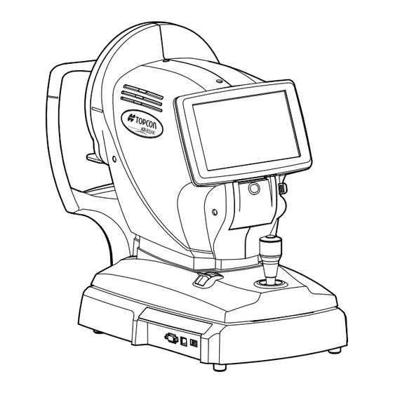
COMPONENTS COMPONENT NAMES Main unit Measuring head Touch panel Printer cover open button Printer cover Measurement button Control lever Base stopper Power supply unit External I/O terminal Chinrest unit Placido ring Measuring window Forehead rest Eye height mark Eye height mark of Chinrest tissue pin measuring window Chinrest... -
Page 14: Operation Method Of Touch Panel
• Do not touch two points on a touch panel simultaneously. • If machine is moved by tapping the touch panel during measurement, it might cause an incorrect measurement. Touch the touch panel softly with a finger. Patient ID TOPCON̲TAROU TOPCON̲TAROU Patient ID Semi Auto -1.25 -1.25... -
Page 15: Function Button (When The Mapping Function Is Off)
Center/Peripheral button ......During KRT measurement, select "C" to measure only the center, or "P" to perform peripheral KRT measurement. R display/L display......Shows the measured eye is R (Right eye) or L (Left eye). The measured eye is framed in orange. Reset button..........Returns the measurement head (the side and the depth direction) to an initial position. -
Page 16: Function Button (When The Mapping Function Is On)
Print out button ........Prints measurement results. Tap the button when no mea- surement data is present to feed the paper. By setting the printer mode to Graphic Printer on the Settings screen, figures showing refractive conditions can be printed. In this case, the printer button changes to Cornea diameter button......Changes to cornea diameter measurement mode. -
Page 17: Monitor Screen
MEASUREMENT SCREEN Alignment mode display Cataract mode display Alignment mark * Barcode reader display Outer alignment mark Patient No./Patient ID Operator ID Number of reading/setting TOPCON̲TAROU TOPCON̲TAROU Number of reading/setting (L, REF) Patient ID Patient ID (R, REF) Semi Auto -1.25 -1.25 -1.25... -
Page 18: Mapping Screen
MAPPING SCREEN Mapping unit display Angle circle Display base curve value BC (ASP) BC (ASP) 4. 20 7.71mm 7.71mm 4. 50 4. 80 R button 5. 10 L button 0.00 0.00 5. 40 5. 70 6. 00 6. 30 Base curve button 6. - Page 19 Mapping step button ........The mapping step can be selected from 0.5 D (0.1 mm), 1.0 D (0.2 mm) 1.5 D (0.3 mm). COMPONENTS...
-
Page 20: Printer Output
Left eye corneal curvature Pupil distance (PD value) (mm) measurement Refractive power measurement result (L) TOPCON logo mark Refractive power measurement result (R) • The reliability factor is defined with integers 1 to 9 in increasing order of reliability. Additionally, if the reliability is high enough, the reliability factor is not shown on the printout. - Page 21 KRT typical value style and KRT print data are R1R2 Barcode Work ID No. Reliability factor Operator ID OID : C mark appears when Patient No./Patient ID the mode is changed Device ID number to the cataract mode manually during a Serial number measurement.
- Page 22 Peripheral measurement mode and mapping data print Peripheral 5-point output mode Peripheral 9-point output mode Radius of curvature around φ6.6 mm and value E (along strong/ weak principal meridians) Recommended value BC of Radius of curvature around φ6.6 mm contact lens. This is added when printing with the mapping print button.
-
Page 23: Printout Format Setting
Date style DMY* DMY* DMY* DMY* Patient No./Patient ID Device ID number Common Serial number Include error data TOPCON logo Message print Input message NULL NULL NULL NULL Graphic print Normal Printer Normal Printer Normal Printer Normal Printer Line space... -
Page 24: Preparations
PREPARATIONS INSTALLATION • When moving the instrument, two people should lift from the bot- tom of the device. One person lifting the device may cause harm to his back or injury by falling parts. • When holding the bottom of the instrument, avoid touching a pro- jection of screws to prevent injuries. -
Page 25: Connecting External I/O Terminals
• Take care not to enter the wrong patient information. It may be mistaken for information from another patient. This product can be connected to a barcode reader via USB. Connect the barcode reader to the input terminal of the instrument. NOTE For questions about connections, contact your TOPCON dealer. PREPARATIONS... -
Page 26: Printer Paper Setting
PRINTER PAPER SETTING • When setting a printer paper, keep a patient's face away from the instrument. Some part of the instrument may touch the patient's lip or nose if the printer cover open button is pressed. • To avoid failure or potential injury, do not open the printer cover while the printer is in operation. -
Page 27: Region Selection Of The Initial Startup
Bring the paper into the center, then close the printer cover. • Please close the printer cover using your right thumb while placing your index and middle fingers on the projecting part which is in reverse side below the printer cover OPEN button. Unexpected movement is avoided when closing the printer cover. -
Page 28: Resetting The Region To Be Used
If resetting the region to be used is required such as by setting the wrong region, perform the follow- ing operation. NOTE If the factory default is carried out, clear the setting information of all users. Tape the button of the Settings TOPCON̲TAROU TOPCON̲TAROU Patient ID Patient ID control panel. Semi Auto -1.25 -1.25... -
Page 29: Recovery From Power Save Status
RECOVERY FROM POWER SAVE STATUS This instrument adopts the power save system for saving electric power. When the machine is not operated for a set time, the touch panel becomes a screensaver. Tap the touch panel, operate the control lever or move the base to the left or the right. In a few seconds, the measurement screen is displayed and measurement is enabled. -
Page 30: Basic Operations
Check that the MEASUREMENT screen is on. Tap the button on the touch panel and select the measurement mode. MEASUREMENT MODE Indication of the but- MEASUREMENT MODE TOPCON̲TAROU TOPCON̲TAROU Patient ID Patient ID ton is changed. Semi Auto REF:Only REF measurement KRT: Only KRT measurement... -
Page 31: Patient Positioning
PATIENT POSITIONING • To avoid injury by moving the instrument, do not press the reset button with the patient's face on the chinrest. • To avoid electric shock, do not touch the external connection ter- minal and the patient at the same time. •... - Page 32 Hold the control lever, pull the main body towards operator side, place the patient's chin on the chinrest and touch patient's forehead to the forehead rest. Adjust the chinrest height by up/down button for chinrest until the eye height mark of the chin- rest reaches the same height as the patient's eye.
-
Page 33: Measurement In Semi-Auto Mode
Semi-Auto mode. If the large sign "A" is not displayed in the button with orange background, it Alignment mode is in other mode. Tap the button to change to Semi-auto mode. TOPCON̲TAROU Patient ID TOPCON̲TAROU Patient ID Semi Auto R1 R1... -
Page 34: Alignment And Measurement
ALIGNMENT AND MEASUREMENT To avoid injury when operating the machine (for measurement and touch panel operation), be careful not to approach the finger to space of movable part. CAUTION Alignment operations are done with the control lever. • The main body position can be fine-adjusted longitudinally and laterally by inclining the con- trol level to each direction. - Page 35 Use the base stopper to release the main body. Hold the control lever and move the main body to the operator side. Operate the control lever laterally and vertically to obtain the target eye in the center of touch panel screen. TOPCON̲TAROU TOPCON̲TAROU Patient ID Patient ID...
- Page 36 Keeping the alignment dot within the alignment mark, slowly move the main body toward the patient. When the main body approaches the target eye, Z alignment arrows appear to the touch panel screen. TOPCON̲TAROU TOPCON̲TAROU Patient ID Patient ID Semi Auto R1 R1...
- Page 37 Measurement operation is not performed while the message is displayed. If this occurs, the operator should tell the patient to open their eyes as wide as possible, or lift the eyelid with care not to push the patient's eye. TOPCON̲TAROU TOPCO TOPCO N̲TAR N̲TA...
-
Page 38: Displaying Measurement Values
DISPLAYING MEASUREMENT VALUES Data of the latest measurement are displayed on the touch panel screen. Figures only: Measurement was done correctly. ERROR: Measurement was not done correctly. For explanation of the messages on the touch panel screen, refer to NOTE "MESSAGE LIST"... -
Page 39: Alignment And Measurement
If the large sign "AS" is not displayed in the button with orange background, Alignment mode it is in other mode. Tap the button to change to Auto shoot mode. TOPCON̲TAROU TOPCON̲TAROU Patient ID Patient ID Auto Shoot R1 R1 R1 R1... - Page 40 TOPCON̲TAROU TOPCON̲TAROU Patient ID Patient ID Auto Shoot R1 R1 R1 R1 R2 R2 R2 R2 A1 A1 A1 A1 Too close TOPCON̲TAROU TOPCON̲TAROU Patient ID Patient ID Auto Shoot R1 R1 R1 R1 R2 R2 R2 R2 A1 A1 A1 A1 Too far TOPCON̲TAROU...
-
Page 41: Displaying Measurement Values
DISPLAYING MEASUREMENT VALUES Data of the latest measurement are displayed on the touch panel screen. Figures only: Measurement was done correctly. ERROR: Measurement was not done correctly. For explanation of the messages on the touch panel screen, refer to NOTE "MESSAGE LIST"... -
Page 42: Measurement In Manual Mode
Alignment mode in Manual mode. If the large sign "M" is not displayed in the button with orange background, Alignment mode it is in other mode. Tap the button to change to Manual mode. TOPCON̲TAROU TOPCON̲TAROU Patient ID Patient ID MANUAL R1 R1... -
Page 43: Displaying Measurement Values
After one eye measuring is finished, pull the control lever forward once, and then slide to the crosswise direction to switch the measured eye. Repeat the same procedure to measure the other eye of the patient in sequence. TOPCON̲TAROU Patient ID TOPCON̲TAROU Patient ID... -
Page 44: Measurement In Peripheral Measurement Mode
"R/ Measurement mode K" or "KRT" large. If the button is displayed as "REF" large, tap to switch to "R/K" or Measurement mode "KRT". TOPCON̲TAROU TOPCON̲TAROU Patient ID Patient ID Semi Auto R1 R1 R1 R1 R2 R2... - Page 45 • It is possible to judge whether effective data can be acquired at each measurement point or not by displaying each square constituting the periphery data mark. : Display valid data : Display invalid data • The display of the periphery data mark is not the last data of the continu- ous measurement, but it indicates whether it is valid or invalid depending NOTE on the typical value.
-
Page 46: Mapping Measurement
"REF" large, tap to switch to "R/K" or Measurement mode "KRT". Check the measurement screen, if the button is (mapping Mapping change function OFF), tap to switch to (mapping function ON). TOPCON̲TAROU TOPCON̲TAROU Patient ID Patient ID Semi Auto R1 R1 R1 R1 R2 R2 R2 R2... - Page 47 R button/L button......Switches mapping screen for right eye or left eye. The selected button L or R is framed in orange. Exit button ..........Exits mapping screen and return to the measurement screen. Mapping display button ......Switches mapping display mode. Mapping: An opaque map is displayed overlaying on the anterior dis- play.
-
Page 48: Print-Out Of Measurement Values
PRINT-OUT OF MEASUREMENT VALUES • To avoid a paper jam in the printer, do not feed the paper if it is partly cut or wrinkled. • To avoid discoloring of the printer paper (particularly the recording area) during storage, use a polypropylene bag and not one containing plasti- NOTE cizer (PVC, etc.). -
Page 49: Measurement Image Observation
MEASUREMENT IMAGE OBSERVATION It is possible to observe the measurement images of REF and KRT each. MEASUREMENT IMAGE OBSERVATION Tap the button after measuring in R/K or KRT mode. TARGET IMAGE TOPCON̲TAROU TOPCON̲TAROU Patient ID Patient ID Semi Auto -1.25 -1.25 -1.25 -1.25... -
Page 50: Displaying All Measurement Data
Normally the latest measurement is displayed, but it is possible to display and confirm all measure- ment data. Measurement data chooses and displays "REF data" and "KRT data". Tap the button of the touch panel. TARGET IMAGE TOPCON̲TAROU TOPCON̲TAROU Patient ID Patient ID Semi Auto -1.25... - Page 51 NOTE When no data is memorized, the data table shows blank. To change "REF data" and "KRT data," tap the button. REF/KRT RIGHT LEFT 7.80 7.75 7.80 7.75 7.80 7.75 7.80 7.75 * 7.80 7.75 7.80 7.75 * 7.80 7.75 7.80 7.75 When the reliability of...
-
Page 52: Clearing Measurement Values
CLEARING MEASUREMENT VALUES Tap the button on the touch panel. ALL CLEAR All measurement values of both eyes are cleared. TOPCON̲TAROU Patient ID TOPCON̲TAROU Patient ID Semi Auto -1.25 -1.25 -1.25 -1.25 - .5 - .5 - .5 - .5 R1 R1... -
Page 53: Optional Operations
• Be sure to verify the input ID to agree with data of a patient or an operator. MEASUREMENT OF CORNEA DIAMETER MEASUREMENT ON THE ACTUAL IMAGE Tap the button. CORNEA DIAMETER TOPCON̲TAROU TOPCON̲TAROU Patient ID Patient ID Semi Auto R1 R1... - Page 54 When the pupil is displayed, moves the measuring head so that the pupil image and alignment dot are at the center of the screen. Using the button (L), move the left positioning bar to the left end of POSITIONING BAR CONTROL the iris from the touch panel side.
-
Page 55: Measurement On The Still Image
MEASUREMENT ON THE STILL IMAGE When KRT measurement values are available, the still image of the measurement is displayed. Follow steps 1 to 3 of "MEASUREMENT ON THE ACTUAL IMAGE" and display the cornea image at the screen center. Press the to display the saved image. -
Page 56: Measurement Of Hard Contact Lens
MEASUREMENT OF HARD CONTACT LENS Confirm that it is in the corneal shape measurement (R/K mode or KRT mode). Alternatively, tap button on the touch panel and select the measurement mode. Measurement mode Place water in the concave part at the tip of the contact lens holder of the attached model eye and affix the contact lens to be measured. -
Page 57: Output Using Rs-232C
OUTPUT USING RS-232C This instrument can output data to a PC, etc. via the RS-232C interface. Connect the interface cable to RS-232C OUT. Refer to "CONNECTING EXTERNAL I/O TERMINALS" on page 23. Set up of data communication settings. For details, refer to "DATA COMMUNICATION (COMM)" on page 65. Perform measurements. -
Page 58: Setting Functions On Setup Screen
Make sure that the power cable is connected. For connection, refer to "CONNECTING POWER CABLE" on page 22. Turn ON the switch. POWER Tap the button on the touch panel. SETTINGS SETTINGS button TOPCON̲TAROU TOPCON̲TAROU Patient ID Semi Auto -1.25 -1.25 -1.25 -1.25 - .5 - .5... -
Page 59: Outline Of Setup Screen Operations
OUTLINE OF SETUP SCREEN OPERATIONS and select the subject of setting. INDEX Operate the button or button, as necessary, and display the page NEXT PAGE BACK PAGE to confirm/change. Tap the button of the item to be changed and find the but- CURRENT CONDITION OPTIONS... - Page 60 TEN-KEY: Tap ten-key on the screen and enter the figure. If there are several windows to enter, tap the window to enter the figure by ten-key. Tap and fix the input value. Enter window KEYBOARD: Tap keyboard on the screen and enter characters. If there are several windows to enter, tap the window to enter the figure by keyboard.
-
Page 61: Returning To The Measurement Screen
RETURNING TO THE MEASUREMENT SCREEN Tap the button. Reuurn The Measurement screen is displayed. TOPCON̲TAROU TOPCON̲TAROU Patient ID Semi Auto -1.25 -1.25 -1.25 -1.25 - .5 - .5 - .5 - .5 R1 R1 R1 R1 R2 R2 R2 R2 7.75 7.75... -
Page 62: List Of Setup Items
LIST OF SETUP ITEMS Setup items are categorized into 6 large indexes. "Initial" ........items related to the initial status after power on "Print" ........items related to output from the internal printer "Comm" ........items related to data output with the external device "LAN".........items related to output using the LAN "Operator ID"... - Page 63 Initial value (Region) Descriptions Options Details VD value (Distance between corneal vertex and eyeglass lens 0.00 rear surface) is set to 0mm (contact lens). VD value (Distance between corneal vertex and eyeglass lens 12.00 rear surface) is set to 12.00mm (eyeglass lens). VD value (Distance between corneal vertex and eyeglass lens ...
- Page 64 Initial value (Region) Descriptions Options Details When turning on the power or moving to the next patient, set the mapping function to OFF. Mapping change When turning on the power or moving to the next patient, Mapping set the mapping function to ON. ...
-
Page 65: Setting Of Internal Printer (Print)
Serial No. is printed. "Error" data is not printed. Include error data "Error" data is printed. TOPCON logo is not printed. TOPCON logo TOPCON logo is printed. Message is not printed. Message print Message is printed. - Page 66 Initial value (Region) Description Options Details Measurement values are printed in terms of Right or Left. Print Layout DATA Measurement values are printed in terms of REF or KRT. VD value (Vertex distance) is not printed. VD value (Vertex distance) is printed. Cylinder sign is not printed.
-
Page 67: Data Communication (Comm)
Options Details Only REF data are output. Output data format Only KRT data are output. All data are output. OLD TOPCON format NEW TOPCON format STD1 TOPCON STD1 format STD2 TOPCON STD2 format Communication Format STD4 TOPCON STD4 format... -
Page 68: Lan Connection (Lan)
Assign IP address manually. IP address setting AUTO Assign IP address automatically. 0.0.0.0 IP address IP address of KR-800PA to output data. 0.0.0.0 Set by keyboard display 0.0.0.0 Subnet mask Subnet mask address of KR-800PA. 0.0.0.0 Set by keyboard display 0.0.0.0... -
Page 69: Maintenance
MAINTENANCE DAILY CHECKUPS USER MAINTENANCE ITEM Item Inspection time Contents • The instrument works properly. Inspection Before using • The objective lens must be free of stain or flaw. • Objective lens Cleaning When the part is stained • Placido Ring •... -
Page 70: Checking The Measuring Accuracy
0.12D and perform measurement. If the measurement result is widely different from the value shown on the model eye, call your dealer or TOPCON at the address on back cover. BRIGHTNESS ADJUSTMENT OF TOUCH PANEL • The touch panel is optimally adjusted when shipped. -
Page 71: How To Clean This Instrument
HOW TO CLEAN THIS INSTRUMENT CLEANING THE FOREHEAD REST AND CHIN REST Wipe the forehead rest and the chin rest with a cloth moistened with a tepid solution of neutral deter- gent for kitchenware. CLEANING THE PLACIDO RING AND THE COVER Do not clean plastic parts with solvents. -
Page 72: Replacing And Ordering Consumable Items
REPLACING AND ORDERING CONSUMABLE ITEMS ORDERING CONSUMABLE ITEMS • When ordering consumable items, tell the product name, product code and quantity to your dealer or TOPCON at the address of back cover. Product name Product code Product name Product code... -
Page 73: Troubleshooting
TROUBLESHOOTING TROUBLE-SHOOTING OPERATIONS MESSAGE LIST OVER-SPH Spherical power exceeds +22D or -25D. Measurement cannot be performed for out of measuring range. OVER-CYL Cylindrical power exceeds ±10D. Measurement cannot be performed for out of measuring range. OVER-R Corneal curvature exceeds 5.00-10.00mm. Measurement cannot be performed for out of measuring range. - Page 74 Patient ID is required. Displayed when the output operation is requested when the setting "Patient ID Please set patient ID. (Mandatory)" is ON but the patient ID is not inputted. Enter the patient ID and then request the output operation. Operator ID is required.
- Page 75 First Octet is 1-223 Range Displayed when the first octet of IP address, default gateway, primary DNS server or secondary DNS server is set to a value out of the specified input range. Enter a value within the input range. Value is irregular.
-
Page 76: Trouble-Shooting Operations
If a problem is suspected, use the following check list. If following instructions does not improve the condition, or if your problem is not included in the list, con- tact your dealer or TOPCON at the address on the back cover. CHECK LIST... -
Page 77: Printer Paper Jam
PRINTER PAPER JAM • When setting a printer paper, keep a patient's face away from the instrument. Some part of the instrument may touch the patient's lip or nose if the printer cover open button is pressed. • To avoid failure or potential injury, do not open the printer cover while the printer is in operation. -
Page 78: Specifications And Performance
SPECIFICATIONS AND PERFORMANCE SPECIFICATIONS AND PERFORMANCE Range of Refractometry Measurement Spherical refractive power: -25 to +22D (0.12D/0.25D steps) Cylindrical refractive power: 0D to 10D (0.12D/0.25D steps) Direction of cylindrical axis: 1° to 180° (1°/5° steps) (where, spherical refractive power + cylindrical refractive power +22D, or spherical refractive power + cylindrical refractive power -25D) -
Page 79: General Information On Usage And Maintenance
• To keep the eye open. • To understand and follow instructions when undergoing an examination. INTENDED USER PROFILE Since the Auto Kerato-Refractometer KR-800PA are medical devices, the operation should be supervised by a physician. ENVIRONMENTAL CONDITIONS OF USE Temperature : 10°C to 35°C... -
Page 80: Environmental Conditions For Packaging In Transportation
ENVIRONMENTAL CONDITIONS FOR PACKAGING IN TRANSPORTATION (Product in its normal transport and storage container as provided by manufacturer) Temperature : -40°C to 70°C Humidity : 10% to 95% Pressure : 700hPa to 1060hPa ELECTRIC RATING Source voltage : 100V- AC, 50-60Hz Power input : 55-90VA SAFETY DESIGNATIONS PER IEC 60601-1 STANDARD... -
Page 81: Operation Principle
This Product Contains a coin cell. You cannot replace batteries by yourself. When you need to replace and/or dispose batteries, con- tact your dealer or TOPCON listed on the back cover. EU Battery Directive NOTE This symbol is applicable for EU members states only. -
Page 82: Electromagnetic Compatibility
Guidance and manufacturer's declaration - electromagnetic emissions The KR-800PA is intended for use in the electromagnetic environment specified below. The customer or the user of the KR-800PA should assure that it is used in such an environment. Emissions test Compliance... - Page 83 Guidance and manufacturer's declaration - electromagnetic immunity The KR-800PA is intended for use in the electromagnetic environment specified below. The customer or the user of the KR-800PA should assure that it is used in such an environment. IEC 60601 Compliance...
- Page 84 Guidance and manufacturer's declaration - electromagnetic immunity The KR-800PA is intended for use in the electromagnetic environment specified below. The customer or the user of the KR-800PA should assure that it is used in such an environment. IEC 60601 Compliance...
-
Page 85: Requirements For The External Device
RF communications equipment and the KR-800PA The KR-800PA is intended for use in an electromagnetic environment in which radiated RF disturbances are controlled. The customer or the user of the KR-800PA can help prevent electromagnetic interference by main- taining a minimum distance between portable and mobile RF communications equipment (transmitters) and the KR-800PA as recommended below, according to the maximum output power of the communications equipment. -
Page 86: Patient's Environment
PATIENT'S ENVIRONMENT When the patient or inspector may touch the devices (including the connecting devices) or when the patient or inspector may touch the person that comes into contact with the devices (including the connecting devices), the patient's environment is shown below. In the patient's environment, use the device conforming to IEC60601-1. -
Page 87: Safety Of Led Product
SAFETY OF LED PRODUCT • Use of controls or adjustments or performance of procedures other than those specified herein may result in hazardous radia- CAUTION tion exposure. • Do not remove the enclosures. LED high-power is radiated. Class of LED product CLASS1 LED PRODUCT LED output M LED (For Measurement) Aperture of LED... - Page 88 LED light source M LED (For Measurement) Output 70mW (CW) (Infrared) Wavelength 870nm Half width 50nm Beam divergence 0.87 rad XY LED (For XY alignment) Output 6mW (CW) Wavelength 950nm Half width 50nm Beam divergence 0.14 rad PLACIDO LED (For Corneal topography) Output 14mW (CW) Wavelength...
-
Page 89: Reference
REFERENCE OPTIONAL ACCESSORIES • Adjustable instrument table AIT-16 The table height can be adjusted to facilitate measurement. Specifications • Dimensions....525(W)x490(D)mm • Table height ....660~880mm • Table size .....490x500mm • Weight ......approx. 23kg • Power consumption..150VA (100-120V, 220-240V) SHAPE OF PLUG Country Voltage/frequency Shape of plug... -
Page 90: Ipa Font License Agreement V1.0
IPA FONT LICENSE AGREEMENT v1.0 The Licensor provides the Licensed Program (as defined in Article 1 below) under the terms of this license agreement (“Agreement”). Any use, reproduction or distribution of the Licensed Program, or any exercise of rights under this Agreement by a Recipient (as defined in Article 1 below) constitutes the Recipient’s acceptance of this Agreement. - Page 91 Period of use: Please inform us of the date of purchase. ● Defective condition: Please provide us with as much detail as possible. AUTO KERATO-REFRACTOMETER KR-800PA USER MANUAL Rev.0 October 17, 2017 Published by TOPCON CORPORATION 75-1 Hasunuma-cho, Itabashi-ku, Tokyo, 174-8580 Japan.
- Page 92 AUTO KERATO-REFRACTOMETER KR-800PA 1023602-01A Printed in Japan 1710-100LW...
Need help?
Do you have a question about the KR-800PA and is the answer not in the manual?
Questions and answers