Table of Contents
Advertisement
THE APPROVAL OF THE CERTIFICATION ENGINEER
©
Druck Limited 2010
This document is the property of Druck Limited and may not, either in part or whole, be copied or otherwise rep roduced,
communicated in any way to third parties, nor stored in any data processing system, without the express written authority of
Druck Limited.
Page 1 of 98
CERTIFICATE RELATED DRAWING
NOT TO BE MODIFIED WITHOUT
APPROVED:
M T CONCANNON
CERTIFICATES:
Baseefa10ATEX0010X
Baseefa10ATEX0012X
IECEx BAS 10.0002X
IECEx BAS 10.0004X
Pressure measurement
for research & industry
Druck Limited
Fir Tree Lane
Groby
Leicester LE6 0FH
England
Tel: 0116 231 7100
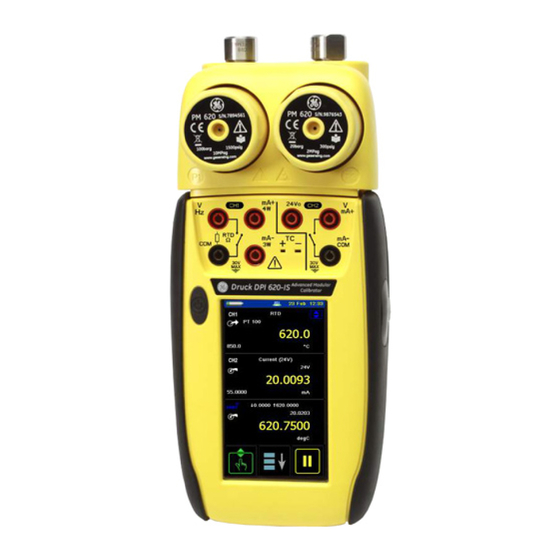
DPI 620-IS
Advanced Modular Calibrator
User Manual
K0460
K0460 Issue 1
Advertisement
Table of Contents

Related Manuals for GE Druck DPI 620-IS


Summary of Contents for GE Druck DPI 620-IS
- Page 1 Pressure measurement for research & industry Druck Limited Fir Tree Lane Groby Leicester LE6 0FH England Tel: 0116 231 7100 CERTIFICATE RELATED DRAWING NOT TO BE MODIFIED WITHOUT THE APPROVAL OF THE CERTIFICATION ENGINEER APPROVED: M T CONCANNON CERTIFICATES: Baseefa10ATEX0010X Baseefa10ATEX0012X IECEx BAS 10.0002X IECEx BAS 10.0004X...
- Page 2 Amendment Record Amendments Iss No Date C/N No Originator Typed Workflow 21/07/10 Robert Lee Robert Lee 149146 New document Approvals Engineering Engineering (Certification) G DOCHERTY M CONCANNON Marketing Technical Communications M SHELTON R LEE Page 2 of 98 K0460 Issue 1...
- Page 3 Print Instructions: K0460 • Finished Size: A5 Portrait (148 x 210 mm) • Print in colour throughout (covers + text), saddle stitched. • Cover to 285 gsm, content to 100 gsm. THIS HARDCOPY IS NOT TO BE USED AS CAMERA COPY. Page 3 of 98 K0460 Issue 1...
- Page 4 Page 4 of 98 K0460 Issue 1...
- Page 5 Measurement & Control Systems Druck DPI 620-IS advanced modular calibrator user manual - K0460...
-
Page 6: Quick Reference Data
Issue 1 Quick reference data A1.1 DPI 620-IS: Channel 1 (CH1) Measure (M) / Source (S) / Power (P) ±30 V (M) ±55 mA (M) 0 to 12 V (S) 0 to 24 mA (S) ±2000 mV (M) 8 RTDs (M/S): Pt1000, Pt500, Pt200, Pt100(385), 0 to 2000 mV (S) Pt50, D 100, Ni 100, Ni 120 0 to 4000 Ω... -
Page 7: Safety
Issue 1 Safety Before using the instrument, read and understand all the related data. This includes: the applicable local safety procedures, this publication, and the instructions for any accessories/options/equipment. General warnings WARNING • It is dangerous to ignore the specified limits for the instrument or its related accessories. - Page 8 Issue 1 • It is dangerous to attach an external source of pressure to a PM 620-IS series pressure station. Use only the specified mechanisms to set and control the pressure in the pressure station. Cautions To prevent damage to the display, do not use sharp objects on the touch-screen.
-
Page 9: Overview
Issue 1 Overview The intrinsically safe, advanced modular calibrator (AMC) is part of a set of hand-held modules that can be quickly put together to include a wide range of calibrator functions. Advanced modular calibrator, DPI 620-IS (this user manual): This is a battery-powered instrument for electrical measure and source operations and HART®... - Page 10 Issue 1 Software (this user manual): The DPI 620-IS calibrator includes the following software: • • documenting software HART® communications software Other accessories and options: For part numbers (P/N), refer to Section 1.4 (Accessories). Summary of This table gives a summary of the available functions with the DPI 620-IS calibrator.
-
Page 11: About This Manual
Issue 1 DPI 620-IS - Calibrator functions (Continued) Function ® HART (Highway Addressable Remote Transducer) communications software to set up and calibrate devices that use the HART field communications protocol. Other functions: Hold, maximum/minimum/average, filter, tare, adjustable backlight, alarm indication (on the display), automatic power off. * Refer to the datasheet ** Optional item †... - Page 12 Issue 1 viii About this manual K0460 - [EN] English...
-
Page 13: Table Of Contents
Issue 1 Table of Contents Quick reference data ............ii Trademarks . - Page 14 Issue 1 2.9 Measure and source operations........2-13 2.9.1 Set the Process options (measure) .
- Page 15 Issue 1 Chapter 6: Datalog operation 6.1 Introduction ............6-1 6.2 Set-up .
- Page 16 Issue 1 Chapter 11: General specification 11.1 Introduction ............11-1 Customer service.
-
Page 17: Chapter 1: Instrument Parts, Accessories And Options
Chapter 1: Instrument parts, accessories and options 1.1 Introduction This chapter gives a description of the different parts of the instrument and the accessories/options available. 1.2 The instrument On or off button. Refer to “Quick Reference”. Connectors for Channel 1 Connectors channel 2 Connector. -
Page 18: Issue
Issue 1 : USB mini Type B connector for communication with a computer. Figure 1-3: The USB connector Cover for the USB connector (Figure 1-3). For IP65, press it fully into the recess over the connectors. Two connection points to attach the pressure module carrier (MC 620-IS);... -
Page 19: The Display
Issue 1 1.3 The display This is a OLED with a colour display with a touch-screen. To make a selection, lightly tap on the applicable display area with a finger; see Section 2.7 (Display operation). Status bar: This includes: a. Battery indicator b. -
Page 20: Accessories
Issue 1 1.4 Accessories 1. IO620IS-CHARGER 2. IO620-IS BATTERY. Ni-MH battery 3. 209-539. Set of six electrical test leads 4. K0461. Safety and quick reference guide 5. UD-0004. CD with the user manual 6. IO620IS CRADLE Figure 1-7: Accessories included 7. - Page 21 Issue 1 [EN] English - K0460 Instrument parts, accessories and options 1-5...
- Page 22 Issue 1 1-6 Instrument parts, accessories and options K0460 - [EN] English...
-
Page 23: Chapter 2: Prepare The Instrument
Chapter 2: Prepare the instrument 2.1 Introduction This chapter gives a description of these items: • the initial checks and procedures • the available power options • the battery and related procedures (install and charge) • the start-up procedures • the menu structure and options •... -
Page 24: The Battery
For operating conditions, see Table 11-1. • Charge the GE specified battery in a safe area, using the GE supplied charger and cradle. • To prevent battery leakage or heat generation, only use the battery charger and cradle in the temperature range 0 to 40°C (32 to 104°F). -
Page 25: Charge The Battery
Issue 1 2.5.3 Charge the battery Fully-charge the battery, using the charger and cradle, in a safe area. • The battery pack [a] (part number: IO620IS – Battery) will be partly-charged, it is recommended to fully charge the battery pack before using the instrument: •... -
Page 26: Operating Time
Issue 1 2.5.5 Operating time Operation Battery duration Continuous operation (measure) > 10 hours Continuous operation (measure and > 6 hours source with loop power on) These are typical operating times for a new, fully-charged Ni-MH battery pack with these settings: •... -
Page 27: Change Items In A List
Issue 1 2.7.1 Change items in a list To change an item in a list, you have these options: • tap on the item you want to use • ▲ ▼ tap on the button • tap on one of the horizontal bars beside the list (if applicable). -
Page 28: Enter Text
Issue 1 2.7.3 Enter text There are alphanumeric key-pad displays for these items: • Captions; see Section 2.8.4 (maximum: 15 characters; all characters permitted) • Filenames (maximum: 10 characters; no special characters) 1. Tap in the applicable characters. 2. To accept the data and go back to the previous display, tap on the completed text in the data entry box. -
Page 29: Menu Sequence
Issue 1 2.8 Menu sequence Section 2.8.1 Section 2.8.2 Chapter 6 † Chapter 7 Section 2.10 † Normally, this is only necessary for versions with the Windows CE operating system, Touch Screen enables the screen to be calibrated and re-centred. [EN] English - K0460 Prepare the instrument 2-7... -
Page 30: Procedure To Set The Basic Operations
Issue 1 2.8.1 Procedure to set the basic operations: Description Configuration Sets the power off automatically after the specified Timeout period. To save the battery power, set this to On. Status: On or Off Timeout: 00:02:00 to 01:00:00 hours:minutes:seconds (hh:mm:ss) Sets the backlight. -
Page 31: Procedure To See The Instrument Status
Issue 1 2.8.2 Procedure to see the instrument status Status Configuration The date of the next calibration. Charging or battery-powered, and the amount of charge in 1% increments. The amount of memory available (in MB and as a % of the total on the device): SD Card (internal). 2.8.3 Procedures to make Task selections When first using the calibrator, there are default measure and source... - Page 32 Issue 1 c. * Pressure function (P1): for the PV 62x-IS pressure Note: * Observed (Only stations, refer to user manual - K0462; for the MC 620-IS available as a source module carrier, see Chapter option). Use this option to make a manual record of d.
-
Page 33: Set A Function
Issue 1 2.8.4 Set a function This example shows the sequence to set the Channel 1 (CH1) function. It is a similar procedure for other functions. Select the function list Task Settings Channel Settings (Measure or Source) Measure Source Select Function Channel Settings Task Settings Section 2.8.5... -
Page 34: Set The Units
Issue 1 2.8.5 Set the units If a function has alternative units, another unit can be set. If there are no alternatives, the area is shown grey. Task Settings Channel Settings Channel Settings Task Settings 2.8.6 Set up a utility: Maximum/Minimum/Average example This example shows the sequence to set the Max/Min/Avg utility. -
Page 35: Measure And Source Operations
Issue 1 2.9 Measure and After setting the measure and source functions required on the display (see Section 2.8.3), these procedures can be set: source operations • If necessary, change the Process for the CH1 and/or CH2 measure functions (item ) including: Tare, Alarm, Filter, Flow, Scaling;... -
Page 36: Set The Process Options (Measure)
Issue 1 2.9.1 Set the Process options (measure Note: Section 2.7 (Display operation) shows how to set and change the values on the display. Tare Use Tare to set a temporary value for zero. This makes an adjustment to all subsequent readings on the display. Set On or Off. - Page 37 Issue 1 Filter: Set the Band and the Time Constant for the low pass filter: Set On or Off. Set the band (%FS). See Definitions. Set the time constant. See Definitions. Previous: Back one display. Home: Back to start. Definitions Band: The filter compares each new value with the previous value.
-
Page 38: Set The Automation Options (Source)
Issue 1 Scaling: Set On or Off Set a scale for Point 1 and Point 2. Set a label name. Previous: Back one display. Home: Back to start. 2.9.2 Set the Automation options (source Note: Section 2.7 (Display operation) shows how to set and change the values on the display. -
Page 39: Set The Observed Settings (Source)
Issue 1 Percent Step Description Process: Percent Step; Values to set: Low, High, Step Size (%FS), Dwell, Auto Repeat (On/Off). Use these buttons to change the value manually by the specified Step Size. Use the start and stop buttons to change the value automatically by the specified Step Size. -
Page 40: The Advanced Menu Options
Issue 1 2.10 The Advanced The Advanced menu provides settings and use of options: menu options • • Settings Calibration • • Files Options Hart On or Off; see Chapter 8. Standards sets IPTS 68 or ITS 90; see Chapter 3 Section 2.10.1. -
Page 41: Advanced Setup Options
Issue 1 Menu to upgrade the To use the most up-to-date software and firmware on the DPI 620-IS software and DPI 620-IS calibrator, visit the GE website: firmware www.gesensinginspection.com Follow the website instructions, use this menu to upgrade: • Connect the instrument to be upgraded to a PC. Copy the files to the instrument’s storage memory (make sure the... - Page 42 Issue 1 2-20 Prepare the instrument K0460 - [EN] English...
-
Page 43: Introduction
Issue 1 Chapter 3: Electrical operations 3.1 Introduction This section gives examples of how to connect and use the instrument for these operations: • To measure and source electrical values. Before starting: • Read and understand the “Safety” section. • Do not use a damaged instrument. -
Page 44: Example Procedure: Measure Or Source Current
Issue 1 • If necessary, change the Process for the CH1 and/or CH2 measure functions: item This includes: Tare, Alarm, Filter, Flow, Scaling; see Section 2.9.1. There are more optional Settings for the TC, Frequency, and RTD functions. • If necessary, change the Automation options for the CH1 and/or CH2 source functions: item This includes: Nudge, Span Check, Percent Step, Defined Step, Ramp;... -
Page 45: Example Procedure: Measure Dc Voltage
Issue 1 1. Set the applicable software options; see Section 3.2.1 (Procedure overview). 2. Complete the electrical connections and continue with the measure or source operation. 3. Source only (Automation): Set the applicable output value; Section 2.9.2. 3.2.3 Example procedure: Measure DC voltage These examples (A and B) show Channel 1 (CH1) set-up to measure a DC voltage. -
Page 46: Example Procedure: Measure Or Source Frequency Signals
Issue 1 Source DC millivolts on channel 1 (CH1) Range: 0 to 2000 mV (DC) Automation: Nudge (Section 2.9.2) 1. Set the applicable software options; see Section 3.2.1 (Procedure overview). 2. Complete the electrical connections. 3. To continue, set the applicable output value; see Section 2.9.2. - Page 47 Issue 1 3. If necessary, change the Trigger Level (Settings) continue with the measure operation. Values to set: Mode (Automatic/Manual); Manual Level (trigger level value) Example 1. Set the applicable software options; see Section 3.2.1 (Procedure overview). 2. Complete the electrical connections. 3.
-
Page 48: Example Procedure: Measure Or Simulate An Rtd (Or Resistance)
Issue 1 3.2.7 Example procedure: Measure or simulate an RTD (or Resistance) These examples (A and B) show Channel 1 (CH1) set-up to measure or simulate an RTD. A 4-Wire configuration gives the best accuracy; a 2-Wire configuration has the lowest accuracy (4-Wire RTD shown). -
Page 49: Example Procedure: Measure Or Simulate A Thermocouple (Or Tc Mv)
Issue 1 3. If necessary change the Source Settings and continue with source operation. Automation: Set the applicable output value; see Section 2.9.2. Values to set: RTD Type (Set the applicable RTD); see Table A1 (front cover) for the available options. 3.2.8 Example procedure: Measure or simulate a thermocouple (or TC mV) These examples (A and B) show Channel 1 (CH1) set-up to measure or simulate a thermocouple temperature. -
Page 50: Example Procedure: Switch Test
Issue 1 3. If necessary change the Settings and continue with the measure operation. Values to set: TC Type (Set the applicable TC). CJ compensation (Mode: Automatic/Manual). Automatic uses the internal cold junction. Use Manual mode for an external cold junction. CJ Value. - Page 51 Issue 1 1. Set the applicable software options; see Section 3.2.1 (Procedure overview). This example shows one function: • Thermocouple (TC) is set to source a temperature. The Utility is set to Switch Test. The Automation is set to Ramp; Section 2.9.2.
-
Page 52: Error Indications
Issue 1 3.3 Error indications If the display shows <<<< (under range) or >>>> (over range): • Make sure that the range is correct. • Make sure that all the related equipment and connections are serviceable. <<<<< Under range: The display shows this symbol for this condition: Reading <... -
Page 53: Chapter 4: Pressure Indicator Operation (Mc 620-Is)
Chapter 4: Pressure indicator operation (MC 620-IS) 4.1 Introduction This section gives examples of how to connect and use the instrument to measure pressure with the module carrier (MC 620-IS) and the applicable pressure modules (PM 620-IS). To measure pressure with the IDOS UPM, refer to Chapter To make a fully integrated pressure calibrator instrument with one of the three pressure stations, refer to the user manual for... -
Page 54: Assembly Instructions
Issue 1 4.2.1 Assembly instructions Step Procedure Align the two slots (a) on the calibrator with the two posts (b) on the module carrier. When the posts are fully engaged in the slots, tighten the two screws until they are hand-tight. Attach one or two PM 620-IS modules with the correct range and type. -
Page 55: Measure Pressure
Issue 1 Step Procedure Re-attach the adaptor to the MC 620-IS carrier and tighten it until it is hand tight only. 4.4 Measure When the pressure indicator assembly is complete (Section 4.2.1), use the menus to set-up the necessary pressure operations. -
Page 56: Set-Up A Leak Test
Issue 1 • When all the software selections are complete, make the applicable pressure and electrical connections. Examples: Measure pressure (Section 4.4.4). 4.4.2 Set-up a Leak Test 1) Set the Utility Set the Utility to Leak Test (Section 2.8.6). 2) Set the Leak Test When setting the Utility to Leak Test, set these options: options Wait Time: The time before the test starts in... -
Page 57: Set The Pressure Module To Zero
Issue 1 4.4.3 Set the pressure module to zero Use this option to write a new zero pressure value to the pressure module. The sensor adjustment is permitted if it obeys this condition: Adjustment ≤ 10% FS positive pressure value (for the Sensor) Note: To make a temporary adjustment for zero, use the Tare function;... -
Page 58: Error Indications
Issue 1 1. Assemble the pressure indicator with the correct PM 620-IS modules; see Section 4.2.1. 2. Set the applicable software options; see Section 4.4.1 (Procedure overview). This example shows two pressure functions: • Pressure functions P1 and P2 are set-up. 3. -
Page 59: Chapter 5: Instrument Communications
Chapter 5: Instrument communications 5.1 Introduction This chapter gives a description of these items: • the procedures to connect the instrument to a computer with the optional USB mini Type B cable. For a full list of optional accessories, refer to Section 1.4. - Page 60 Issue 1 5-2 Instrument communications K0460 - [EN] English...
-
Page 61: Chapter 6: Datalog Operation
Chapter 6: Datalog operation 6.1 Introduction This section gives examples of how to log measurements with time and date over a set time period or on a key press. Logged data is stored in a user defined file. The instrument logs all the tasks currently enabled. - Page 62 Issue 1 Recall Log Playback Filename recalls data by filename from the list. File details shows file name, start time and number of points. Start begins playback of the selected file by pressing the Pause/Play key. Press and hold the Pause/Play key for at least two seconds to reverse sequence.
-
Page 63: Data Logging
Issue 1 6.3 Data Logging To data log: To log measurements made by the instrument, set the required tasks in Task Settings. Select Configuration and select Data Logging. Select Filename and enter a name using the three-page screen alpha/numeric key-pad. Select Trigger and either a time (Periodic) or key press (play/pause). - Page 64 Issue 1 6-4 Datalog operation K0460 - [EN] English...
-
Page 65: Chapter 7: Documenting Functions
Chapter 7: Documenting functions 7.1 Introduction This section gives examples of the documenting functions available with the DPI 620-IS calibrator. There are two options: Analysis (Section 7.2): This function compares the data from two Channels on the DPI 620-IS calibrator: the device under test (DUT) and a reference instrument. -
Page 66: Run A Procedure
Issue 1 Input and Reference Channel type : Input or Reference options Scaling (Input only): Values for Reference High and Low and Input High and Low. This sets the scale for the Analysis function. Error Type (Input only): % Span or % Rdg (Reading) Linearity (Input only): Linear or Square Root Tolerance... -
Page 67: Chapter 8: Hart ® Device Operations
® Chapter 8: HART device operations 8.1 Introduction The DPI 620-IS calibrator can be used to communicate with ® protocol: devices that use the HART The Universal and Common Practice commands specified in • ® HART revision 5 to 7. ®... - Page 68 Issue 1 ® First steps Set-up the HART device, if loop power required, use CH2 for • current (24V), see section 14. If the loop is already powered and there is an external HART • resistor turn off channel 2. Connect the channel 2 mA+ and mA- connections across the external HART resistor.
- Page 69 Issue 1 Variables Launches a data entry screen Methods Only a single tap on the screen is required to open any item in black or open any folder. Terminology = Digital Value of Primary Variable (i.e. this is the parameter that the transmitter measures - pressure, current, voltage).
- Page 70 Issue 1 Method Any item that has got a method icon • executes a method window to prompt with on-screen instructions for performing a test or calibration. Menu Bar - device connection - pressing this allows the user to connect to a transmitter. - software version - pressing this allows the user to identify the DK0397 software version.
- Page 71 Issue 1 Self-test To confirm that the transmitter is functioning • correctly, navigate through the menus to the self-test method button: Press the self-test button. • Press OK and the self-test executes. • To confirm that the transmitter is functioning •...
- Page 72 Issue 1 Type the Analogue value of Primary Variable mA • current (actual calibrated value) into the box using the key-pad and then press Set. Repeat this process with 20 mA selected. This will accurately calibrate the transmitter’s output 4 to 20 mA loop current.
-
Page 73: Hart Connections
Issue 1 Preferences Selecting the icon allows the changing of the poll address, • short tag or long tag of the transmitter. The DPI 620-IS is set by default to use Poll Address 0 (zero) only. This can be changed by selecting the appropriate search radio button or by entering the tag name in the search field. -
Page 74: External Loop Power
Issue 1 ® 2. Set-up the HART device, if loop power required, use CH2 for current (24V). ® If the loop is already powered and there is an external HART resistor, turn off CH2. Connect CH2 mA+ and mA- connections ®... -
Page 75: Communicator Attached To A Network
Issue 1 ® Turn on the internal HART resistor. This can be selected by pressing icon. 6. Complete the electrical connections and continue with the ® HART menu operation. 8.3.3 Communicator In this example, the calibrator connects directly to a network. attached to a There must be a 250Ω... -
Page 76: Failed To Find Device
Issue 1 8.4 Failed to find a The following is a checklist of what to do. device When using the DPI620-IS to supply power, make sure that the • ® internal HART resistor is turned on. Check the preferences option and set this to find first, then •... -
Page 77: Chapter 9: Maintenance Procedures
Chapter 9: Maintenance procedures 9.1 Introduction This section gives procedures to maintain the instrument in a good condition. Return the instrument to the manufacturer or an approved service agent for all repairs. Do not dispose of this product as household waste. Use an approved organisation that collects and/or recycles waste electrical and electronic equipment. - Page 78 Issue 1 9-2 Maintenance procedures K0449 - [EN] English...
-
Page 79: Chapter 10: Calibration Procedures
Chapter 10: Calibration procedures 10.1 Introduction Note: GE can provide a calibration service that is traceable to international standards. Return of the instrument to the manufacturer (recommended) or an approved service agent for calibration. When using an alternative calibration facility, make sure that it uses these standards. -
Page 80: Selection Sequence
Issue 1 Table 10-1: Calibration equipment (Continued) Function Calibration equipment (ppm = parts per million) Resistance (measure) (source) (CH1) Standard 0Ω resistor An ohmmeter or an RTD measurement system with the Standard resistor (Ω): 100, 200, 300, specified excitation currents; see 400, 1k, 2k, 4k Table 10-11. -
Page 81: Procedures (Ch1/Ch2): Current (Measure)
Issue 1 When the calibration is complete, set the next calibration date; Section 2.10.1 (Advanced: Calibration options). 10.4 Procedures 1. Connect the applicable calibration equipment specified in Table 10-1; for example: see Section 3.2.2 (Example (CH1/CH2): Current procedure: Measure or source current). - Page 82 Issue 1 3. Use the calibration menu (Section 10.3) to do a two-point calibration (Zero and FS): • CH1 (one range): 24 mA. • CH2 (two ranges): -24 mA and 24 mA. 4. To make sure the calibration is correct, select the applicable Current (source) function;...
-
Page 83: Procedures (Ch1/Ch2): Dc Mv/Volts (Measure)
Issue 1 10.6 Procedures 1. Connect the applicable calibration equipment in Table 10-1; for example: see Section 3.2.3 (Example procedure: (CH1/CH2): DC Measure DC voltage). mV/Volts (measure) 2. Let the equipment get to a stable temperature (minimum: 5 minutes since the last power on). 3. -
Page 84: Procedures (Ch1 Mv (Measure)/Volts (Source)
Issue 1 10.7 Procedures (CH1 1. Connect the applicable calibration equipment in Table 10-1; Table 10-5: Voltage (measure) error limits mV (measure)/Volts Source Applied Calibrator Permitted uncertainty (V) DPI 620-IS error (V) ±30 0.00052 0.0021 ±21 0.0004 0.0018 ±20 0.00031 0.0009 ±10 0.00016... -
Page 85: Procedures (Ch1): Frequency (Measure/Source)
Issue 1 Table 10-7: Voltage (source) error limits Source Calibrator Permitted uncertainty (V) DPI 620-IS error (V) 0.000004 0.00042 0.000010 0.0006 0.000018 0.00078 0.000027 0.00096 0.000036 0.0011 10.8 Procedures It is only necessary to do one frequency calibration; use the measure function or the source function. - Page 86 Issue 1 3. Set-up the equipment with these conditions: Frequency meter: Gate time = one second DPI 620-IS: Waveform = Square; Amplitude = 10 V; Frequency = 990 Hz 4. Use the calibration menu (Section 10.3) to do a one-point calibration then do the calibration checks (step Calibration check...
-
Page 87: Procedures (Ch1): Frequency Amplitude (Source)
Issue 1 10.9 Procedures 1. Connect the applicable calibration equipment in Table 10-1; for example: see Section 3.2.8 (Example procedure: (CH1): Frequency Measure or source frequency signals), example B. amplitude (source) 2. Let the equipment get to a stable temperature (minimum: 5 minutes since the last power on). -
Page 88: Procedures (Ch1): Resistance (Measure)
Issue 1 10.10 Procedures 1. Let the equipment get to a stable temperature (minimum: 5 minutes since the last power on). (CH1): Resistance (measure) 2. Use the calibration menu (Section 10.3) to do a two-point calibration for each range. • Range: 0-400Ω... -
Page 89: Procedures (Ch1): Resistance (Source)
Issue 1 10.11 Procedures 1. Connect the applicable calibration equipment in Table 10-1; for example: see Section 3.2.9 (Example procedure: (CH1): Resistance Measure or simulate an RTD (or Resistance)), example B. (source) 2. Let the equipment get to a stable temperature (minimum: 5 minutes since the last power on). -
Page 90: Procedures (Ch1): Tc Mv (Measure Or Source)
Issue 1 10.12 Procedures 1. Connect the applicable calibration equipment in Table 10-1; for example: see Section 3.2.10 (Example procedure: (CH1): TC mV Measure or simulate a thermocouple (or TC mV)). (measure or source) 2. Let the equipment get to a stable temperature (minimum: 5 minutes since the last power on). -
Page 91: Procedures (Ch1): Cj (Measure)
Issue 1 10.13 Procedures Note: Do the TC mV (measure) calibration (Section 10.12) before the cold junction calibration. (CH1): CJ (measure) 1. Connect the applicable calibration equipment in Table 10-1; for example: see Section 3.2.10 (Example procedure: Measure or simulate a thermocouple (or TC mV)), example A. -
Page 92: Procedures (Ch1): Pressure Indicator Modules (Pm 620-Is)
Issue 1 10.14 Procedures: 1. Assemble the pressure indicator with the necessary PM 620-IS modules and connect the instrument to the Pressure indicator pressure standard; see Section 4.4.4 (Example procedure: modules (PM 620-IS) Measure pressure). 2. Let the equipment get to a stable temperature (minimum: 60 minutes since the last power on). - Page 93 Issue 1 5. Make sure the error is in the specified limits; see the tables for Gauge Ranges or Absolute Ranges given in the datasheet (supplied on the CD: P/N UD-0002); use the values in column “Total uncertainty ... “. The specified values include an allowance for temperature changes, reading stability for one year, and the uncertainty of the standard used for calibration.
- Page 94 Issue 1 10-16 Calibration procedures K0460 - [EN] English...
- Page 95 Pressure Equipment Directive - Class: Sound Engineering Practice (SEP) Approved CE Marked Battery power NiMH battery (GE Part number: IO620IS-Battery) Capacity: 4000 mAh; Nominal voltage: 3.6 V Charge temperature: 0 to 40°C (32 to 104°F) If the charger senses the temperature is outside this range, it stops charging.
- Page 96 Issue 1 11-2 General specification K0460 - [EN] English...
- Page 97 Customer service Visit our web site: www.gesensinginspection.com...
Need help?
Do you have a question about the Druck DPI 620-IS and is the answer not in the manual?
Questions and answers