Table of Contents
Advertisement
Quick Links
Advertisement
Table of Contents

Related Manuals for GE Druck DPI 880


Summary of Contents for GE Druck DPI 880
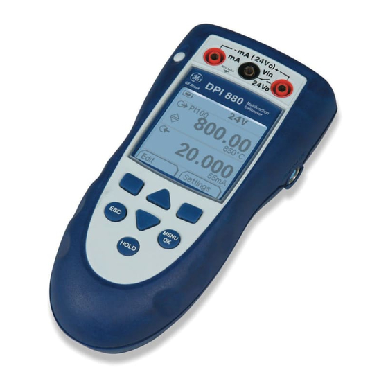
- Page 1 GE Industrial Sensing Druck DPI 880 Multi-function calibrator User manual - K405...
- Page 2 K405 Issue 1...
-
Page 3: Table Of Contents
Table of Contents Introduction The DPI 880 Multi-function Calibrator is part of the Introduction ................. 1 Druck DPI 800 series of hand held instruments. Safety ..................1 The DPI 800 series uses Intelligent Digital Output Sensor Safety - Marks and symbols on the instrument ....2 (IDOS) technology to give instant plug and play To start .................. -
Page 4: Safety - Marks And Symbols On The Instrument
Safety (Continued) To start - Items on the display Item Description • To prevent electrical shocks or damage to the Task indication for the switch test. instrument, do not connect more than 30V between = switch closed the terminals, or between the terminals and the = switch open ground (earth). -
Page 5: To Start - Prepare The Instrument
To start - Prepare the instrument To start - Select a task (Measure and/or supply) Before you use the instrument for the first time: When the instrument is set up (Table 1), use the task selection menu to select the applicable task. •... -
Page 6: To Start - Set Up The Settings
Table 3: Menu options - Task selections Table 4: Menu options - Settings (Input) (Dual Function, area Options Description (If applicable) Options Description (If applicable) ... Units Pressure Units (UPM only). If you select an IDOS task (Table 2/3). Select one of the fixed units of White button = A Dual Function is set. -
Page 7: Operation
Operation Table 5: (Part of table) Menu options - Settings (Output) This section gives examples of how to connect and use the Options Description (If applicable) instrument. Before you start: To select and set up values for the “Span Check” •... -
Page 8: Operation - Measure/Supply Ma
Operation - Measure/supply mA To measure/supply a current: Maximum: 30V 1. Connect the instrument (Figure 1, 2 or 3) and, if necessary, adjust the Set Up (Table 1). 2. Select the task from the task selection menu (Table 2/3). Note: Use the Dual Function area ( ) to do two operations at the same time. -
Page 9: Operation - Measure/Supply Hz Or Pulses
For an input, the display shows the condition of the frequency gate: 0 to ±30V Gate open (measurement starts) Gate closed (measurement is waiting for the next rising edge of the cycle) Fast cycle Operation - RTD/Ohms connections In the examples that follow 2W, 3W, and 4W identify the 2, 3, and 4-wire connections for a RTD or resistance. -
Page 10: Operation - Thermocouple (Tc) Connections
°C Settings Settings Settings a) °C or °F (Input) b) mV (Input) Edit Settings Edit Settings a) RTD °C or °F b) Ohms (Ω) Figure 8: Example configuration - To simulate the temperature or resistance Operation - Thermocouple (TC) connections Attach the TC wires to the applicable TC mini-connector (Figure 9). -
Page 11: Operation - Transmitter Calibration
Operation - Transmitter calibration Operation - Switch test To calibrate a transmitter: To do tests on a switch: 1. Connect the instrument (Figure 10/11) and, if 1. Connect the instrument (Figure 12) and, if necessary, necessary, adjust the Set Up (Table 1). adjust the Set Up (Table 1). -
Page 12: Operation - Upm Pressure Measurements
Operation - UPM Pressure measurements Read all the instructions supplied with the UPM and then use the specified procedures to connect it (Figure 13/14). Settings Start Settings Settings a) Pressure b) Leak test Figure 14: Example configuration - To measure pressure Figure 13: Example configuration - Pressure measurement and temperature with a UPM... -
Page 13: Maintenance
Set Up (Table 1) Calibration Calibration Display: Enter Menu: Note: GE can provide a calibration service that is traceable Calibration PIN Select Channel to international standards. We recommend that you return the instrument to the manufacturer or an approved service agent for calibration. -
Page 14: Calibration - Procedures: Ma Input
Calibration - Procedures: mA input Table 11: mA output error limits Output Calibrator Permitted 1. Connect the instrument to the calibration equipment error DPI 880 error (Figure 3). (mA) (mA) 2. Let the equipment get to a stable temperature 0 (Short circuit) 0.001 (minimum: 5 minutes since the last power on). -
Page 15: Calibration - Procedures: Mv/Volts Output
Calibration - Procedures: mV/Volts output 5. To make sure that the calibration is correct, set up the equipment to do one of these calibration checks: 1. Connect the instrument to the calibration equipment (Figure 4). • Hz input calibration check (Figure 6): 2. -
Page 16: Calibration - Procedures: Rtd (Ohms) Input
Calibration - Procedures: RTD (Ohms) input Table 18: RTD (Ohms) output error limits 1. Let the equipment get to a stable temperature Ohms Excitation Calibrator Permitted (Ω) (mA)* error DPI 880 error (minimum: 5 minutes since the last power on). (Ω) (Ω) 2. -
Page 17: Specification Data
Specification data Specification - Electrical (A1 - Item 10) All accuracy statements are for one year. Range (Measure): 0 to ±55 mA 0 to ±120 mV 0 to 4000Ω* 0 to ±30 V Specification - General Accuracy: Measure mA 0.02% of reading + 3 counts Languages English [Default] Accuracy: Measure mV... -
Page 18: Specification - Temperature Ranges (Tc)
Specification - Temperature ranges (TC) Thermocouple type Standard Range °F Range °C Accuracy °F * Accuracy °C * IEC 584 -454 to -328 -270 to -200 IEC 584 -328 to 2502 -200 to 1372 IEC 584 -346 to 2192 -210 to 1200 IEC 584 -454 to... -
Page 19: Customer Service
Customer Service Visit our web site: www.gesensing.com...