GE Druck DPI 610 User Manual
Portable pressure calibrator series
Hide thumbs
Also See for Druck DPI 610:
- User manual (18 pages) ,
- User manual (95 pages) ,
- Service manual (81 pages)

Related Manuals for GE Druck DPI 610


Summary of Contents for GE Druck DPI 610
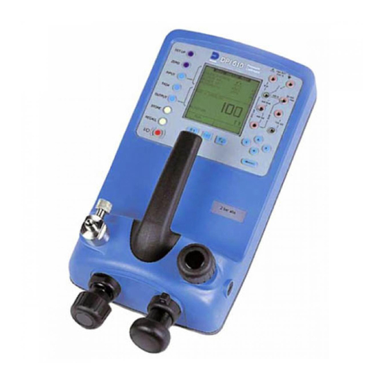
- Page 1 Sensing Druck DPI 610/615 Portable Pressure Calibrator Series User manual - K415...
- Page 3 Language To select the manual in an available language go to: //www.gesensing.com/toolsupport/manuals.htm Français Pour choisir le manuel dans une langue disponible allez: //www.gesensing.com/toolsupport/manuals.htm Deutche Um das Handbuch in einer vorhandenen Sprache vorzuwählen gehen Sie: //www.gesensing.com/toolsupport/manuals.htm Italiano Selezionare il manuale in una lingua disponibile vada: //www.gesensing.com/toolsupport/manuals.htm Español A seleccionar el manual en una lengua disponible vaya:...
- Page 4 Safety The manufacturer has designed this equipment to be safe when operated using the procedures detailed in this manual. Do not use this equipment for any other purpose than that stated. This publication contains operating and safety instructions that must be followed to ensure safe operation and to maintain the equipment in a safe condition.
- Page 5 Specification Safe working pressure 20 bar range (300 psi) 1.75 x full-scale 350 bar range (5000 psi) 1.2 x full-scale 400 bar range (6000 psi) 1.5 x full-scale All other ranges 2 x full-scale Accuracy Combined non-linearity, hysteresis and repeatability ±70 mbar range (2 inHg) 0.05% F.S.
- Page 6 Specification (contd.) Display Size: 60 x 60 mm (2.36” x 2.36”) LCD Graphics Reading ±99999, update rate 2 readings/sec Environment Operating Temperature: -10°C to 50°C (+14°F to 122°F) Calibrated Temperature: -10°C to 40°C (+14°F to 104°F) Storage Temperature: -20°C to 60°C (-4°F to 140°F) Calibration Temperature: 21°C ±2°C (70°F ±4°F) Sealing...
-
Page 7: Table Of Contents
Introduction General Description of Procedures Summary of Functions Using the Guide OPERATOR CONTROLS DISPLAY HARD KEY FUNCTIONS SOFT KEYS CURSOR KEYS ELECTRICAL CONNECTIONS Getting Started Fitting Batteries Switching On Change Pressure Units Voltage and Current Measurement Typical Calibration Set-up (Pressure to Voltage) Zero Display Reading Task Selection Task Key... - Page 8 Advanced Task General Select Input Ambient Temperature Measurement Process Functions Tare Process Function Min/Max Process Function Filter Process Function Flow Function % Span Select Output Electrical Outputs (Loop Power) mA Step mA Ramp mA Value 24 Volt Define New Task Clear Task Memory Operations Saving Display or Data Log...
- Page 9 Calibration Date and Time (Real Time Clock) Date Format Set Date Set Time Backlight Calibration General Calibration Check Calibration Adjustment General Procedures Using The Calibration Menu Change PIN Pressure Voltage Input Range (5 Volts) Voltage Input Range (50 Volts) Current Input Range (55 mA) Current Output Range (24 mA) Temperature External Pressure Range...
- Page 10 K415 Issue No. 1 viii...
-
Page 11: Description Of Procedures
INTRODUCTION Summary of Functions General The versions of the DPI 610 and DPI 615 instruments are: pneumatic indicator, pneumatic calibrator, hydraulic calibrator and low pressure pneumatic calibrator. All instruments measure and display pneumatic and hydraulic pressure applied to the test port or to an externally connected pressure sensor. -
Page 12: Summary Of Functions
INTRODUCTION Summary of Functions Using this guide The following key symbols are used in the procedure diagrams that follow: SELECT VALUE Shaded cursor keys indicate that a combination of these four keys, Up, Down, Left and Right should be used to (e.g.) enter an alpha numeric value or to select a function. -
Page 13: Operator Controls
INTRODUCTION Summary of Functions OPERATOR CONTROLS (Figure 1 and 2) These divide into two groups, the operator/display controls (Figure 1) and the pressure/ vacuum generation components (Figure 2). The operator controls and a typical display, common to all instrument versions, is shown below. FCT.: STANDARD UNITES COURANT... -
Page 14: Hard Key Functions
INTRODUCTION Summary of Functions HARD KEY FUNCTIONS (Figure 1) Page Function reference This key is used to turn the instrument ON and OFF. The SETUP key provides access to the instrument’s general SETUP* configuration parameters that are set up to certain default parameters on delivery. -
Page 15: Soft Keys
INTRODUCTION Summary of Functions SOFT KEYS (Figure 1) Three soft keys, designated F1, EXIT and F2, are situated immediately below the display as shown below. These keys have their function allocated by the instrument software which is indicated in the bottom of the display (Voltage for F1 and Units for F2 in this example). -
Page 16: Electrical Connections
INTRODUCTION Summary of Functions ELECTRICAL CONNECTIONS Cover, closed when not using connectors External transducer RS232 connector Temperature sensor DC power input Figure 3 - Electrical System Connections Measurement inputs and Source outputs are made via the control panel sockets as shown below. -
Page 17: Getting Started
Getting Started Fitting Batteries Cover fixing screws. Rechargeable NiCad pack Part no. 191-126 Six alkaline C-cells Type no. LR14. Caution: Old batteries can leak and cause corrosion. Never leave discharged batteries in the instrument. Note: After fitting a rechargeable NiCad battery pack the display may show the battery low indication caused by the battery pack not being fully charged. -
Page 18: Change Pressure Units
Getting Started Change Pressure Units To change the pressure units proceed as follows. If the four units displayed are not the units required, press TASK and select any task, other than BASIC, press SETUP and proceed as detailed on page 37. To return to BASIC mode, press TASK and select BASIC. SELECTIONNER FCT.: STANDARD CHOIX UNITES... -
Page 19: Typical Calibration Set-Up (Pressure To Voltage)
Getting Started Typical Calibration Set-up (Pressure to Voltage) Connect a device under test to the instrument as shown below: DPI 615 TASK: BASIC PRESSURE CURRENT UNITS A - External pressure source (indicator instruments only) B - Pressure regulator C - Excitation 10V General procedure •... -
Page 20: Task Selection
Task Selection TASK key The TASK key is used to set-up the instrument for a number of specific types of test. There are two modes BASIC and ADVANCED and nine other specific types of test that automatically configure the instrument on selection from the TASK menu. The tasks available under the TASK menu are held on three pages shown below. -
Page 21: Cal Mode (Dpi 615 Versions Only)
Task Selection Cal mode (DPI 615 versions only) Cal mode, which is available in tasks P-I, P-P, P-V, P-P, P-DISPLAY and P-SWITCH, provides a method of setting-up test parameters manually. Downloaded test procedures can also automatically set-up and turn on the Cal Mode function. The method of turning on and setting-up Cal Mode is shown below for a P-I task. -
Page 22: Taking Measurements
Taking Measurements Pressure Transmitter (P-I) Task Select the P-I task from the task menu and connect the Unit Under Test (UUT) to the calibrator as shown below. + (24V) DPI 615 FCT. : P-I 24V OFF MODE ENREG. RAPIDE A - External pressure source (indicator instruments only) B - Pressure regulator C - Pressure to current 24V device •... -
Page 23: Pressure Converter (P-P) Task
Taking Measurements Pressure Converter (Pressure to Pressure) Task Select the P-P task from the task menu and connect the UUT to the calibrator as shown below. Testing a converter requires one pressure to be applied to the unit under test (UUT) and another (converter output) to be measured. -
Page 24: Current To Pressure Converter (I-P) Task
Taking Measurements Current to Pressure Converter (I-P) Task + (24V) DPI 615 FCT. : I-P 24V OFF MODE ENREG. RAPIDE SORTIE NOUV VAL A - External pressure supply B - Pressure to current device (24V) • Use the up and down cursor keys to adjust the loop current to the required value. -
Page 25: Pressure Switch Testing With Contact Resistance Measurement
Taking Measurements Pressure Switch Testing with Contact Resistance Measurement DPI 615 FCT. : P-PRESSOS 24V OFF MODE ENREG. RAPIDE ETAT CONTACT DEMARRER A - External pressure source (indicator instruments only)B - Pressure regulator C - Pressure switch under test To perform switch test with contact resistance measurement, select P-SWITCH and proceed as follows: SELECTIONNER SELECTIONNER... -
Page 26: Pressure To Display (P-Display) Task
Taking Measurements Pressure to Display (P - Display) Task P-Display is a special application of Datalog. To use this mode, select Datalog from the Store Mode menu as detailed on page 37. Connect the UUT to the instrument as shown below and, if required, turn on and set-up Cal Mode (see page 11). -
Page 27: Leak Test (Leak Test) Task
Taking Measurements Leak Test (LEAK TEST) Task DPI 615 FCT. : TESTFUITE 24V OFF MODE ENREG. RAPIDE ATTENTE DUREE DEMARRER PRESS. FIN FUITE TAUX FUITE bar/m CHANGER DEMARRER VALEUR A - External pressure source (indicator instruments only) B - Pressure regulator C - Unit/system under test •... -
Page 28: Transmitter Simulator (Tx Sim) Task
Taking Measurements Transmitter Simulation (TX SIM) Task Provides a current output proportional to the calibrator’s measured output pressure (indicated pressure on indicator only version). Select task TX SIM. Press EXIT to skip set- up screen if parameters are correct. REGLER VALEUR REGLER VALEUR TRANSMETTEUR TRANSMETTEUR... -
Page 29: Relief Valve Test (Rel Valve) Task
Taking Measurements Relief Valve Test (REL VALVE) Task To carry out a relief valve test, press TASK and select REL VALVE. Connect the output pressure port of the instrument to an external system as shown below: DPI 615 FCT. : SOUPAPE 24V OFF MODE ENREG. -
Page 30: Advanced Task
Advanced Task Select Input General Advanced task allows the user to configure the instrument to monitor one of a number of different input measurements and outputs (sources). Additionally, five process functions, Tare, Max/Min, Filter, Flow and % Span can be applied to the input functions. Select Input To display an input channel, select ADVANCED task from the task menu. -
Page 31: Process Functions
Advanced Task Process Functions Process Functions If required, the following process functions are available on the input display but only in ADVANCED task. If the instrument is in any other mode i.e. BASIC or any other task mode, the input and output displays must first be configured in ADVANCED task. Note: PROCESS functions are not available to the output channel. -
Page 32: Tare Process Function
Advanced Task Process Functions Tare Process Function To set-up a Tare function, enable TARE from the process menu and press F1 to enter the Tare SETTINGS functions. Disable TARE by entering process menu and turning the function OFF. Note: Last TARE setting is retained and will be applied when function is next enabled. -
Page 33: Min/Max Process Function
Advanced Task Process Functions Max/Min Process Function To set-up an input display to show max/min and present input reading, enable MAX/MIN from the process menu and press F1 (SETTINGS) to provide RESET function. The display now shows the max/min values as follows: FCT. -
Page 34: Flow Function
Advanced Task Process Functions Flow Function To apply the flow function to a selected input, enable FLOW from the process menu and press ENTER. The square root symbol is displayed beside the input value to indicate that the FLOW function is active: FCT. -
Page 35: Select Output
Advanced Task Select Output Select Output To display an output channel, select ADVANCED mode from the task menu. The display shows the list of output selections and, if available, the UNITS soft box (F2). The following procedure shows the method of output channel selection from two pages of options. -
Page 36: Ma Step
Advanced Task Select Output mA Step To select one of the electrical output programs, press the OUTPUT key and proceed as follows: SELECTIONNER SELECTIONNER SORTIE SELECT SORTIE PAS mA PROGRAMME PRESSION INT LINEAIRE 4-20 PRESSION EXT LINEAIRE 0-20 RAC CARR 4-20 OUTPUT PAS mA... -
Page 37: Ma Ramp
Advanced Task Select Output mA Ramp Press the OUTPUT key and select mA RAMP as shown previously in mA Step. • Define ramp required by entering START and END current values as shown below: FCT. : CONFIG. 24V OFF 24V OFF FCT. -
Page 38: Ma Value
Advanced Task Select Output mA Value Press the OUTPUT key and select mA VALUE from the output menu. The procedure is shown below: REGLER NIVEAU 24V OFF CHOISIR SORTIE FCT. : CONFIG. SELECT SORTIE MODE ENREG. RAPIDE PRESSION PRESSION EXT PAS mA RAMPE mA SORTIE... -
Page 39: Define New Task
Advanced Task Task Set-up/Removal Define New Task To define a new task, proceed as follows. • Select ADVANCED from TASKS menu. • Using the INPUT key, select the required input for the input display and set-up any process functions required. •... -
Page 40: Memory Operations
Memory Operations Store Saving Display or Data Log In Store Mode three memory operations can be set-up: None, Snapshot and Data Log. Refer to Using Setup for details. Store Operations (Screen Snapshots) To store any display (menu displays excepted), press the STORE key. This saves the current display to the next available location. -
Page 41: Datalog Operations
Memory Operations Data Log Data Log Operations Data Log is a special application of store mode that enables the calibrator to either automatically log displays at preset time intervals or to manually log a display on operation of the STORE key. Logged data is written to a user specified file. To set-up a Data Log file, proceed as follows: •... -
Page 42: Recall Data Log Files
Memory Operations Data Log Recall Data Log Files To recall a Data Log file to the display, ensure that DATA LOG is selected from the SETUP menu and proceed as follows: SELECTIONNER MEMOIRE UTILISEE SOMMAIRE FICH SOMMAIRE FICH FICHIER FEEDPRESS11 NOM FICH: TEST5 NOM FICH: TEST5 G3459... -
Page 43: Uploading Data Log Files
Memory Operations Data Log Uploading Data Log Files Connect the RS232 socket of the instrument to either the COM1 or COM2 port of the PC. Ensure that the RS232 parameters at the PC end match those of the instrument. The RS232 parameters of the instrument can be checked as detailed on page 39. -
Page 44: Downloading Procedure Files (Dpi 615 Versions Only)
Memory Operations Data Log Downloading Procedure Files (DPI 615 instruments only) Complete test procedures may be downloaded from a PC to the DPI 615 instrument via the RS232 port. A procedure consists of a number of Druck Universal Command Interface (DUCI) commands that are usually assembled by a linking management software application (e.g.) Druck Intecal. -
Page 45: Running Procedure Files (Dpi 615 Versions Only)
Memory Operations Data Log Running Procedure Files (DPI 615 instruments only) To run a procedure, make sure the instrument is set to the Store mode, Data Log (see page 37), and proceed as follows: MEMORY USED SELECT FILE FEEDPRESS11 FEEDPRESS11 DEVICE UNDER TEST G3459 I/P LOW:... -
Page 46: Recalling Data Files
Memory Operations Data Log Recalling Data Files (DPI 615 instruments only) Data or results files generated by running procedures are stored in the instrument’s Data Log directory. To recall a data file to the display, ensure that DATA LOG is selected from the SETUP menu and proceed as follows: Use the cursor keys to select either the AS FOUND option or the AS LEFT option for display. -
Page 47: Using Set-Up
Using Set-up General SETUP mode is available in all modes except BASIC and permits the changing of the following instrument parameters. • Store Mode - None, Snapshot, Data Log. • Contrast. • Settings - Units, Language, RS232 parameters, Powerdown and Calibration Routines (Refer to page 43 for Calibration details). -
Page 48: Settings - Select Setup Option
Using Set-up Settings - Select Setup Option To select one of the SETTINGS options from the set-up menu, proceed as follows: SELECTIONNER SELECTIONNER OPTION OPTION CONFIGURATION PARAMETRAGES MODE ENREG. UNITES SETUP CONTRASTE CALIBRATION LANGAGE PARAMETRAGES RS232 DATE & HEURE ARRET RETROECLAIRAG CALIBRATION NIVEAU PILES... -
Page 49: Language
Using Set-up Language Select the LANGUAGE version required from the SETTINGS menu and proceed as follows: LANGAGE SELECTIONNER OPTION ANGLAIS FRANCAIS ALLEMAND ITALIEN PORTUGAIS ESPAGNOL RS232 Select RS232 from the SETTINGS Menu and proceed as follows: Note: Communications default settings are shown above. K415 Issue No. -
Page 50: Powerdown
Using Set-up Powerdown Select POWERDOWN from the SETTINGS menu and proceed as follows: SELECT OPTION SELECT PERIOD POWERDOWN POWERDOWN TIMEOUT MODE TIMEOUT MODE TIMER TIMEOUT = 10 Seconds TIMEOUT = 10 Seconds INSTRUMENT WILL TURN INSTRUMENT WILL TURN OFF AFTER TIMEOUT OFF AFTER TIMEOUT PERIOD OF INACTIVITY. -
Page 51: Date And Time (Real Time Clock)
Using Set-up Date and Time (Real Time Clock) Date Format To set-up the real time clock, select DATE & TIME from the set-up menu and, using the key, set the required date format: SELECT OPTION CHANGE FORMAT SETUP STORE MODE DD/MM/YY FORMAT: SETUP... -
Page 52: Backlight
Using Set-up Backlight Select BACKLIGHT from the set-up menu and proceed as follows: SELECTIONNER SELECTIONNER RETROECLAIRAG RETROECLAIRAG PERIODE OPTION MODE OPERATOIRE MODE OPERATOIRE CHRONO DUREE = 10 Seconds DUREE = 10 Seconds RETRO ECLAIRAGE RETRO ECLAIRAGE SERACOUPE SI SERACOUPE SI DEPASSEMENT DEPASSEMENT CHANGER... -
Page 53: Calibration
Calibration General The instrument is supplied by the manufacturer, complete with calibration certificate(s). A calibration period of 12 months is recommended. The actual calibration interval depends on instrument usage and the total measurement uncertainty acceptable for the specified application. The DPI 610 and DPI 615 are very precise measuring instruments and the test equipment and conditions of test must be suitable for the type of work. -
Page 54: General Procedures
Calibration Test Equipment The calibration procedures require the following test equipment. Calibration Calibration Test Equipment and Instrument Parameter/Range Equipment Uncertainty Accuracy Digital Voltmeter - 5V input ±30 *ppm ±1 digit ±10 *ppm ±5µV Digital Voltmeter - 50V input ±45 *ppm ±1 digit ±11 *ppm ±... -
Page 55: Using The Calibration Menu
Calibration Using the Calibration Menu The calibration routines are selected from the Settings menu as detailed on page 38. Enter the calibration PIN number, initially set to 4321, press and the display shows the Calibration Menu. PIN security To prevent unauthorised access, it is recommended that the PIN number be changed as soon as possible. -
Page 56: Pressure
Calibration Internal Pressure Range Use the following procedure for calibrating the internal pressure range. Note: If calibrating the hydraulic calibrator version, the calibrator must first be primed as detailed on pages 59 to 66. Connect the outlet port of the instrument to a pressure standard. Allow the instrument’s temperature to stabilize for a minimum of 1 hour. -
Page 57: Voltage Input Range (5 Volts)
Calibration Voltage Input Range (5 Volts) Use the following procedure for calibrating the internal 5 Volt range. Switch the instrument on, enter CALIBRATION mode and select INT RANGES from the CALIBRATION menu as shown on page 45. Select 5V range for calibration: SELECTIONNER SELECTIONNER CALIBRATION... - Page 58 Calibration Set the variable supply voltage to 5V ± 0.1V and enter the measured full-scale voltage applied: Press the ENTER key to accept the calibration. Press the EXIT key once to return to the calibration menu or four times to quit the CALIBRATION and SETUP modes. Verify the instrument calibration by applying the test voltages given in Table 2 (page 50), to the voltmeter (after both voltage ranges have been calibrated).
-
Page 59: Voltage Input Range (50 Volts)
Calibration Voltage Input Range (50 Volts) Use the following procedure for calibrating the internal 50 Volt range. Switch the instrument on, enter CALIBRATION mode and select INT RANGES from the CALIBRATION menu as shown on Page 45. Select 50V range for calibration: Link the voltage input terminals with a short lead and enter the zero point: Remove the shorting link from the voltmeter terminals, connect the Vin terminals of the instrument to a variable voltage source and connect a digital voltmeter... - Page 60 Calibration Set the variable supply voltage to 50V ± 0.1V and enter the measured full-scale voltage: REGLER VALEUR CALIBRE TENSION CALIBRE TENSION CALIBRE TENSION GAMME +/- 50V GAMME +/- 50V GAMME +/- 50V Appliquer PE nominale Entrer val appliquee: Enter val appliquee: App sur ENTER quand la valeur est stable CHANGER...
-
Page 61: Current Input Range (55 Ma)
Calibration Current Input Range (55 mA) Use the following procedure for calibrating the current input range. Switch the instrument on, enter CALIBRATION mode and select INT RANGES from the CALIBRATION menu as shown on Page 45. Select CURRENT IN range for calibration: Open circuit the mA in terminals and enter the zero point: Connect the mA in terminals of the instrument to a variable current source and connect a digital milliammeter in series with the supply:... - Page 62 Calibration Set the input current to 55 ± 0.1mA and enter the measured full-scale input current: Press the ENTER key to accept the calibration. Press the EXIT key four times to quit the CALIBRATION and SETUP modes. Verify the instrument calibration by applying the test currents given in Table 3 to the milliammeter.
-
Page 63: Current Output Range (24 Ma)
Calibration Current Output Range (24 mA) Use the following procedure for calibrating the current output range. Switch the instrument on, enter CALIBRATION mode and select INT RANGES from the CALIBRATION MENU as shown on page 45. Select CURRENT OUT range for calibration: Connect a digital milliammeter to the instrument as shown below. - Page 64 Calibration Measure the 10% full-scale output current and enter the value measured on the external milliammeter: Measure the 90% full-scale output current and enter the value measured on the external milliammeter Enter Measured Current: Measure 90% FS - output Press ENTER key when applied value is stable Store Cal point? Press the ENTER key to accept the calibration.
- Page 65 Calibration Set the loop output current to 5 mA as shown below and check that the output current, measured on the milliammeter standard is within the limits given in Table 4. (10) Repeat (9) for all output values given in Table 4. Current Output Calibration, 24mA Range Verification Tolerances Applied Current (mA)
-
Page 66: Temperature
Calibration Ambient Temperature Channel Use the following procedure for calibrating the ambient temperature measurement channel. Switch the instrument on, enter the CALIBRATION mode and select TEMPERATURE: Allow the instrument’s temperature to stabilize in the calibration environment for at least one hour. Read the environmental temperature on a calibrated digital thermometer and enter the recorded value as shown below. -
Page 67: External Pressure Range
Calibration Calibrate External Sensors Use the following procedure for calibrating external pressure sensors. Connect the required external transducer to the EXT TRANSDUCER socket located on the rear of the instrument. Allow the instrument’s temperature and the temperature of the external transducer to stabilize in the calibration environment for a minimum of 1 hour. -
Page 68: Add External Sensor
Apply the full-scale pressure to the external transducer and store the full-scale (FS) point. CHANGE VALUE CALIBRATING PRESSURE EXT CALIBRATING PRESSURE EXT CALIBRATING PRESSURE EXT RANGE 20000 kPa g RANGE 20000 kPa g RANGE 20000 kPa g Apply nominal FS value Press ENTER key when applied value is stable Release the applied pressure and disconnect the pressure reference. -
Page 69: Hydraulic Calibrator Versions
Hydraulic Calibrator Versions K415 Issue No. 1... - Page 70 This page intentionally left blank K415 Issue No. 1...
-
Page 71: Introduction
Hydraulic Calibrator Versions Operation Introduction (Figure A1) These versions of the DPI 610 and DPI 615 Calibrators provide manual generation of hydraulic pressure and consist of a screw-press with a priming pump and isolation valve. Isolation valve Priming port Bleed hose assembly Priming pump Screw-press Bonded seal... -
Page 72: Safety Instructions
Hydraulic Calibrator Versions Operation Safety Instructions WARNING HYDRAULIC FLUID IS INJURIOUS. OBSERVE RELEVANT HEALTH AND SAFETY PRECAUTIONS. USE APPROPRIATE PROTECTIVE BARRIERS AND EYE PROTECTION. BEFORE APPLYING PRESSURE, EXAMINE ALL FITTINGS AND EQUIPMENT FOR DAMAGE AND ENSURE THAT ALL EQUIPMENT IS TO THE CORRECT PRESSURE RATING. -
Page 73: Bleeding The System
Hydraulic Calibrator Versions Operation Bleed hose assembly Priming pump Screw-press UUT/system under test UUT bleed valve Isolation valve Open Closed Figure A2 - Priming/Test Set-up Bleeding the System (Figure A2) Before any measurements can be made, the hydraulic system needs to be primed and bled free of air. -
Page 74: Draining The Hydraulic Fluid
Hydraulic Calibrator Versions Operation Continue use of the priming pump (2) until only hydraulic fluid and no air is expelled from the bleed point. Close the UUT bleed valve (5) when the priming pump (2) is at the bottom of its stroke (fully pushed in) and slowly wind out the screw-press (3) to its fullest extent to draw in further hydraulic fluid (approx. -
Page 75: Flushing, Replenishing Or Changing The Hydraulic Fluid
Hydraulic Calibrator Versions Operation Flushing - Replenishing or Changing the Hydraulic Fluid (Figure A3) If necessary, to remove any contaminants, flush out the hydraulic system as follows. Connect the bleed hose assembly (1) to the priming port and a bleed hose to the pressure port as shown below: Bleed hose assembly Priming pump... - Page 76 This page intentionally left blank K415 Issue No. 1...
-
Page 77: Low Pressure Calibrator Versions
Low Pressure Calibrator Versions K415 Issue No. 1... - Page 78 This page intentionally left blank K415 Issue No. 1...
-
Page 79: Introduction
Low Pressure Calibrator Versions Introduction (Figure B1) These versions of the DPI 610 and DPI 615 Calibrator measure and display low differential pneumatic pressures applied to the pressure port. The differential pressure measurement ranges can be: 2.5, 12.5, 25, 50, 75 or 150 mbar (1.0, 5.0, 10.0, 20.0, 30.0 and 60.0 inH For low volume external systems or devices, test pressures are generated by an integral two-stage (coarse/fine) volume adjuster. -
Page 80: Preparation For Use Low Volume Systems
Preparation for Use Low Volume Systems Caution: This calibrator can produce a maximum differential pressure of 120% full-scale. Make sure any component connected to this calibrator can withstand this maximum differential pressure. Use the TASK key to set-up the calibrator for an appropriate test: ... - Page 81 Low Pressure Calibrator Versions Closed Open Figure B2 - Test Connections K415 Issue No. 1...
-
Page 82: Preparation For Use Larger Volume Systems
Method of Testing with Low Volume Systems ( continued Turn the volume adjuster coarse control clockwise (counter-clockwise for vacuum) to set-up the required test pressure. Use the volume adjuster fine control to adjust the test pressure of the calibrator to exactly the required value. Use the TASK key to set-up the calibrator for an appropriate test: ... - Page 83 Low Pressure Calibrator Versions To device/system under test Closed Tee-piece inserted in positive output line Open Figure B3 - Hand-pump Connections K415 Issue No. 1...
-
Page 84: Method Of Testing With Larger Volume Systems
Method of Testing with Larger Volume Systems Connect the device or external system under test to the calibrator and prepare for test as detailed on Page 72. Note: To apply a negative differential pressure, connect the tee piece (refer to Figure B3), to the negative port and use the hand-pump to apply a positive pressure to the negative port. -
Page 85: Calibration
Low Pressure Calibrator Versions Calibration The calibration routines for the DPI 610 and DPI 615 Low Pressure calibrators are as described in calibration page 43, with the exception of the internal pressure range. The calibration procedure for the internal pressure range requires the application of five test pressures as detailed below. - Page 86 Apply a nominal zero pressure to the instrument and store the zero point: CALIBRE PRESSION INT CALIBRE PRESSION INT CALIBRE PRESSION INT GAMME 2.5000 mbar L GAMME 2.5000 mbar L REGLER VALEUR GAMME 2.5000 mbar L Entrer val appliquee: Appliquer zero nominale App sur ENTER quand la la valeur est stable...
- Page 87 Appendix 1 DATA LOG FILE EXAMPLE K415 Issue No. 1...
- Page 88 This page intentionally blank K415 Issue No. 1...
- Page 89 Typical Uploaded Data log File (DPI 610) The following gives details of a typical data file upload. FILENAME: TEST 5 DATE: 05/11/1999 TIME: 15:58 TRIGGER: KEYPRESS AMBIENT TEMP : 24.1 C NO. OF POINTS 11 RECORD TYPE CURRENT mA PRESSURE INT bar 3.902 0.008 -0.65 %span...
- Page 90 Typical Uploaded Procedure Data File (DPI 615) The following gives details of a typical data file upload. FILENAME: TEST 6 DATE: 05/11/1999 TIME: 15:58 TRIGGER: KEYPRESS AMBIENT TEMP : 24.1 C NO. OF POINTS 11 RECORD TYPE CURRENT mA PRESSURE INT bar 3.902 0.008 -0.65 %span PASS...
Need help?
Do you have a question about the Druck DPI 610 and is the answer not in the manual?
Questions and answers