Table of Contents

Related Manuals for Cosen C-320NC


Summary of Contents for Cosen C-320NC
- Page 1 Page 1 Instruction Manual for C-320NC (B090) 08/11/2018 COSEN SAWS C-320NC SNC‐100 Programmable Automatic Mass Production Horizontal Bandsaw (CE & Non‐CE Models) Instruction Manual The Pinnacle of Cutting Performance Cosen Mechatronics Co., Ltd. ...
- Page 2 Page 2 Instruction Manual for C-320NC (B090) 08/11/2018 ...
- Page 3 Instruction Manual for C-320NC (B090) 08/11/2018 FROM THE MANUFACTURER Thank you for your purchase of COSEN’s bandsaw machine and your trust in the COSEN brand. We are excited to have you as our valued customer and look forward as much as you do to the accelerated productivity, long-lasting endurance and superb cost-effectiveness this machine is about to bring to you.
- Page 4 Page 4 Instruction Manual for C-320NC (B090) 08/11/2018...
- Page 5 Page 5 Instruction Manual for C-320NC (B090) 08/11/2018 Make sure your work area is cleared of uninvited people and obstacles every time before you start operating the machine. Never step or stand on the roller table. Your foot may slip or trip on the rollers and you will fall.
- Page 6 Page 6 Instruction Manual for C-320NC (B090) 08/11/2018 Never adjust the wire brush or remove chips while the saw blade is still running. It is extremely dangerous if hands or clothing are caught by the running blade. Stop the saw blade before you clean the machine. It is dangerous if hands or clothing are caught by the running blade.
-
Page 7: Table Of Contents
Page 7 Instruction Manual for C-320NC (B090) 08/11/2018 Table of Contents Safety Information Section 1 – Safety Instructions ……………………………………………………………………………………………………… 1-1 Safeguard Devices ………………………………………………………………………………………………………. 1-3 Illustration: Safety Fence ………….……………………………………………………………………………..… Emergency Stop …………………………………………………………………………………………………………. 1-5 Illustration: Emergency Stop ……………………………………………………………………………………… Safety Labels ………………………………………………………………………………………………………………. 1-7 Illustration: Safety Labels ………………………………………………………………………………………..…... -
Page 8: Table Of Contents
Page 8 Instruction Manual for C-320NC (B090) 08/11/2018 Table of Contents Control Buttons ……………………………………………………………………………………….…….. 4-5 Blade Descend Pressure & Speed ………..…………………………………………………….…… 4-7 HMI Touch Screen & Functions …………………………………………………………….………… 4-7 HMI Error Codes ………………………..……………………………………………………….…………. 4-17 Standard Accessories ………….………………………..……………………………………………….…………… 4-18 Optional Accessories …….…….………………………..…………………………………………….……………… 4-20 Unrolling &... -
Page 9: Table Of Contents
Page 9 Instruction Manual for C-320NC (B090) 08/11/2018 Table of Contents Every Six Months ……………….……….………………………………………….……………………… 8-5 Storage Conditions …………………………..…………..………………………………………………………….. 8-5 Terminating the Use of Machine ……..……………..………………………………………………………….. 8-5 Oil Recommendation for Maintenance …………..………………………………………………………….. 8-6 Troubleshooting Section 9 – Introduction ……………………….…….……………………………………………………………………………….. 9-1 Precautions ………………….…………………..…………….……………………………………………………….. - Page 10 Page 10 Instruction Manual for C-320NC (B090) 08/11/2018 ...
-
Page 11: Section 1 – Safety Information
Page 11 Instruction Manual for C-320NC (B090) 08/11/2018 Section 1 SAFETY INFORMATION SAFETY INSTRUCTIONS SAFEGUARD DEVICES EMERGENCY STOP SAFETY LABELS HEARING PROTECTION CE COMPLIANCE RISK ASSESSMENT Safety is a combination of a well‐designed machine, operator’s knowledge about the machine and alertness at all times. COSEN’s band machine has incorporated many safety measures during the design process and used protective devices to prevent personal injuries and potential risks. Warning labels also serve as a reminder to the operator. Throughout this manual, you will also see various safety‐related symbols indicating important information that you should take note of prior to use of the machine or part of its functions. These important safety instructions do not cover all possible situations that might occur. It is your responsibility to take caution and follow procedures stated in this manual when installing, maintaining and operating your machine. Cosen will not be liable for damages resulting from improper use. SAFETY INSTRUCTIONS What the icons and signs in this user manual mean: This icon marks WARNING; hazards or unsafe practices that may result in personal injury or damage to the machine. ... - Page 12 Page 12 Instruction Manual for C-320NC (B090) 08/11/2018 This manual has important safety Wear proper apparel during operation information. Read through it carefully and when servicing the machine. Some before operating this machine to personal protective equipment is prevent personal injury or machine required for the safe use of the machine, damage. Learn the operation, limitation e.g. protection goggles. and the specific potential hazards peculiar to this band saw. All users must read it before performing any activity on the machine, such as replacing the saw band or doing regular maintenance. Never operate while under the influence Do not operate this machine unless it is of drugs, alcohol or medication. completely assembled. Keep all guards and shields in place Do not reach over or stand on any part before installing or starting up the of the machine. machine. It is dangerous to operate the machine Keep blade protection cover and wheel when the floor is slippery. Keep the floor ...
-
Page 13: Safeguard Devices
Page 13 Instruction Manual for C-320NC (B090) 08/11/2018 SAFEGUARD DEVICES The safeguard devices incorporated in this machine include the following two main parts: 1. Protection covers & guards 2. Safety‐related switches Protection Covers & Guards 1. Idle wheel housing cover 2. Drive wheel housing cover 3. Gear reducer cover 4. Wire brush belt cover 5. Blade guard cover (left & right) 6. Safety fence (left & right) (CE model only, as shown in Illustration: Safety Fence) 7. Chip conveyor cover (CE model only) The protection devices should always be mounted on the machine whenever the machine is running. Do not remove any of these safeguard devices under any circumstances except when servicing the machine. Even skilled service technicians should still take cautions when performing repairs or service ... -
Page 14: Illustration: Safety Fence
Page 14 Instruction Manual for C-320NC (B090) 08/11/2018 Illustration: Safety Fence Safety Fences 1‐4 ... -
Page 15: Emergency Stop
Page 15 Instruction Manual for C-320NC (B090) 08/11/2018 Safety Related Switches To protect the operator, the following safety related switches on the machine are actuated when the machine is in operation. Wheel motion detector This is a proximity sensor used to detect the motion of the drive wheel. Once the saw blade is broken or as soon as it starts slipping, the sensor will detect and stop the drive wheel and the machine. Power switch Located on the cover of electrical cabinet, the power switch controls the main power of the machine. Up to your company’s internal rules, this power switch can be locked with a padlock or a luggage lock to protect the operator and the machine. Emergency stop button Located on the control panel, the button when pressed will stop the machine completely. Vise clamp switch This switch assures firm clamping of the workpiece. If the workpiece is not clamped properly, the saw blade is not allowed to run. Wheel cover interlock switches Located on the two wheel housings, these switches (CE model only) are used to assure that the machine will stop whenever the wheel covers are open. This device is to protect users from being cut by the running saw blades. Among all these safety switches, some of them are used to protect the users and some of them are ... -
Page 16: Illustration: Emergency Stop
Page 16 Instruction Manual for C-320NC (B090) 08/11/2018 Illustration: Emergency Stop Emergency Stop 1‐6 ... -
Page 17: Safety Labels
Page 17 Instruction Manual for C-320NC (B090) 08/11/2018 SAFETY LABELS Please read through and understand these safety labels before operating the machine. Refer to Illustration: Safety Labels. Label Meaning Label Meaning Impact Hazard Read Operator’s Manual WEAR SAFETY SHOES. Do... - Page 18 Page 18 Instruction Manual for C-320NC (B090) 08/11/2018 Illustration: Safety Labels 1‐8 ...
- Page 19 Page 19 Instruction Manual for C-320NC (B090) 08/11/2018 HEARING PROTECTION Always use ear protection! When your machine is running, noise generated by the machine may come from the following: Saw blade during cutting or material feed mechanism Wire brush unit Chip conveyor unit Speed reducer Hydraulic motor/pump Belt transmissions variable speed motors Blade motor Coolant pump Drive wheel Parts not assembled tightly causing mechanical vibration Our products pass noise testing less than 78 dBA. Noise level vary according to working conditions and we recommend ear plugs or other hearing protection at all time. If your machine produces an undesirable noise while it is running, you should: Make sure all maintenance tasks have been performed following the prescribed maintenance schedule (Refer to Section 6). If maintenance does not seem to solve the problem, follow the troubleshooting procedures under Section 7. ...
- Page 20 Page 20 Instruction Manual for C-320NC (B090) 08/11/2018 ...
-
Page 21: Section 2 – General Information
INFORMATION SPECIFICATION MACHINE PARTS IDENTIFICATION FLOOR PLAN This band saw machine is designed by Cosen’s R&D engineers to provide you the following features and advantages: Safety This machine is designed to fully protect the operator from its moving parts during cutting operation. -
Page 22: Specification
Page 22 Instruction Manual for C-320NC (B090) 08/11/2018 SPECIFICATION C-320NC Model / Name of Equipment Programmable Automatic Mass Production Horizontal Bandsaw Angel 320 mm (12.6”) Round Max. Cutting Capacity 320 mm (12.6”) Square 320 x 380 mm (12.6” x 15”) -
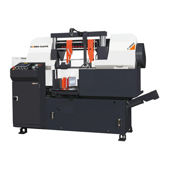
Page 23: Machine Parts Identification
Page 23 Instruction Manual for C-320NC (B090) 08/11/2018 MACHINE PARTS IDENTIFICATION Double Column Idle Wheel Cross Link Drive Wheel Blade Tension Controller Blade Tension Meter Chip Conveyor (optional) Control Panel with dual control valve ... - Page 24 Page 24 Instruction Manual for C-320NC (B090) 08/11/2018 Control Panel Rear Vise Cylinder Rear Vise Assembly Length Setting Stopper Rear Vise Feed Cylinder Discharge Table Blade Motor Chip Conveyor (optional) Machine top view ...
-
Page 25: Floor Plan
Page 25 Instruction Manual for C-320NC (B090) 08/11/2018 FLOOR PLAN 653 607 1850.2 2101.48 Machine top view 2‐5... - Page 26 Page 26 Instruction Manual for C-320NC (B090) 08/11/2018 Machine side view 2‐6 ...
-
Page 27: Section 3 – Moving & Installation
Page 27 Instruction Manual for C-320NC (B090) 08/11/2018 Section 3 MOVING & INSTALLATION LOCATION & ENVIRONMENT UNPACKING & INSPECTING LIFTING REMOVING SHIPPING BRACKET CLEANING INSTALLING RELOCATING LOCATION & ENVIRONMENT For your safety, please read all information regarding installation before proceeding. Install your machine in a place satisfying all of the following conditions: Space: Leave enough free space around the machine for loading work and unloading cut‐off pieces as well as for maintenance and inspection. Refer to Section 2 General Information ‐ Specification for machine dimensions and floor space. Environment: Well lighted (500 lumen at minimum). Floor kept dry at all times in order to prevent operators from slipping. Away from direct exposure to the sunlight Room temperature between 5˚C to 40˚C. ... -
Page 28: Unpacking & Inspecting
Page 28 Instruction Manual for C-320NC (B090) 08/11/2018 UNPACKING & INSPECTING Unpack your machine carefully to avoid damage to machine parts or surfaces. Upon arrival of your new band saw, please confirm that your machine is the correct model and it comes in the same specification you ordered by checking the model plate on the machine base. It is also imperative that a thorough inspection be undertaken to check for any damage that could have occurred during shipping. Pay special attention to machine surface, equipments furnished and the electrical and hydraulic systems for damaged cords, hoses and fluid leaks. In the event of damage caused during shipping, please contact your dealer and consult about filing a damage claim with the carrier. Your machine comes in with a set of tools for you to maintain the machine. The accessories furnished are as follows: 1. Tool box 1 pc 2. Grease gun 1 pc 3. Screwdriver (+, ‐) 2 pcs 4. Open‐ended spanner 3 pcs 5. Hexagon wrench 1 set 6. ... -
Page 29: Lifting
Page 29 Instruction Manual for C-320NC (B090) 08/11/2018 LIFTING When moving the machine, we strongly suggest you choose any one of the methods described below to move your machine. 1. Use a crane Move the machine to its location by using a crane and a wire rope sling that can fully withstand the weight of the machine (refer to machine specification under Section 2 General Information). Machine lifting is likely to damage the machine if not performed properly. You must have a qualified crane operator to perform the job. You must use tools and equipment with the proper tensile strength and use proper method when moving your machine. Apply the wire rope sling to the lifting hooks on the four ends of the machine. Refer to Illustration: Lifting Points for exact locations. Slowly lift the machine. Be sure to protect the machine from impact or shock during this procedure. Also watch out your own fingers and feet to avoid injuries. - Page 30 Page 30 Instruction Manual for C-320NC (B090) 08/11/2018 2. Use a forklift Most users choose this method to move their machine because it is easy to set up. Make sure that the lifting rod can fully withstand the weight of the machine. (Refer to Section 2 – General Information for Specifications) Machine lifting is likely to damage the machine if not performed properly. You must have a qualified forklift operator to perform the job. You must apply proper forklift technique to avoid damage to the machine. Make sure the forks are able to reach in at least 2/3 of the machine depth. You must keep the machine balanced at all times. Make sure the forks are centered before use. ...
-
Page 31: Illustration: Lifting Points
Page 31 Instruction Manual for C-320NC (B090) 08/11/2018 Illustration: Lifting Points 3‐5... -
Page 32: Removing Shipping Bracket
Page 32 Instruction Manual for C-320NC (B090) 08/11/2018 REMOVING SHIPPING BRACKET After the machine has been properly positioned, remove the shipping bracket that is used to lock the saw frame and the saw bed. Retain this bracket so that it can be used again in the event that your machine must be relocated. CLEANING After the machine has been placed at the designated position, remove the rust‐preventive grease with wiping cloth dampened with cleaning oil or kerosene. Apply machine oil to machine surfaces that are prone to rust. Do not remove the rust‐preventive grease with a metal scraper and do not wipe the painted surfaces with solvent as doing so would damage surface paint. INSTALLING Cosen’s bandsaw machine is relatively easy to install. Follow these six easy steps to install your machine. Connect ... -
Page 33: Supplying Hydraulic Oil
Page 33 Instruction Manual for C-320NC (B090) 08/11/2018 Supplying hydraulic oil Open the filler cap and fill the hydraulic oil tank to above 2/3 or full level. Check the sight gauge to make sure the oil level in the tank. Refer to specification chart under Section 2 for tank capacity. Supplying coolant Fill the coolant tank to the middle level of the sight gauge by pouring the coolant from above the chip conveyor. Use the sight gauge to check the coolant level remaining in the tank. Always check the coolant supply before starting the machine. If the coolant pump is started without enough coolant supply in the tank, the pump and its drive motor may be damaged. Refer to specification chart under Section 2 General Information for tank capacity. ... -
Page 34: Connecting Electric Power
Page 34 Instruction Manual for C-320NC (B090) 08/11/2018 Connecting electric power Have a qualified electrician make the electrical connections. If the power supply voltage is different from the transformer and motor connection voltage shown on the label attached to the electrical compartment of the machine, contact COSEN or your agent immediately. Connect to power supply independently and directly. Avoid using the same power supply with electric spark machines such as electric welder. Unstable electric tension may affect your machine’s electric installation from working properly. Ground the machine with an independent grounding conductor. Supply voltage: 90 ‐ 110 of nominal supply voltage. Source frequency: 99 ‐ 101 of nominal frequency. Refer to the specification chart under Section 2 for total electric power consumption of the motors and make sure your shop circuit breaker is capable of this consumption amount. Also use a power supply cable of proper size to suit the power supply voltage. Turn off the shop circuit breaker. Make sure the machine circuit breaker switch on the electrical compartment door is turned to OFF. Remove the screw securing the electrical compartment and then open the door. Pull the power supply cable and grounding conductor through the power supply inlet into the electrical compartment. (Shown right) Connect the power supply cable to the circuit breaker (N.F.B.) to the R, S and T terminals, and connect the ground cable to the E terminal. Close the compartment door and fasten the screw ... -
Page 35: Installing Roller Table (Optional)
Page 35 Instruction Manual for C-320NC (B090) 08/11/2018 Leveling Place spirit level on the vise slide plates and the work feed table. Level the machine in both directions i.e. along and across the machine. Adjust the level of the machine by turning the leveling bolts. Make sure all leveling bolts evenly support the machine weight. Anchoring the machine Normally there is no need to anchor the machine. If the machine is likely to vibrate, fix the machine to the floor with anchor bolts. Shock absorption steel plates are provided and can be placed under each leveling bolt to prevent their sinking into the concrete floor. Installing roller table (optional) The roller table is used to support long material at the rear and/or the front of the machine. If you have ordered the optional roller table for cutting long material, position it before or behind ... -
Page 36: Relocating
Page 36 Instruction Manual for C-320NC (B090) 08/11/2018 RELOCATING We recommend you follow these procedures when relocating or shipping your machine to other place: 1. Descend the saw frame to its lowest position then turn off the power. 2. Fix the saw frame using the shipping bracket that originally came with the machine. 3. If you are shipping the machine, pack the machine carefully with industrial plastic wraps to protect it from dust. 4. Use a crane or forklift to raise it. If a crane is used to lift the machine, ensure that the lifting cable is properly attached to the machine. 5. Do not forget to include the equipments originally furnished including the shock absorption steel plates and the instruction manual. 3‐10... -
Page 37: Section 4 – Operating Instructions
Page 37 Instruction Manual for C-320NC (B090) 08/11/2018 Section 4 OPERATING INSTRUCTION SAFETY PRECAUTIONS BEFORE OPERATING CONTROL PANEL STANDARD ACCESSORIES OPTIONAL ACCESSORIES UNROLLING & INSTALLING THE BLADE ADJUSTING WIRE BRUSH ADJUSTING SAW ARM ADJUSTING BLADE SPEED PLACING WORKPIECE ONTO WORKBED... -
Page 38: Safety Precautions
Page 38 Instruction Manual for C-320NC (B090) 08/11/2018 SAFETY PRECAUTIONS For your safety, please read and understand the instruction manual before you operate the machine. The operator should always follow these safety guidelines: The machine should only be used for its designated purpose. -
Page 39: Before Operating
Page 39 Instruction Manual for C-320NC (B090) 08/11/2018 BEFORE OPERATING Choosing an appropriate saw blade and using the right cutting method is essential to your cutting efficiency and safety. Select a suitable saw blade and cutting method based on your work material and job requirements e.g. -
Page 40: Control Panel
Page 40 Instruction Manual for C-320NC (B090) 08/11/2018 CONTROL PANEL The control panel is located on the top of the electrical box. It includes the following function: power system, hydraulic system, cooling system and the human-machine–interface (HMI). The operator must fully understand the function of each switch and button before operating the machine. -
Page 41: Control Buttons
Page 41 Instruction Manual for C-320NC (B090) 08/11/2018 Control Buttons 1. Emergency stop button Press this button to stop the machine in an emergency. When the button is pressed, it brings the machine to a full stop. The button locks when pressed. In order to unlock it, please turn the button clockwise. - Page 42 Page 42 Instruction Manual for C-320NC (B090) 08/11/2018 9. Feed forward button When this button is pressed, the feeding workbed will move forward. Press and hold the button to feed forward. As soon as the button is released, the feeding workbed will stop moving forward.
-
Page 43: Blade Descend Pressure & Speed
Page 43 Instruction Manual for C-320NC (B090) 08/11/2018 Blade Descend Pressure and Speed The part of control panel is where cutting pressure and saw bow descend speed can be adjusted. 1. Cutting pressure control knob This pressure control knob is used to adjust the cutting pressure of the blade. - Page 44 RS422 MMI port Environment No condensation and rust Startup Screen After the power is turned on, Cosen’s logo will appear as the startup screen, followed by the main operation menu.. Main control menu The main control menu includes some operating button that were used on the control panel of the earlier machines.
- Page 45 Page 45 Instruction Manual for C-320NC (B090) 08/11/2018 Refer to the table below for descriptions of each function. Item Function Description Hydraulic start When the power is turned on, press this button to start the hydraulic motor. A solid yellow icon indicates the hydraulic system has been turned on.
- Page 46 Page 46 Instruction Manual for C-320NC (B090) 08/11/2018 Item Function Description in action under AUTO mode, the machine will stop after the individual cut is finished. Switching to manual mode at any time other than cutting, the machine will proceed with the next cut until it is finished.
- Page 47 Page 47 Instruction Manual for C-320NC (B090) 08/11/2018 Item Function Description System parameter Press this button to set up system parameters. Password is required. setting All parameters have been set up by the manufacturer. In order to prevent random change from being made to these parameters and affect cutting precision and machine life, this function is protected with a set of password.
- Page 48 Page 48 Instruction Manual for C-320NC (B090) 08/11/2018 Item Function Description Front vise status Indicates if the front vises have clamped and secured the workpiece. indicator When the front vises have secured the workpiece, the clamping vise icon on the right will turn solid white.
- Page 49 Page 49 Instruction Manual for C-320NC (B090) 08/11/2018 Cutting status display & setup When cutting is in operation, press to enter cutting status display and setup page. Page 1 – cutting status display This page shows the following information (from top to bottom): ...
- Page 50 Page 50 Instruction Manual for C-320NC (B090) 08/11/2018 Press Home to return to the main control menu. Press PGUP to go back to the previous setup page. Press Next to go to the next setup page. For machines with optional blade deviation detector installed, additional two command are provided: ...
- Page 51 Page 51 Instruction Manual for C-320NC (B090) 08/11/2018 Cutting program setup When cutting is in operation, press to quickly access the cutting program setup page (the same as page 3 of the cutting status display and setup page) This setup page is the same as page 3 of the cutting status display and setup page.
- Page 52 Page 52 Instruction Manual for C-320NC (B090) 08/11/2018 PLC Monitor Shows all signals of the PLC system. Press Home to return to the main control menu. Error report Page 1 – error report Lists a historical report of the errors and the time of occurrence.
- Page 53 Page 53 Instruction Manual for C-320NC (B090) 08/11/2018 Error Error Description Solution Code M300 Front vises not clamping Check if the queen valve works M301 Rear vises not clamping Check if the queen valve works M303 Lower limit switch error...
-
Page 54: Standard Accessories
Page 54 Instruction Manual for C-320NC (B090) 08/11/2018 STANDARD ACCESSORIES Blade tension device This blade tension device equipped with hydraulic cylinder provides appropriate tension to the saw blade. To tighten the saw blade, turn the selector to Upon saw blade breakage, the safety device will activate and automatically stop all machine operation. - Page 55 Page 55 Instruction Manual for C-320NC (B090) 08/11/2018 Quick approach device This device allows the blade to quickly descend to just right above the material to save you operation time. Split front vises The spilt vises are a clever design to make sure your workpiece is tightly clamped by the two vises from both sides of the blade, maximizing stability and cutting precision.
-
Page 56: Optional Accessories
Page 56 Instruction Manual for C-320NC (B090) 08/11/2018 Coolant pump When the hydraulic system is turned on, the coolant pump can be operated individually from the control panel. Coolant can be used to wash off chips as well as providing cooling during cutting. - Page 57 Page 57 Instruction Manual for C-320NC (B090) 08/11/2018 Hydraulic top clamps The top clamp device composed of two clamps is installed on top of the front and rear vises before executing bundle cutting. Refer to Using Top Clamp for Bundle Cutting for operating procedure on bundle cutting.
- Page 58 Page 58 Instruction Manual for C-320NC (B090) 08/11/2018 How to Adjust 1. Loosen the nuts. 2. Adjust the proximity sensor until the blade deviation value shown the display returns to zero. (Please refer to the next page.) 3. Tighten the nuts.
-
Page 59: Unrolling & Installing The Blade
Page 59 Instruction Manual for C-320NC (B090) 08/11/2018 Picture C: Deviation Value Set-Up & On/Off button Deviation Value Set-Up: Deviation Value Set- Set up the tolerance of deviation value; if the value out of range when blading for 15 seconds, the machine... - Page 60 Page 60 Instruction Manual for C-320NC (B090) 08/11/2018 Unroll and roll the blade Installing a new blade Step 1 - Select the most suitable saw blade for your workpiece considering the size, shape and material. Step 2 - Turn on the machine power by switching to ON and turn on the hydraulic system.
- Page 61 Page 61 Instruction Manual for C-320NC (B090) 08/11/2018 Step 6 - Open the idle and drive wheel covers. Step 7 - Press the Blade Clip device to hold onto the blade. This device makes blade changing easy and feasible even with only one operator available.
-
Page 62: Adjusting Wire Brush
Page 62 Instruction Manual for C-320NC (B090) 08/11/2018 covers and make sure the blade has not fallen off the drive and idle wheels. If the blade has shifted, follow the same procedure to reinstall the blade again. Step 19 - Adjust wire brush to a proper position. Refer to Adjusting Wire Brush in this section. -
Page 63: Adjusting Blade Speed
Page 63 Instruction Manual for C-320NC (B090) 08/11/2018 Locking Lever Inserts Lock Nut ADJUSTING BLADE SPEED Step 1 – Set the flow control to “0” position. Step 2 – Press the saw blade start button to start the blade. Step 3 – Turn the blade speed control knob to adjust the blade speed. The blade speed should be adjusted based on the size and the material of the workpiece. -
Page 64: Positioning Workpiece For Cutting
Page 64 Instruction Manual for C-320NC (B090) 08/11/2018 POSITIONING WORKPIECE FOR CUTTING Follow these steps to position your workpiece: Step Action Press the rear vise clamp button until the workpiece is rear vises clamp material securely clamped. Move the vertical alignment rollers toward workpiece align vertical rollers until it stands against the workpiece. -
Page 65: Adjusting Coolant Flow
Page 65 Instruction Manual for C-320NC (B090) 08/11/2018 ADJUSTING COOLANT FLOW Step 1 – Press the saw blade start button to start the saw blade drive motor. Step 2 – Press the saw bow down button to lower the saw bow. -
Page 66: Test -Running The Machine
Page 66 Instruction Manual for C-320NC (B090) 08/11/2018 TEST-RUNNING THE MACHINE Test-running this machine can ensure good machine performance in the future. We suggest you run the following tests on the machine before first use: Testing machine performance: Turn on the power and run a basic performance test after you finish installing the machine. Follow these steps to test machine performance: Step 1 –... - Page 67 Page 67 Instruction Manual for C-320NC (B090) 08/11/2018 Step 6 – Adjust blade descend speed control knob to obtain a suitable blade descend speed for your material. Step 7 – Start running the blade. Before you start cutting, check again that there is no other object in the cutting area.
-
Page 68: Using Top Clamp For Bundle Cutting
Page 68 Instruction Manual for C-320NC (B090) 08/11/2018 USING TOP CLAMP FOR BUNDLE CUTTING Before Cutting , Make sure that the bundle is properly tightly clamped but not being distorted by clamp force. Any improper bundle cutting can cause damage to the blade, reduce the blade life. -
Page 69: Terminating A Cutting Operation
Page 69 Instruction Manual for C-320NC (B090) 08/11/2018 Proper and improper stacking of workpieces Proper Improper Step 4 – Align the top clamp cylinders with the center of the workpiece and tighten the lock nuts. Step 5 – Turn the top clamp handles so that the clearance between the top clamp jaw and the top of the bundled workpiece is within 5 to 10 mm ( 0.2 ~ 0.4 inch). - Page 70 Page 70 Instruction Manual for C-320NC (B090) 08/11/2018 4-34...
- Page 71 Page 71 Instruction Manual for C-320NC (B090) 08/11/2018 Section 5 ELECTRICAL SYSTEM ELECTRICAL CIRCUIT DIAGRAMS Non‐CE model: page 5‐2~5‐5 CE model: page 5‐6~5‐9 5‐1...
- Page 72 Page 72 Instruction Manual for C-320NC (B090) 08/11/2018...
- Page 73 Page 73 Instruction Manual for C-320NC (B090) 08/11/2018...
- Page 74 Page 74 Instruction Manual for C-320NC (B090) 08/11/2018...
- Page 75 Page 75 Instruction Manual for C-320NC (B090) 08/11/2018...
- Page 76 Page 76 Instruction Manual for C-320NC (B090) 08/11/2018 張 1030219 鴻 昌...
- Page 77 Page 77 Instruction Manual for C-320NC (B090) 08/11/2018 1030219 張 鴻 昌...
- Page 78 Page 78 Instruction Manual for C-320NC (B090) 08/11/2018 1030219 張 鴻 昌...
- Page 79 Page 79 Instruction Manual for C-320NC (B090) 08/11/2018 張 1030219 鴻 昌...
- Page 80 Page 80 Instruction Manual for C-320NC (B090) 08/11/2018 ...
- Page 81 Page 81 Instruction Manual for C-320NC (B090) 08/11/2018 Section 6 HYDRAULIC SYSTEM HYDRAULIC DIAGRAMS CE model: page 6‐2~6‐6 6‐1...
- Page 82 Page 82 Instruction Manual for C-320NC (B090) 08/11/2018...
- Page 83 Page 83 Instruction Manual for C-320NC (B090) 08/11/2018...
- Page 84 Page 84 Instruction Manual for C-320NC (B090) 08/11/2018...
- Page 85 Page 85 Instruction Manual for C-320NC (B090) 08/11/2018 Norm Item Part No. Part Name PP-43503 Solenoid valve DFB-2B2-02-C1 PP-43121-03 Guiding check valve 3/8 3000PSI 4:1 PP-43521 Solenoid valve DFB-3C4-O2-C1 PP-43125 Guiding check valve MPC-02-W AGC-10200-1 Saw bow cylinder assembly AGB-707270...
- Page 86 Page 86 Instruction Manual for C-320NC (B090) 08/11/2018 Item Part No. Part Name PHD-02D-1000 Hydraulic hose PHD-02D-1100 Hydraulic hose PHD-02D-1300 Hydraulic hose PHD-02D-1900 Hydraulic hose PHD-02D-200 Hydraulic hose PHD-02D-220 Hydraulic hose PHD-02D-2200 Hydraulic hose PHD-02D-260 Hydraulic hose PHD-02D-280 Hydraulic hose...
-
Page 87: Section 7 – Bandsaw Cutting: A Practical Guide
Page 87 Instruction Manual for C-320NC (B090) 08/11/2018 Section 7 BANDSAW CUTTING: A PRACTICAL GUIDE INTRODUCTION SAW BLADE SELECTION VISE LOADING BLADE BREAK-IN... -
Page 88: Introduction
Page 88 Instruction Manual for C-320NC (B090) 08/11/2018 INTRODUCTION TPI: The number of teeth per inch as measured from gullet to gullet. 2. Tooth Rake Angle: The angle of the tooth face measured with respect to a line perpendicular to the cutting direction of the saw. -
Page 89: Vise Loading
Page 89 Instruction Manual for C-320NC (B090) 08/11/2018 4. Tooth pitch The main factor here is the contact length of the blade in the workpiece. If it is 4P, 25.4 ÷ 4 P = 6.35 mm, that is, one tooth is 6.35 mm. -
Page 90: Bladebreak -In
Page 90 Instruction Manual for C-320NC (B090) 08/11/2018 The following diagrams suggest some costeffective ways of loading and fixturing. Be sure, regardless of the arrangement selected, that the work can be firmly secured to avoid damage to the machine or injury to the operator. -
Page 91: Section 8 – Maintenance & Service
Page 91 Instruction Manual for C-320NC (B090) 08/11/2018 Section 8 MAINTENANCE & SERVICE INTRODUCTION BASIC MAINTENANCE MAINTENANCE SCHEDULE BEFORE BEGINNING A DAY’S WORK AFTER ENDING A DAY’S WORK Every 2 weeks First 600hrs for new machine,then every 1200hrs for routine change... -
Page 92: Maintenance Schedule
Page 92 Instruction Manual for C-320NC (B090) 08/11/2018 MAINTENANCE SCHEDULE We suggest you do the maintenance on schedule. Before beginning a day’s work 1. Please check the hydraulic oil level. If oil level volume is below 1/2, please add oil as necessary.(Filling up to 2/3 level is better for system operation.) - Page 93 Page 93 Instruction Manual for C-320NC (B090) 08/11/2018 Grease Injection Hole: Grease Injection Nozzles at the middle of drive wheel Grease Injection Nozzle and idle wheel; (You need to rotate the wheel until you ssee the Grease injection nozzle.) : The position of injection indicating.
-
Page 94: First 600Hrs For New Machine,Then Every 1200Hrs
Page 94 Instruction Manual for C-320NC (B090) 08/11/2018 First 600hrs for new machine,then every 1200hrs for routine change Replace the transmission oil after operating for first 600hrs for new machine,then every 1200hrs Recommended gear oil Shell Omala oil HD220 ... -
Page 95: Every Six Months
Page 95 Instruction Manual for C-320NC (B090) 08/11/2018 Every six months 1.Clean the filter of the cutting fluid. 2.Replace the transmission oil for every half of a year(or 1200 hours). Check the sight gauge to ascertain the transmission level. Recommended TRANSMISSION OIL ... -
Page 96: Oil Recommendation For Maintenance
Page 96 Instruction Manual for C-320NC (B090) 08/11/2018 OIL RECOMMENDATION FOR MAINTENANCE Item Method Revolution Suggest oil Dovetail guide Keep grease covered. Antirust. Daily Shell R2 Roller bearing Sweep clean and oil with lubricant. Daily SEA #10 Bed roller / surface Sweep clean and oil with lubricant. -
Page 97: Section 9 – Troubleshooting
Page 97 Instruction Manual for C-320NC (B090) 08/11/2018 Section 9 TROUBLESHOOTING INTRODUCTION PRECAUTIONS GENERAL TROUBLES & SOLUTIONS MINOR TROUBLES & SOLUTIONS MOTOR TROUBLES & SOLUTIONS BLADE TROUBLES & SOLUTIONS SAWING PROBLEMS & SOLUTIONS RE-ADJUSTING THE ROLLER TABLE INTRODUCTION All the machines manufactured by us pass a 48 hours continuously running test before shipping out and we are responsible for the after sales service problems during the warranty period if the machines are used normally. -
Page 98: Precautions
Page 98 Instruction Manual for C-320NC (B090) 08/11/2018 PRECAUTIONS When an abnormality occurs in the machine during operation, you can do it yourself safely. If you have to stop machine motion immediately for parts exchanging, you should do so according to the following procedures: ... -
Page 99: Minor Troubles & Solutions
Page 99 Instruction Manual for C-320NC (B090) 08/11/2018 MINOR TROUBLES & SOLUTIONS TROUBLE PROBABLE CAUSE SUGGESTED REMEDY Saw blade motor does not run Overload relay activated Reset even though blade drive button Saw blade is not at forward Press SAW FRAME is pressed. -
Page 100: Blade Troubles & Solutions
Page 100 Instruction Manual for C-320NC (B090) 08/11/2018 BLADE TROUBLES AND SOLUTIONS DISCONNECT POWER CORD TO MOTOR BEFORE ATTEMPTING ANY REPAIR OR INSPECTION. TROUBLE PROBABLE CAUSE SUGGESTED REMEDY Too few teeth per inch Use finer tooth blade Loading of gullets Use coarse tooth blade or cutting lubricant. -
Page 101: Sawing Problems & Solutions
Page 101 Instruction Manual for C-320NC (B090) 08/11/2018 SAWING PROBLEMS AND SOLUTIONS Other than this manual, the manufacturer also provides some related technical documents listed as follows: Sawing Problems and Solutions Vibration during cutting Failure to cut Short life of saw blade... - Page 102 Page 102 Instruction Manual for C-320NC (B090) 08/11/2018 SOLUTIONS TO SAWING PROBLEMS Table Of Contents #1. Heavy Even Wear On Tips and Corners Of Teeth #11. Uneven Wear Or Scoring On The Sides Of Band #2. Wear On Both Sides Of Teeth #12.
- Page 103 Page 103 Instruction Manual for C-320NC (B090) 08/11/2018 #2. Wear On Both Sides Of Teeth Probable Cause : A. Broken, worn or missing back-up guides allowing teeth to contact side guides. B. Improper side guides for band width. C. Backing the band out of an incomplete cut.
- Page 104 Page 104 Instruction Manual for C-320NC (B090) 08/11/2018 #5. Body Breakage Or Cracks From Back Edge Probable Cause : A. Excessive back-up guide "preload" will cause back edge to work harden which results in cracking. B. Excessive feed rate. C. Improper band tracking – back edge rubbing heavy on wheel flange.
- Page 105 Page 105 Instruction Manual for C-320NC (B090) 08/11/2018 #8. Gullets Loading Up With Material Probable Cause : A. Too fine of a tooth pitch – insufficient gullet capacity. B. Excessive feeding rate producing too large of a chip. C. Worn, missing or improperly positioned chip brush.
- Page 106 Page 106 Instruction Manual for C-320NC (B090) 08/11/2018 #12. Heavy Wear And/Or Swagging On Back Edge Probable Cause : A. Excessive feed rate. B. Excessive back-up guide "preload". C. Improper band tracking – back edge rubbing heavy on wheel flange.
- Page 107 Page 107 Instruction Manual for C-320NC (B090) 08/11/2018 #16. Body Breakage Or Cracks From Gullets Probable Cause : A. Excessive back-up guide "preload". B. Improper band tension. C. Guide arms spread to maximum capacity. D. Improper beam bar alignment. E. Side guide adjustment is too tight.
-
Page 108: Re-Adjusting The Roller Table
Page 108 Instruction Manual for C-320NC (B090) 08/11/2018 #20. Broken Band Shows A Twist In Band Length Probable Cause : A. Excessive band tension B. Any of the band conditions which cause the band to be long (#18) or short (#19) on tooth edge. -
Page 109: Section 10 – Parts
Page 109 Instruction Manual for C-320NC (B090) 08/11/2018 Section 10 PARTS SPARE PARTS RECOMMENDATIONS PART LIST SPARE PARTS RECOMMENDATIONS The following table lists the common spare parts we suggest you purchase in advance: Part Name Part Name Saw blade Coolant tank filter... - Page 110 Page 110 Instruction Manual for C-320NC (B090) 08/11/2018...
- Page 111 Page 111 Instruction Manual for C-320NC (B090) 08/11/2018 Water gauge water gauge sight (含刻度表) 3" PP-21030 oil level gauge...
- Page 112 Page 112 Instruction Manual for C-320NC (B090) 08/11/2018 10-4...
- Page 113 Page 113 Instruction Manual for C-320NC (B090) 08/11/2018 10-5...
- Page 114 Page 114 Instruction Manual for C-320NC (B090) 08/11/2018 10-6...
- Page 115 Page 115 Instruction Manual for C-320NC (B090) 08/11/2018 PDA-8-20 PBA-16-60 PQA-16 PRB-10-50 Rear fixed vise AGC-2202T 後固定虎鉗 AGC-2200-1 Rear fixed cylinder assy 後虎鉗固定油壓缸組 5 x 10 mm Oval head screw (+) 丸頭螺絲(十字)(公) PFA-5-10 AGC-2209 Vise cover 固定虎鉗蓋 x P 1.75 POA-12-175 螺母(公)
- Page 116 Page 116 Instruction Manual for C-320NC (B090) 08/11/2018 10-8...
- Page 117 Page 117 Instruction Manual for C-320NC (B090) 08/11/2018 10-9...
- Page 118 Page 118 Instruction Manual for C-320NC (B090) 08/11/2018 10-18 10-10...
- Page 119 Page 119 Instruction Manual for C-320NC (B090) 08/11/2018 10-19 10-11...
- Page 120 Page 120 Instruction Manual for C-320NC (B090) 08/11/2018 10-20 10-12...
- Page 121 Page 121 Instruction Manual for C-320NC (B090) 08/11/2018 10-23 10-13...
- Page 122 Page 122 Instruction Manual for C-320NC (B090) 08/11/2018 10-24 10-14...
- Page 123 Page 123 Instruction Manual for C-320NC (B090) 08/11/2018 10-15 10-27...
- Page 124 Page 124 Instruction Manual for C-320NC (B090) 08/11/2018 10-28 10-16...
- Page 125 Page 125 Instruction Manual for C-320NC (B090) 08/11/2018 10-29 10-17...
- Page 126 Page 126 Instruction Manual for C-320NC (B090) 08/11/2018 10-18 10-30...
-
Page 127: Part List
Page 127 Instruction Manual for C-320NC (B090) 08/11/2018 PART LIST PART P 2M ROLLER TABLE (OPTIONAL) PART N 05OPR-320-2M 10-31 10-19... - Page 128 Page 128 Instruction Manual for C-320NC (B090) 08/11/2018 PART LIST PART P 2M ROLLER TABLE (OPTIONAL) PART N 05OPR-320-2M ITEM PART NO. PART NAME PART NAME (CH) PART SPEC. COUNT UNIT OPR-5002A roller table (440W) PLA-12-20 bolt M12 x 20L...
- Page 129 Page 129 Instruction Manual for C-320NC (B090) 08/11/2018 10-33 10-21...
- Page 130 Page 130 Instruction Manual for C-320NC (B090) 08/11/2018 10-34 10-22...
- Page 131 Page 131 Instruction Manual for C-320NC (B090) 08/11/2018 10-35 10-23...
- Page 132 Page 132 Instruction Manual for C-320NC (B090) 08/11/2018 10-24...
- Page 133 Page 133 Instruction Manual for C-320NC (B090) 08/11/2018 10-25...
- Page 134 Page 134 Instruction Manual for C-320NC (B090) 08/11/2018 10-26...
- Page 135 Page 135 Instruction Manual for C-320NC (B090) 08/11/2018 10-27...
- Page 136 Page 136 Instruction Manual for C-320NC (B090) 08/11/2018...
- Page 137 Page 137 Instruction Manual for C-320NC (B090) 08/11/2018 10-28...
- Page 138 Page 138 Instruction Manual for C-320NC (B090) 08/11/2018 10-29...
- Page 139 Page 139 Instruction Manual for C-320NC (B090) 08/11/2018 10-30...
- Page 140 Page 140 Instruction Manual for C-320NC (B090) 08/11/2018 10-31...
- Page 141 Page 141 Instruction Manual for C-320NC (B090) 08/11/2018 10-32...
- Page 142 Page 142 Instruction Manual for C-320NC (B090) 08/11/2018 10-33...
- Page 143 Page 143 Instruction Manual for C-320NC (B090) 08/11/2018 10-34...
- Page 144 Page 144 Instruction Manual for C-320NC (B090) 08/11/2018 10-35...
- Page 145 Page 145 Instruction Manual for C-320NC (B090) 08/11/2018 10-36...
- Page 146 Page 146 Instruction Manual for C-320NC (B090) 08/11/2018 10-37...
- Page 147 Page 147 Instruction Manual for C-320NC (B090) 08/11/2018 10-38...
- Page 148 Page 148 Instruction Manual for C-320NC (B090) 08/11/2018 10-39...
- Page 149 Page 149 Instruction Manual for C-320NC (B090) 08/11/2018 10-40...
- Page 150 Page 150 Instruction Manual for C-320NC (B090) 08/11/2018 10-41...
- Page 151 Page 151 Instruction Manual for C-320NC (B090) 08/11/2018 10-42...
- Page 152 Page 152 Instruction Manual for C-320NC (B090) 08/11/2018 10-43...
- Page 153 Page 153 Instruction Manual for C-320NC (B090) 08/11/2018 10-44...
- Page 154 Page 154 Instruction Manual for C-320NC (B090) 08/11/2018 10-45...
- Page 155 Page 155 Instruction Manual for C-320NC (B090) 08/11/2018 10-46...
- Page 156 Page 156 Instruction Manual for C-320NC (B090) 08/11/2018 10-47...
- Page 157 Page 157 Instruction Manual for C-320NC (B090) 08/11/2018 10-48...
- Page 158 Page 158 Instruction Manual for C-320NC (B090) 08/11/2018 10-49...
- Page 159 Page 159 Instruction Manual for C-320NC (B090) 08/11/2018 10-50...
- Page 160 Page 160 Instruction Manual for C-320NC (B090) 08/11/2018 10-51...
- Page 161 Page 161 Instruction Manual for C-320NC (B090) 08/11/2018 10-52...
- Page 162 Page 162 Instruction Manual for C-320NC (B090) 08/11/2018 10-53...
- Page 163 Page 163 Instruction Manual for C-320NC (B090) 08/11/2018 10-54...
- Page 164 Page 164 Instruction Manual for C-320NC (B090) 08/11/2018...
- Page 165 Page 165 Instruction Manual for C-320NC (B090) 08/11/2018 ...
- Page 166 Page 166 Instruction Manual for C-320NC (B090) 08/11/2018 COSEN SAWS Vertical Plate Saws Horizontal Billet Saws NC/CNC Band Saws Structural Miter‐Cutting Saws Automatic Band Saws Industry 4.0 Cosen Predictive Computing Visit our website at www.cosen.com COSEN MECHATRONICS CO., LTD. ...
Need help?
Do you have a question about the C-320NC and is the answer not in the manual?
Questions and answers
need blades for c-320nc ser: c1001846 need part numbers
need wear guides (saw blade) for the c-320nc ser:c1001846