
Related Manuals for Cosen AH-250H


Summary of Contents for Cosen AH-250H
-
Page 1: Instruction Manual
Page 1 Instruction Manual for AH-250H (B040) 04/12/2014 INSTRUCTION MANUAL AH-250H Automatic Hitch Feed Metal Cutting Band Saw (415V) 280 x 250mm (W x H) Rectangle B040... - Page 2 AH-250H. TECHNICAL ADVICE/ SPARE PARTS Please contact the COSEN-representative in your local area in case you need any technical advice or if you want to order spare parts. Instruction Manual: AH-250H Automatic Horizontal Bandsaw Ver.
- Page 3 However, if there are questions, please contact our agent or our factory for the nearest service or sales representative. Enough, already. I hope you find COSEN as incredibly smart as I do. If you have any suggestions for improvement, please tell us, we will appreciate your help.
-
Page 4: Table Of Contents
Page 4 Instruction Manual for AH-250H (B040) 04/12/2014 TABLE OF CONTENTS SECTION PAGE 1-1~5 SAFETY RULES GENERAL INFORMATIONS INTRODUCTION EQUIPMENT DESCRIPTION 2.2.1 SPECIFICATION 2.2.2 Identification of Main Parts & Terminology 2.2.3 Emergency Stop Button 2.2.4 Noise Level 2.2.5 Safety Devices and Guards 2-5~6 2.2.6... - Page 5 Page 5 Instruction Manual for AH-250H (B040) 04/12/2014 OPERATION INSTRUCTION SAFETY PRECAUTIONS PREPARATION FOR USE CONTROLS DESCRIPTION AND OPERATION 4.3.1 Control panel 4.3.2 Manual model TEST RUN THE MACHINE 4-15 HOW TO REPLACE THE SAW BLADE 4-16 HOW TO LOAD THE WORKPIECE...
- Page 6 Page 6 Instruction Manual for AH-250H (B040) 04/12/2014 SAWING PROBLEMS AND SOLUTIONS MINOR TROUBLE SHOOTING THE ADJUSTMENT OF THE FEEDING TABLE PART LIST INTRODUCTION 10-1 10.01 BAND SAW FOUNDATION ASS'Y 10-2~3 10.02 VISE MACHINE BODY ASS'Y 10-4~5 10.03 TRANSMISSION MACHINCAL ASS'Y 10-6~7 10.04 POWER UNIT ASS'Y...
-
Page 7: Safety Rules 1-1~5
Page 7 Instruction Manual for AH-250H (B040) 04/12/2014 Section 1 SAFETY RULES... - Page 8 Page 8 Instruction Manual for AH-250H (B040) 04/12/2014 SAFETY RULES Section 1 SECTION 1 SAFELY RULES Never wear gloves loose clothing when operating the machine. They may cause danger if they are caught in a running machine. Be sure to confirm that the area around the machine is cleared of people and obstacles every time...
- Page 9 Page 9 Instruction Manual for AH-250H (B040) 04/12/2014 SAFETY RULES Section 1 Use a water-soluble cutting fluid on this machine. Oil-based cutting fluids may emit smoke or catch fire, depending on the condition of their use. Never try to adjust the wire brush on the saw blade or remove chips when the saw blade is running.
- Page 10 Page 10 Instruction Manual for AH-250H (B040) 04/12/2014 SAFETY RULES Section 1 Stop the saw blade before you clean the machine. It is dangerous if hands or clothing are caught by the running blade. Be sure to prohibit any use of fire in the shop, and install a fire extinguisher or other fire control device near the machine when cutting titanium, magnesium, or any other material that produces flammable chips.
- Page 11 Page 11 Instruction Manual for AH-250H (B040) 04/12/2014 SAFETY RULES Section 1 Take preventive measures when cutting thin or short pieces from the work to keep them from falling. It is dangerous if the cut piece falls. Never start the saw blade unless it has been confirmed that the work is firmly clamped. If the work is not securely clamped with the vise, pieces will be forced out of the vise during cutting.
- Page 12 Page 12 Instruction Manual for AH-250H (B040) 04/12/2014 SAFETY RULES Section 1 Never step or stand on the roller table. It is dangerous if your foot slips on the rollers and you fall. Turn off the shop circuit breaker switch before servicing the machine. Then post a sign to inform...
- Page 13 Page 13 Instruction Manual for AH-250H (B040) 04/12/2014 Section 2 GENERAL INFORMATION...
-
Page 14: General Informations
Page 14 Instruction Manual for AH-250H (B040) 04/12/2014 GENERAL INFORMATION Section 2 SECTION 2 GENERAL INFORMATION 2.1 INTRODUCTION This automatic band saw is a model more popular than any other model as witnessed in many countries worldwide. This machine was developed by a group of R&D engineers over a considerable period of time assuring you of the highest efficiency and performance. -
Page 15: Specification
Page 15 Instruction Manual for AH-250H (B040) 04/12/2014 GENERAL INFORMATION Section 2 2.2.1 Specifications Specification of The Machine Automatic Band Saw Machine (AH-250H) MODEL 250 mm (10") (W ×H) 250 × 250 mm (10" × 10") MAX. CAPACITY (W ×H) 280 ×250 mm (11" ×10 ") 27, 40, 54, 68, 80 m/min. -
Page 16: Identification Of Main Parts & Terminology
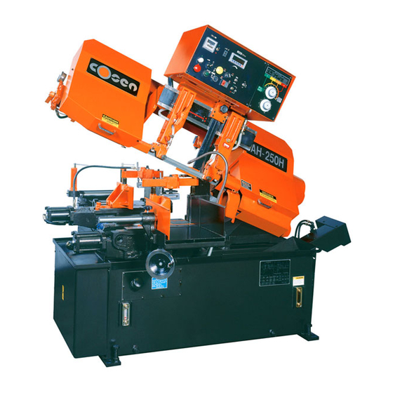
Page 16 Instruction Manual for AH-250H (B040) 04/12/2014 GENERAL INFORMATION Section 2 2.2.2 Identification of Main Parts & Terminology FIG 2-1 The main unit of the machine 2.2.3 Emergency Stop Button Your machine‘s emergency stop button is designed to be very easy to access. When you press it, it will stop the machine completely to avoid severe injury when an accident occurs. -
Page 17: Safety Devices And Guards 2-5~6
Page 17 Instruction Manual for AH-250H (B040) 04/12/2014 GENERAL INFORMATION Section 2 Excessive exposure to high levels of noise may cause impairment to hearing, but the vulnerability to hearing loss varies between individuals and must be taken into account in specifying an allowable limit for noise exposure. - Page 18 Page 18 Instruction Manual for AH-250H (B040) 04/12/2014 GENERAL INFORMATION Section 2 FIG 2-3 The machine of front view Safety moving element: All the major moving elements on the machine include: 1. Saw head assembly. 2. Saw wheels. 3. Saw blade guide/arm.
-
Page 19: Specification Of Electrical Equipment
Page 19 Instruction Manual for AH-250H (B040) 04/12/2014 GENERAL INFORMATION Section 2 users from being cut by the running saw blades. The vise clamp switch is to assure firm clamping of the workpiece. If the workpiece is not clamped properly, the saw blade is not allowed to run. -
Page 20: Guide To The Manual
Page 20 Instruction Manual for AH-250H (B040) 04/12/2014 GENERAL INFORMATION Section 2 AC110V 2. Waveform measurement circuit and measured waveform. 3. RC circuit Element marker have introduced in recent years spike killers (sometimes called arrester) which are made of mainly zinc oxide with a characteristic of varistor. Comparison of their characteristics toward surge voltage indicates that the former has a smooth attenuation curve with the crest value of a steep surge voltage being less than 4.5 times of the rated voltage. - Page 21 Page 21 Instruction Manual for AH-250H (B040) 04/12/2014 GENERAL INFORMATION Section 2...
- Page 22 Page 22 Instruction Manual for AH-250H (B040) 04/12/2014 Section 3 MOVING & INSTALLATION...
-
Page 23: Moving And Installation
Page 23 Instruction Manual for AH-250H (B040) 04/12/2014 MOVING AND INSTALLATION Section 3 SECTION 3 MOVING AND INSTALLATION 3.1 INTRODUCTION Your machine is made of three main system components: Machine equipment, hydraulic system, and electrical control system. Please read the entire manual carefully to obtain a thorough knowledge of the machine. - Page 24 Page 24 Instruction Manual for AH-250H (B040) 04/12/2014 MOVING AND INSTALLATION Section 3 • Apply the wire rope sling to the lifting hole at rear of the front vise slide and to the rear end of the machine. Please keep the machine balanced rear-front and left-right side when you are lifting up the machine.
-
Page 25: Installation Of The Machine
Page 25 Instruction Manual for AH-250H (B040) 04/12/2014 MOVING AND INSTALLATION Section 3 • You must apply proper forklift technique to avoid damage to the machine. • You also have to keep the machine balanced at all times. 3. Use rolling cylinders to place You can use this method in small buildings. -
Page 26: Safety Precautions
Page 26 Instruction Manual for AH-250H (B040) 04/12/2014 MOVING AND INSTALLATION Section 3 3.3.1 Safety Precautions Read the operating manual thoroughly to avoid improper operations. Environment: Avoid exposing machine to direct sunlight. ℃ ℃ Keep the room temperature between 5 to 40 Keep the humidity of your machine at 30%-95“(without condensation) to avoid dew on... - Page 27 Page 27 Instruction Manual for AH-250H (B040) 04/12/2014 MOVING AND INSTALLATION Section 3 MAIN SECTION MAIN SECTION Machine Body Hydraulic Unit Electrical Control Box Hydraulic Hose Work Tray Roller Table Cutting Length Preset Device Optional Roller Table Chip Conveyor Fig: 3.1 Floor Space Required with Optional Table...
- Page 28 Page 28 Instruction Manual for AH-250H (B040) 04/12/2014 MOVING AND INSTALLATION Section 3 MAIN SECTION MAIN SECTION Machine Body Chip Conveyor Electrical Control Box Hydraulic Unit Work Tray Hydraulic Hose Cutting Length Preset Device Roller Table Fig: 3.2 Stander Floor Space Required...
-
Page 29: Unpacking
Page 29 Instruction Manual for AH-250H (B040) 04/12/2014 MOVING AND INSTALLATION Section 3 3.3.4 Unpacking After the machine has been properly positioned, remove the shipping bracket. Unpack your machine carefully. Do not damage the machine surface paint. Remember to remove the bracket used to lock the saw frame and the saw bed. -
Page 30: Machine Leveling
Page 30 Instruction Manual for AH-250H (B040) 04/12/2014 MOVING AND INSTALLATION Section 3 1. For best performance, the band saw has to be placed on a solid and level foundation. The floor is recommended to have a carrying capacity of approximately 5 tons (including both machine and material weight). -
Page 31: Electrical Connections (Power Requirement)
Page 31 Instruction Manual for AH-250H (B040) 04/12/2014 MOVING AND INSTALLATION Section 3 Fill the cutting fluid tank with the proper cutting fluid mixture. Recommend Shell Dromus BS or Shell Lubricool Yellow Cutting Fluid is used, the ratio of cutting fluid to water should be approximately 1:15~1:20. -
Page 32: Working Conditions
Page 32 Instruction Manual for AH-250H (B040) 04/12/2014 MOVING AND INSTALLATION Section 3 220 415 440 380 Installing Fire Control Device Install a fire extinguisher or other fire control device in the shop to provide safety. 3.4 WORKING CONDITIONS For safety in operating working, we recommend the following: A well lighted work site. -
Page 33: Operation Instruction
Page 33 Instruction Manual for AH-250H (B040) 04/12/2014 Section 4 OPERATION INSTRUCTION... -
Page 34: Safety Precautions
Page 34 Instruction Manual for AH-250H (B040) 04/12/2014 OPERATING INSTRUCTION Section 4 SECTION 4 OPERATING INSTRUCTIONS 4.1 SAFETY PRECAUTIONS For your safety, please read and understand the instruction manual before you try to operate your machine. The operator should always follow the guidelines: •... -
Page 35: Controls Description And Operation
Page 35 Instruction Manual for AH-250H (B040) 04/12/2014 OPERATING INSTRUCTION Section 4 Advantage Disadvantage Have high cooling effect Remove paint Not flammable Lose rust protection effect when deteriorated Economical Foam Does not require cleaning of cut Putrefy products (especially when soluble) - Page 36 Page 36 Instruction Manual for AH-250H (B040) 04/12/2014 OPERATING INSTRUCTION Section 4 13 COUNTER ON / OFF SWITCH . POWER”ON” BUTTON indicator lamp Depressed this button the hydraulic motor and chip conveyor will star and the white light will come...
- Page 37 Page 37 Instruction Manual for AH-250H (B040) 04/12/2014 OPERATING INSTRUCTION Section 4 .QUICK APPROACH button This button is used to allow the sawhead to approach the workpiece quickly when the saw blade is at a distance from the workpiece. While this button is depressed, the sawhead descends quickly;...
- Page 38 Page 38 Instruction Manual for AH-250H (B040) 04/12/2014 OPERATING INSTRUCTION Section 4 | “ON” mode The coolant pump operates and the coolant supply begins. “OFF”mode The coolant pump halts and the coolant supply stops. WORKLAMP switch “ON” mode The work lamp operates.
- Page 39 The blade speed is shown here and the blade speed can be adjusted by stepless cariable speed mechanism. NOTE:The B.S.D (blade speed display) all of data setting by COSEN Machinery Industrial Co., Ltd. Therefore operator must understand DO NOT CHANGE ANY PARAMETER DATA BY USER.
- Page 40 Page 40 Instruction Manual for AH-250H (B040) 04/12/2014 OPERATING INSTRUCTION Section 4 Ration setting 0.001 ~9.999 One turn signal 1 ~ 9999cps Sampling time 1 ~ 60sec Select function 0:standard mode. 1:unit changing mode Panel lock 0:Release. 1:Lock Table 4-2 Reference number function Parameter Setting Procedure Press 3”PREST”+9“ENT”...
- Page 41 Page 41 Instruction Manual for AH-250H (B040) 04/12/2014 OPERATING INSTRUCTION Section 4 Quick Approach Device This device is used to allow the saw blade to descend to position quickly, just above the position at which the saw blade reaches the workpiece.
- Page 42 Page 42 Instruction Manual for AH-250H (B040) 04/12/2014 OPERATING INSTRUCTION Section 4 Saw Blade Speed Control Panel 1. Cutting Pressure Control Dial 2. Saw Blade Down feed Rate Control Dial Fig 4-2: Cutting Parameters Control Panel Cutting Parameters Control Panel 1.
-
Page 43: Manual Model
Page 43 Instruction Manual for AH-250H (B040) 04/12/2014 OPERATING INSTRUCTION Section 4 2. Saw Blade Down feed Rate Control Dial This flow control dial is used to adjust the down feed speed of the blade according to the material to be cut, the cutting shape and the cutting cross section area. - Page 44 Page 44 Instruction Manual for AH-250H (B040) 04/12/2014 OPERATING INSTRUCTION Section 4 10) Insert the saw blade into both the left and right inserts so that the back edge of the saw blade securely touches the back-up rollers of each insert.
- Page 45 Page 45 Instruction Manual for AH-250H (B040) 04/12/2014 OPERATING INSTRUCTION Section 4 13) Turn the insert knobs CW (clockwise) to tighten the inserts. 3. Adjust the position of the wire brush using the following procedures: 1) Loosen the blade cover.
- Page 46 Page 46 Instruction Manual for AH-250H (B040) 04/12/2014 OPERATING INSTRUCTION Section 4 Blade Guide 3) After adjusting the position of the blade guide, tighten the lock handle to lock the blade guide securely. NOTE: When tightening the lock handle, gently swing the lower end of the blade guide alternately to the left and right so that the dovetail is properly aligned.
- Page 47 Page 47 Instruction Manual for AH-250H (B040) 04/12/2014 OPERATING INSTRUCTION Section 4 Roller Guide 4) Place the workpiece onto the work feed table carefully so that it extends approximately 30 mm (1.2 in.) beyond the rear vise toward the front vise.
- Page 48 Page 48 Instruction Manual for AH-250H (B040) 04/12/2014 OPERATING INSTRUCTION Section 4 7) Turn the vise clamp selectswitch to “ ” and depress No.12 again so that the workpiece is securely clamped with the front vise. 8) Turn the rear vise forward-backward No.14 button and depress it until the rear vise moves to the backward limit position.
- Page 49 Page 49 Instruction Manual for AH-250H (B040) 04/12/2014 OPERATING INSTRUCTION Section 4 actual cutting. Adjust the cutting fluid flow with the control levers according to the workpiece to be cut. Fluid Flow Control Lever • If the saw chips are sharp and curved, increase the flow of cutting fluid.
- Page 50 Page 50 Instruction Manual for AH-250H (B040) 04/12/2014 OPERATING INSTRUCTION Section 4 Multi-vise Multi-vise Hoses 2. Connect the multi-vise hoses to the connectors on the machine. 3. Position the workpiece for bundle cutting. Allowable clamping width: 150 ~ 200 mm (5.9 ~ 7.8 in.) Allowable clamping height: 50 to 150 mm (1.9 ~ 5.9 in.)
-
Page 51: Test Run The Machine
Page 51 Instruction Manual for AH-250H (B040) 04/12/2014 OPERATING INSTRUCTION Section 4 6. Attach the bundle-cutting fence to the work tray. The fence is designed to prevent cut pieces from spreading out across the work tray. Adjust the width of the fence so that it equals the width of the bundle. -
Page 52: How To Replace The Saw Blade
Page 52 Instruction Manual for AH-250H (B040) 04/12/2014 OPERATING INSTRUCTION Section 4 Blade tension 1800 kg (1 inch saw blade, another case, refer chapter 7 ) Hydraulic pressure 21~ 23 kg/cm Reducer gearing temperature 15ºC~55ºC If you try to test band saw cutting for your workpieces, please refer to chapter 7.2 and 7.3 for speed chosen. -
Page 53: How To Load The Workpiece
Page 53 Instruction Manual for AH-250H (B040) 04/12/2014 OPERATING INSTRUCTION Section 4 2. Open the wheel cover. 3. Open the driven-side saw blade safety cover. 4. Pull down the saw blade insert. 5. Turn the saw blade tension lever to “... -
Page 54: Procedures To Stop An Operating Process
Page 54 Instruction Manual for AH-250H (B040) 04/12/2014 OPERATING INSTRUCTION Section 4 5.Press and hold the REAR VISE BACKWARD button until the rear vise moves to the backward limit. WORK BACKWARD 6. Loosen the lock lever at the top of each... -
Page 55: Prohibited Measures On The Machine
Page 55 Instruction Manual for AH-250H (B040) 04/12/2014 OPERATING INSTRUCTION Section 4 • The saw blade stops running when the BLADE UP button is pressed. The saw blade and hydraulic pump motor both stop running when the HYDRAULIC OFF button is pressed. -
Page 56: Electrical System
Page 56 Instruction Manual for AH-250H (B040) 04/12/2014 Section 5 ELECTRICAL SYSTEM... -
Page 57: Introduction
Page 57 Instruction Manual for AH-250H (B040) 04/12/2014 ELECTRICAL SYSTEM Section 5 SECTION 5 ELECTRICAL SYSTEM 5.1 INTRODUCTION The electrical circuit diagram is discussed in this section. It is simple and easy to understand the diagram for machine maintenance in the future. Here, the electrical component layout on the machine and the component inside the electric cabinet will be described in section 5.2. -
Page 58: Electrical Circuit Diagrams
Page 58 Instruction Manual for AH-250H (B040) 04/12/2014 ELECTRICAL SYSTEM Section 5 5.3 ELECTRICAL CIRCUIT DIAGRAMS As mentioned earlier at the beginning of the section. The electric circuit diagrams shown here are: The electric circuit diagram of the system ( The PLC drawings T2 and input module A1; the PLC input module A2. - Page 59 Page 59 Instruction Manual for AH-250H (B040) 04/12/2014 ELECTRICAL SYSTEM Section 5 Fig.5-2 PANEAL DIAGRAM...
- Page 60 Page 60 Instruction Manual for AH-250H (B040) 04/12/2014 ELECTRICAL SYSTEM Section 5 Fig.5-3 ELECTRICAL BOX LAYOUT DIAGRAM...
- Page 61 Page 61 Instruction Manual for AH-250H (B040) 04/12/2014 ELECTRICAL SYSTEM Section 5 Fig.5-4 POWER SUPPLY DIAGRAM...
- Page 62 Page 62 Instruction Manual for AH-250H (B040) 04/12/2014 ELECTRICAL SYSTEM Section 5 Fig.5-5 PLC I/O DIAGRAM...
- Page 63 Page 63 Instruction Manual for AH-250H (B040) 04/12/2014 ELECTRICAL SYSTEM Section 5 INPUT/COMPONENT OUTPUT/COMPONENT X01 HYDRAULIC OFF SAW BLASÉ MOTOR X02 HYDRAULIC ON HYDRAULIC MOTOR X03 SAW HEAD RAISE COOLANT MOTOR X04 BLADE ATSRT COUNTER X05 SAW HEAD DOWN SAW HEAD DOWN...
- Page 64 Page 64 Instruction Manual for AH-250H (B040) 04/12/2014 ELECTRICAL SYSTEM Section 5 5.4 ELECTRICAL CONTROL PANEL 5.4.1 ALL STOP: Push this red button to stop all machine motors simultaneously. 5.4.2 OPERATION: This selector switch has “manual” and “automatic settings. When set at “manual”[...
- Page 65 Page 65 Instruction Manual for AH-250H (B040) 04/12/2014 ELECTRICAL SYSTEM Section 5 Fig.5-6 PANEAL DIAGRAM (CE)
- Page 66 Page 66 Instruction Manual for AH-250H (B040) 04/12/2014 ELECTRICAL SYSTEM Section 5 Fig.5-7 ELECTRICAL BOX LAYOUT DIAGRAM (CE) 5-10...
- Page 67 Page 67 Instruction Manual for AH-250H (B040) 04/12/2014 ELECTRICAL SYSTEM Section 5 Fig.5-8 POWER SUPPLY DIAGRAM (CE) 5-11...
- Page 68 Page 68 Instruction Manual for AH-250H (B040) 04/12/2014 ELECTRICAL SYSTEM Section 5 Fig.5-9 PLC I/O DIAGRAM (CE) 5-12...
-
Page 69: Hydraulic System
Page 69 Instruction Manual for AH-250H (B040) 04/12/2014 Section 6 HYDRAULIC SYSTEM... -
Page 70: Introduction
Page 70 Instruction Manual for AH-250H (B040) 04/12/2014 HYDRAULIC SYSTEM Section 6 SECTION 6 HYDRAULIC SYSTEM 6.1 INTRODUCTION The band saw model for your device is a hydraulic driven automatic machine. Most of the movement of the machine elements are powered by the hydraulic system. For example, the lifting of the saw head is driven by a hydraulic cylinder located between the machine base and saw head. - Page 71 Page 71 Instruction Manual for AH-250H (B040) 04/12/2014 HYDRAULIC SYSTEM Section 6 CYCLINDER OIL PUMP CHECK VALVE ELECTRICAL MOTER CHECK VALVE QUICK CONNECTOR DOUBLE DIRECTION FLOW SOLENOID VALVE CONTROL VALVE SINGLE DIRECTION FLOW SOLENOID VALVE CONTROL VALVE PRESSURE REGULATOR FILTER PRESSURE GAUGE Figure 6-1 is the hydraulic diagram.
- Page 72 Page 72 Instruction Manual for AH-250H (B040) 04/12/2014 HYDRAULIC SYSTEM Section 6 Fig 6-3 THE LAYOUT OF THE HYDRAULIC SYSTEM...
-
Page 73: Band Saw Cuttinga Practical Guide
Page 73 Instruction Manual for AH-250H (B040) 04/12/2014 Section 7 BAND SAW CUTTING A PRACTICAL GUIDE Section 7... -
Page 74: Introduction
BAND SAW CUTTING - A PRACTICAL GUIDE 7.1 INTRODUCTION COSEN band saw machines are designed to be installed with high quality using high speed saw blades for maximizing productivity. To be able to use this kind of high performance band saw... - Page 75 Page 75 Instruction Manual for AH-250H (B040) 04/12/2014 BAND SAW CUTTING - A PRACTICAL GUIDE Section 7 It will be slower to cut tubing than to cut solids, because the blade must enter the material twice, and because coolant will not follow the blade as well.
-
Page 76: Some Sawing Practices
Page 76 Instruction Manual for AH-250H (B040) 04/12/2014 BAND SAW CUTTING - A PRACTICAL GUIDE Section 7 Flexible Back Weld Fig. 7.3 Electron Welded Blade A particular blade may have teeth which are too hard at the tips, causing them to break off in the material. -
Page 77: Material Size And Saw Pitch
Page 77 Instruction Manual for AH-250H (B040) 04/12/2014 BAND SAW CUTTING - A PRACTICAL GUIDE Section 7 4. The softer the material , the coarser the saw pitch Always have at least three teeth in contact with the material being cut. - Page 78 Page 78 Instruction Manual for AH-250H (B040) 04/12/2014 BAND SAW CUTTING - A PRACTICAL GUIDE Section 7 up to 25 mm - 1“ 8-10 Teeth per inch(TPI) 25-100mm - 1“-4” 6-8 TPI 100-250mm - 4-10“ 3-4 TPI Structurals: up to 10 mm - 3/8“...
-
Page 79: Maintenance & Service
Page 79 Instruction Manual for AH-250H (B040) 04/12/2014 Section 8 MAINTENANCE & SERVICE... -
Page 80: Introduction
Page 80 Instruction Manual for AH-250H (B040) 04/12/2014 MAINTENANCE & SERVICE Section 8 SECTION 8 MAINTENANCE & SERVICE 8.1 INTRODUCTION For the best performance and longer life of the band saw machine, a maintenance schedule is necessary. Some of the daily maintenance usually takes just a little time but will give remarkable results for the efficient and proper operation of cutting. -
Page 81: Every Monthly Maintenance
Page 81 Instruction Manual for AH-250H (B040) 04/12/2014 MAINTENANCE & SERVICE Section 8 WARNING Do not discharged cutting fluid while the saw blade is operating. Because, it will cause severe injury operator hand. Be sure the saw blade is fully stop, it will be performed after working inspection. -
Page 82: Every Six Months Maintenance
Page 82 Instruction Manual for AH-250H (B040) 04/12/2014 MAINTENANCE & SERVICE Section 8 Every six months maintenance. 1. Please clean the filters in the cutting fluid tank. (First, please remove the chip conveyor screw cover) 2. Please replace the transmission oil after the first three months (or 600 hours of operation). -
Page 83: Storage Condition Of The Machine
Page 83 Instruction Manual for AH-250H (B040) 04/12/2014 MAINTENANCE & SERVICE Section 8 8.4 STORAGE CONDITION OF THE MACHINE Generally, this machine will be stored on the following conditions in future: (1) Turn off the power. (2) Ambient temperature: 5℃ ~ 40 ℃... - Page 84 Page 84 Instruction Manual for AH-250H (B040) 04/12/2014...
-
Page 85: System Trouble Shooting
Page 85 Instruction Manual for AH-250H (B040) 04/12/2014 Section 9 SYSTEM TROUBLE SHOOTING... -
Page 86: Introduction
All the machines being manufactured by COSEN pass a 72 hours continuously running test before shipping out and COSEN is responsible for the after sales service problems during the warranty period if the machine are used normally. However, there still exist the some unpredictable problems which may disable the machine from operating. -
Page 87: General Troubles And Solutions
Page 87 Instruction Manual for AH-250H (B040) 04/12/2014 SYSTEMS TROUBLE SHOOTING Section 9 9.3 GENERAL TROUBLES AND SOLUTIONS WARNING DISCONNECT POWER CORD TO MOTOR BEFORE ATTEMPTING ANY REPAIR OR INSPECTION TROUBLE PROBABLE CAUSE SUGGESTED REMEDY Excessive belt tension Adjust belt tension so that belt does not slip on drive pulley while cutting ( 1/2“... -
Page 88: Motor Troubles And Solutions
Page 88 Instruction Manual for AH-250H (B040) 04/12/2014 SYSTEMS TROUBLE SHOOTING Section 9 9.4 MOTOR TROUBLES AND SOLUTIONS TROUBLE PROBABLE CAUSE SUGGESTED REMEDY Motor will not start Magnetic switch open, or Reset protector by pushing red button (inside protector open. - Page 89 Page 89 Instruction Manual for AH-250H (B040) 04/12/2014 SYSTEMS TROUBLE SHOOTING Section 9 WARNING DISCONNECT POWER CORD TO MOTOR BEFORE ATTEMPTING ANY REPAIR OR INSPECTION TROUBLE PROBABLE CAUSE SUGGESTED REMEDY Too few teeth per inch Use finer tooth blade Teeth Loading of gullets Use coarse tooth blade or cutting lubricant.
-
Page 90: Sawing Problems And Solutions
Page 90 Instruction Manual for AH-250H (B040) 04/12/2014 SYSTEMS TROUBLE SHOOTING Section 9 Other than this manual, the manufacturer also provides some related technical documents listed as follows: Sawing Problems and Solutions Vibration during cutting Failure to cut Short life of saw blade... -
Page 91: The Adjustment Of The Feeding Table
Page 91 Instruction Manual for AH-250H (B040) 04/12/2014 SYSTEMS TROUBLE SHOOTING Section 9 Item Symptom Probable Cause Corrective Action Saw blade motor does not run a. Overload relay activated Reset even though blade drive button is b. Vise clamp selectswitch turned Turn it to "... - Page 92 Page 92 Instruction Manual for AH-250H (B040) 04/12/2014 SYSTEMS TROUBLE SHOOTING Section 9 If the feeding table and the machine frame are not positioned under the horizontal balance, the loaded material may be going up gradually and affect the cutting effect.
-
Page 93: Part List
Page 93 Instruction Manual for AH-250H (B040) 04/12/2014 Section 10 PART LIST... - Page 94 Page 94 Instruction Manual for AH-250H (B040) 04/12/2014 PART LIST Section 10 Fig 1 BAND SAW FOUNDATION ASSY’ 10-2...
-
Page 95: Band Saw Foundation Ass
Page 95 Instruction Manual for AH-250H (B040) 04/12/2014 PART LIST Section 10 Part no Part name P.Name Chi Part Spec. 底座 AHA-0101 Foundation 油箱蓋板 AHA-0102 Oil tank cover 大丸頭螺絲 Screw M5 x 10L deldted 電氣箱蓋板 AHC-0105 Elec.box vover 左側蓋板 AHC-0106 Left side cover 左後蓋板... - Page 96 Page 96 Instruction Manual for AH-250H (B040) 04/12/2014 PART LIST Section 10 Fig 2 VISE MACHINE BODY ASSY’ 10-4...
-
Page 97: Vise Machine Body Ass
Page 97 Instruction Manual for AH-250H (B040) 04/12/2014 PART LIST Section 10 Part no Part name P.Name Chi Part Spec. AHA-0201 Vise bed 虎鉗床面 deleted Outer hexagon bolt 外六角螺栓 M14 x 45L Spring washer M14 x 45L 彈簧墊片 Spring washer 彈簧墊片... -
Page 98: Transmission Machincal Ass'y
Page 98 Instruction Manual for AH-250H (B040) 04/12/2014 PART LIST Section 10 Fig 3 TRANSMISSION MECHNICAL ASSY’ 10-6... - Page 99 Page 99 Instruction Manual for AH-250H (B040) 04/12/2014 PART LIST Section 10 Part no Part name P.Name Chi Part Spec. 減速機組件 Reducer gearbox 方鍵 7 x 7 x 50L deleted 減速機普利 AHA-0514 Reducer pulley 墊片 AHA-0525 Washer 彈簧墊片 Spring washer 內六角螺栓...
- Page 100 Page 100 Instruction Manual for AH-250H (B040) 04/12/2014 PART LIST Section 10 Fig 4 POWER UNIT ASSY’ 10-8...
-
Page 101: Power Unit Ass'y
Page 101 Instruction Manual for AH-250H (B040) 04/12/2014 PART LIST Section 10 Part no Part name P.Name Chi Part Spec. 無段普利內護蓋 AHA-0540B Pulley inner cover 無段普利外護蓋 AHA-0541B Pulley outer cover 大丸頭螺絲 Ball head screw M6 x 10 無段變速機 PP-16229C Idle pulley 3HP 1:4 方鍵... -
Page 102: Guide Aproach Ass'y
Page 102 Instruction Manual for AH-250H (B040) 04/12/2014 PART LIST Section 10 Fig 5 GUIDE APPROACH ASSY’ 10-10... - Page 103 Page 103 Instruction Manual for AH-250H (B040) 04/12/2014 PART LIST Section 10 Part no Part name P.Name Chi Part Spec. 鋸臂滑板 AHA-0738 Guide slide 鋸臂滑板調整螺栓 AHA-0734 Adjustment bolt 彈簧墊片 Spring washer 螺帽 下降桿滑塊 AHA-1752 Descending slide block 內六角螺栓 Inner hexagon bolt M10 x 30L 梅花握柄(握把)
- Page 104 Page 104 Instruction Manual for AH-250H (B040) 04/12/2014 PART LIST Section 10 Fig 6 GUIDE BRACKET ASSY’ 10-12...
-
Page 105: Guide Bracket Ass'y
Page 105 Instruction Manual for AH-250H (B040) 04/12/2014 PART LIST Section 10 Part no Part name P.Name Chi Part Spec. 左固定鎢鋼片 AHA-0710A,B Left fixture insert 左活動鎢鋼片 AHA-0702A,B Left movable insert 內六角螺絲 Inner hexagon screw 下壓塊座 AHA-0704A Pressure block deleted deleted 導輪軸... - Page 106 Page 106 Instruction Manual for AH-250H (B040) 04/12/2014 PART LIST Section 10 Fig 7 DRIVE WHEEL ASSY’ 10-14...
-
Page 107: Drive Wheel Ass
Page 107 Instruction Manual for AH-250H (B040) 04/12/2014 PART LIST Section 10 Part no Part name P.Name Chi Part Spec. 內六角螺栓 Inner hexagon bolt M12 x 35L 彈簧墊片 Spring washer 鎖緊墊圈 AHA-0403 Locking washer 蜗輪 AHA-0404 Worm wheel deleted 蜗輪固定座... - Page 108 Page 108 Instruction Manual for AH-250H (B040) 04/12/2014 PART LIST Section 10 Fig 8 REDUCER GEARBOX ASSY’ 10-16...
-
Page 109: Reducer Gearbox Body Ass'y
Page 109 Instruction Manual for AH-250H (B040) 04/12/2014 PART LIST Section 10 Part no Part name P.Name Chi Part Spec. 減速機本體 AHA-0301 Reducer G.B body 油面鏡 PP-21060 Oil level gague 厚薄墊片 Thickness shim 0.5t 厚薄墊片 Thickness shim 埚桿 AHA-0305 Worm 塞頭... - Page 110 Page 110 Instruction Manual for AH-250H (B040) 04/12/2014 PART LIST Section 10 Fig 9 ELEC. & HYD. CONTROL BOX ASSY’ 10-18...
-
Page 111: Electrical & Hydraulic Control Box Ass'y
Page 111 Instruction Manual for AH-250H (B040) 04/12/2014 PART LIST Section 10 Part no Part name P.Name Chi Part Spec. 控制箱 AHA-1804A Control box 控制箱蓋 AHA-1805A Control box cover 大丸頭螺絲 Ball head screw M6 x 12L 外六角螺栓 Outer hexagon bolt M8 x 12L 彈簧墊片... - Page 112 Page 112 Instruction Manual for AH-250H (B040) 04/12/2014 PART LIST Section 10 Fig 10 WIRE BRUSH ASSY’ 10-20...
-
Page 113: Wire Brush Ass
Page 113 Instruction Manual for AH-250H (B040) 04/12/2014 PART LIST Section 10 Part no Part name P.Name Chi Part Spec. 鋼刷普利護蓋 10-1 AHA-1201 Wire brush pulley cover 鋼刷普利 10-2 AHA-1202 Wire brush pulley 彈簧銷 10-3 Spring pin ø4 x 25L 扣環... -
Page 114: Head Cyclinder Ass
Page 114 Instruction Manual for AH-250H (B040) 04/12/2014 PART LIST Section 10 Fig 11 HEAD CYCLINDER ASSY’ 10-22... - Page 115 Page 115 Instruction Manual for AH-250H (B040) 04/12/2014 PART LIST Section 10 Part no Part name P.Name Chi Part Spec. 彈簧 11-1 AHA-1101 Spring 喞筒上蓋 11-2 AHA-1102 Cyclinder upper cap 軸套 (乾式軸承) 11-3 PP-13200 DU. bushing MB3025 deleted 11-4 deleted...
- Page 116 Page 116 Instruction Manual for AH-250H (B040) 04/12/2014 PART LIST Section 10 Fig 12 FEED EQUIPMENT ASSY’ 10-24...
-
Page 117: Feed Equipment Ass'y
Page 117 Instruction Manual for AH-250H (B040) 04/12/2014 PART LIST Section 10 Part no Part name P.Name Chi Part Spec. 把手軸 12-1 AHA-1401 Knob shaft 定寸把手 12-2 AHA-1402 Handle knob 插銷 12-3 Straight pin ø3 x 8L 定寸輪 12-4 AHA-1404 Roller 計數器... - Page 118 Page 118 Instruction Manual for AH-250H (B040) 04/12/2014 PART LIST Section 10 Fig 13 MAINFOLD TAPPER ASSY’ 10-26...
- Page 119 Page 119 Instruction Manual for AH-250H (B040) 04/12/2014 PART LIST Section 10 Part no Part name P.Name Chi Part Spec. 油路板 13-1 AHA-1001 Manifold 外六角螺栓 13-2 Outer hexagon bolt M10 x 12L 彈簧墊片 13-3 Spring washer 內六角螺栓 13-4 Hexagon socket head bolt M6 x 12L 油路板固定板...
-
Page 120: Work Feed Device
Page 120 Instruction Manual for AH-250H (B040) 04/12/2014 PART LIST Section 10 Fig 14 WORK FEED DEVICE 10-28... - Page 121 Page 121 Instruction Manual for AH-250H (B040) 04/12/2014 PART LIST Section 10 Part no Part name P.Name Chi Part Spec. 送料軸 14-1 AHA-1601B Guide shaft (L) 送料軸 14-2 AHA-1601B Guide shaft (Right) 彈簧墊片 14-3 Spring washer 螺帽 14-4 內六角螺栓 14-5...
- Page 122 Page 122 Instruction Manual for AH-250H (B040) 04/12/2014 PART LIST Section 10 Fig 15 FEED VISE ASSY’ 10-30...
-
Page 123: Feed Vise Ass
Page 123 Instruction Manual for AH-250H (B040) 04/12/2014 PART LIST Section 10 Part no Part name P.Name Chi Part Spec. 外六角螺栓 15-1 Hexagon head bolt M12 x 135L 安全桿 15-2 Safety rod 汽缸後蓋 15-3 AHA-0214 Cylinder rear cap O 型環... -
Page 124: Multi Vise Ass
Page 124 Instruction Manual for AH-250H (B040) 04/12/2014 PART LIST Section 10 Fig 16 MULTI VISE ASSY’ 10-32... - Page 125 Page 125 Instruction Manual for AH-250H (B040) 04/12/2014 PART LIST Section 10 Part no Part name P.Name Chi Part Spec. 螺帽 16-1 前下壓本體 16-2 AHA-1904 Front multi vise body 固定螺栓 16-3 AHA-1905 Fixture bolt 下壓板組 16-4 AHA-19240 Clapper 16-5 deleted...
-
Page 126: Feed Cyclinder Ass
Page 126 Instruction Manual for AH-250H (B040) 04/12/2014 PART LIST Section 10 Fig 17 FEED CYCLINDER ASSY’ 10-34... - Page 127 Page 127 Instruction Manual for AH-250H (B040) 04/12/2014 PART LIST Section 10 Part no Part name P.Name Chi Part Spec. 內六角螺栓 17-1 Hexagon socket head bolt M18 x 60L 襯套 17-2 AHA-1605 Bushing nut O 型環 17-3 O-ring 汽缸前蓋 17-4...
-
Page 128: Idle Wheel Ass
Page 128 Instruction Manual for AH-250H (B040) 04/12/2014 PART LIST Section 10 Fig 18 IDLE WHEEL ASSY’ 10-36... - Page 129 Page 129 Instruction Manual for AH-250H (B040) 04/12/2014 PART LIST Section 10 Part no Part name P.Name Chi Part Spec. 上輪 18-1 AHA-0634A,B Idle wheel 上輪軸 18-2 AHA-0635 Wheel shaft 滾柱軸承 18-3 PP-14613 Roller bearing 30207 軸承環 18-4 AHA-0637 Bearing coller 鎖緊墊圈...
-
Page 130: Blade Tension Facility Ass
Page 130 Instruction Manual for AH-250H (B040) 04/12/2014 PART LIST Section 10 Fig 19 BLADE TENSION FACILITY ASSY’ 10-38... - Page 131 Page 131 Instruction Manual for AH-250H (B040) 04/12/2014 PART LIST Section 10 Part no Part name P.Name Chi Part Spec. 張力做滑板調整板 19-1 AHA-0608A Tension slide adjust plate 黃油嘴 19-2 Grease nipple 1/16 內六角螺栓 19-3 Hexagon socket head bolt M12 x 60L 張立塊座本體...
- Page 132 Page 132 Instruction Manual for AH-250H (B040) 04/12/2014 SUGGESTION SHEET DATE GET A FREE CATALOG JUST FOR EXPRESSING YOUR OPINION ! Help us improve our manual and machine. Please complete this form, pull out this page and send it in today. The address is on the reverse side.
- Page 133 Page 133 Instruction Manual for AH-250H (B040) 04/12/2014 PLEASE FOLD, SEAL, AND MAIL TO COSEN Stamp COSEN MACHINERY INDUSTRIAL CO., LTD. Customer Service Department 110 Ching-Fu Street Hsin-Chu 300 Taiwan, R.O.C. Tel:886-3-5332143 cosen@ms9.hinet.net...
- Page 134 Page 134 Instruction Manual for AH-250H (B040) 04/12/2014 COSEN MACHINERY INDUSTRIAL CO., LTD. 110, CHING-FU STREET, HSIN-CHU, TAIWAN, R. O. C. 886-3-5332143-5 886-3-5348324 e-mail cosen@ms9.hinet.net 9MAH-2505...
Need help?
Do you have a question about the AH-250H and is the answer not in the manual?
Questions and answers