
Related Manuals for Cosen C-325NC


Summary of Contents for Cosen C-325NC
-
Page 1: Instruction Manual
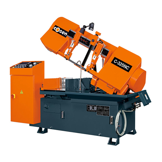
Bandsaw Specialist Bandsaw Specialist Bandsaw Specialist Bandsaw Specialist Instruction Manual Model: C-325NC Programmable Automatic Mass Production Horizontal Bandsaw Manual COSEN MACHINERY INDUSTRIAL CO., LTD... - Page 2 C-325NC. TECHNICAL ADVICE/ SPARE PARTS Please contact the COSEN-representative in your local area in case you need any technical advice or if you want to order spare parts. Instruction Manual: C-325NC Cosen Programmable Automatic Mass Production Horizontal Bandsaw Ver.
-
Page 4: Table Of Contents
TABLE OF CONTENTS SECTION PAGE SAFETY RULES 1-1~8 GENERAL INFORMATIONS INTRODUCTION EQUIPMENT DESCRIPTION 2.2.1 Specification 2.2.2 Identification of Main Parts & Terminology 2-3~4 2.2.3 Emergency Stop Button 2.2.4 Noise Level 2-4~5 2.2.5 Safety Devices and Guards 2-5~6 2.2.6 Specification of Electrical Equipment GUIDE TO THE MANUAL DOCUMENTATION INTRODUCTION... -
Page 5: Table Of Contents
TABLE OF CONTENTS 4.3.2 4-4~5 Control buttons 4.3.3 Blade descend pressure and speed control panel 4.3.4 4-6~17 Human-machine-interface (HMI) touch screen 4-18~19 STANDARD ACCESSORIES OPTIONAL ACCESSORIES 4-19~20 MANUAL MODE 4-21 4.6.1 UNROLLING & INSTALLING THE BLADE 4-21~24 4.6.2 4-24 Adjust the wire brush 4.6.3 4-25 Adjust the saw arm... - Page 6 TABLE OF CONTENTS SYSTEM TROUBLE SHOOTING INTRODUCTION PRECAUTION GENERAL TROUBLES AND SOLUTIONS MINOR TROUBLE SHOOTING BLADE TROUBLES AND SOLUTIONS SAWING PROBLEMS AND SOLUTIONS MINOR TROUBLE SHOOTING THE ADJUSTMENT OF THE FEEDING TABLE 9-6~7 PART LIST 10-1~12...
-
Page 17: Introduction
GENERAL INFORMATION Section 2 SECTION 2 GENERAL INFORMATION I : FOR MACHINE COMMON 2.1 INTRODUCTION This automatic band saw is a model more popular than any other model as witnessed in many countries worldwide. This machine was developed by a group of R&D engineers over a considerable period of time assuring you of the highest efficiency and performance. -
Page 18: Specification
GENERAL INFORMATION Section 2 2.2.1 Specifications Specification of The Machine MODEL C-325NC Round 325 mm MAXIMUM CUTTING Square 325 mm CAPACITY Rectangle (H × × × × W) 325×380 mm SPEED 20 ~ 100 m/ mim (66 ~ 328 fpm) SIZE (L ×... - Page 19 GENERAL INFORMATION Section 2 2.2.2 Indentification of Main Parts & Terminology FIG 2-1 THE SIDE VIEW OF THE MACHINE TOP VIEW DRAWING TOP VIEW DRAWING TOP VIEW DRAWING TOP VIEW DRAWING FIG 2-2...
-
Page 20: Emergency Stop Button
GENERAL INFORMATION Section 2 FRONT SIDE VIEW FRONT SIDE VIEW FRONT SIDE VIEW FRONT SIDE VIEW FIG 2-3 2.2.3 Emergency Stop Button Your machine‘s emergency stop button is designed to be very easy to access. When you press it, it will stop the machine completely to avoid severe injury when an accident occurs. You should press it immediately without hesitation in the following cases: •... - Page 21 GENERAL INFORMATION Section 2 1. Saw blade during cutting or material feed mechanism 2. Wire brush unit 3. Chip conveyor unit 4. Speed reducer 5. Hydraulic motor/pump 6. Belt transmissions variable speed motors 7. Blade motor 8. Coolant Pump 9. Drive wheel 10.
-
Page 22: Specification Of Electrical Equipment
GENERAL INFORMATION Section 2 The saw wheel cover interlock switches located on the two wheel housings are used to assure that the machine will stop whenever the wheel covers are open. This device is to protect users from being cut by the running saw blades. The vise clamp switch is to assure firm clamping of the workpiece. -
Page 23: Guide To The Manual
GENERAL INFORMATION Section 2 2.3 GUIDE TO THE MANUAL S E C T I O N 1 , 2 , 3 , - - - - - - - 1 0 , A P P E N D I X . The instruction manual is divided into ten sections. - Page 24 GENERAL INFORMATION Section 2 Red and white DANGER labels mean immediate hazards that will result in severe personal injury or death. DANGER: Do not operate this machine unless it is completely assembled. DANGER: Before doing any electrical work, disconnect the electrical power with the Main Power Disconnect switch.
-
Page 25: Risk Assessment
GENERAL INFORMATION Section 2 Read all safety labels on the machine Green and white SAFETY INSTRUCTIONS are important reminders that should be read before operating the machine. Please do not make any decisions casually without first reading all safety instructions. 2.6 RISK ASSESSMENT Risk assessment generally takes account of intended use and foreseeable misuse, including process control and maintenance requirements. - Page 26 Section 3 MOVING AND STALLATION...
-
Page 38: Safety Precautions
OPERATING INSTRUCTION SECTION 4 Section 4 OPERATING INSTRUCTION 4.1 SAFETY PRECAUTIONS For your safety, please read and understand the instruction manual before you operate the machine. The operator should always follow these safety guidelines: • The machine should only be used for its designated purpose. •... - Page 39 OPERATING INSTRUCTION SECTION 4 Wet cutting If you choose dry cutting or low-speed cutting, the chips may accumulate in machine parts and may cause operation failure or insulation malfunction. We suggest you choose wet cutting to avoid machine damage. Cutting unknown materials Before cutting an unknown material, consult the material supplier, burn a small amount of chips from the material in a safe place, or follow any other procedure to check if the material is flammable.
-
Page 40: Control Panel
OPERATING INSTRUCTION SECTION 4 4.3 CONTROL PANEL 4.3.1 Control panel The control panel is located on the top of the electrical box. It includes the following function: power system, hydraulic system, cooling system and the human-machine–interface (HMI) and the laser projecting system. - Page 41 OPERATING INSTRUCTION SECTION 4 4.3.2 Control buttons 1. Emergency stop Press this button to stop the machine in an emergency. When the button is pressed, it brings the machine to a full stop. The button locks when pressed. In order to unlock it, please turn the button clockwise.
- Page 42 OPERATING INSTRUCTION SECTION 4 9. Feed forward When this button is pressed, the feeding workbed will move forward. Press and hold the button to feed forward. As soon as the button is released, the feeding workbed will stop moving forward. This button only works when the machine is switched to manual mode “...
-
Page 43: Blade Descend Pressure And Speed Control Panel
OPERATING INSTRUCTION SECTION 4 4.3.3 Blade descend pressure and speed control panel The part of control panel is where cutting pressure and saw bow descend speed can be adjusted. 1. Cutting pressure control knob This pressure control knob is used to adjust the cutting pressure of the blade. - Page 44 Environment No condensation and rust Startup Screen After the power is turned on, Cosen’s logo will appear as the startup screen, followed by the main operation menu.. Main control menu The main control menu includes some operating button that were used on the control panel of the earlier machines.
- Page 45 OPERATING INSTRUCTION SECTION 4 Refer to the table below for descriptions of each function. Item Function Description When the power is turned on, press this button to start the Hydraulic start hydraulic motor. A solid yellow icon indicates the hydraulic system has been turned on.
- Page 46 OPERATING INSTRUCTION SECTION 4 Item Function Description AUTO/Manual mode Use this button to switch between automatic and manual mode. AUTO mode ( ): used to automatically perform continuous cutting jobs. When switched to the AUTO mode, the machine will automatically operate according to the preset parameters.
- Page 47 OPERATING INSTRUCTION SECTION 4 Item Function Description Slow material feeding Used only when under Manual mode. mode When the slow material feeding mode is turned on, the material feeding speed will dramatically reduce to help you position the work piece precisely. System parameter Press this button to set up system parameters.
- Page 48 OPERATING INSTRUCTION SECTION 4 Item Function Description Rear vise status Indicates if the rear vises have clamped and secured the workpiece. indicator When the rear vises have secured the workpiece, the clamping vise icon on the right will turn solid white. Front vise status Indicates if the front vises have clamped and secured the workpiece.
- Page 49 OPERATING INSTRUCTION SECTION 4 Setting parameters • Press to enter parameter setting page. • Key in password and press Enter to set up parameters. Note: All parameters have been set up by the manufacturer. Do not make any random change to these parameters as doing so will affect cutting precision and machine life.
- Page 50 OPERATING INSTRUCTION SECTION 4 Cutting status display & setup When cutting is in operation, press to enter cutting status display and setup page. Page 1 – cutting status display 1 • This page shows the following information (from top to bottom): Feeding length (current feeding vise position) Blade speed...
- Page 51 OPERATING INSTRUCTION SECTION 4 Blade Life Reset - Reset the blade life to zero Press Home to return to the main control menu. Press PGUP to go back to the previous setup page. Press NEXT to go to the next setup page. For machines with optional blade deviation detector installed, additional two command are provided: Deviation - Set deviation tolerance value based on...
- Page 52 OPERATING INSTRUCTION SECTION 4 Cutting program setup When cutting is in operation, press to quickly access the cutting program setup page (the same as page 3 of the cutting status display and setup page) This setup page is the same as page 3 of the cutting status display and setup page.
- Page 53 OPERATING INSTRUCTION SECTION 4 PLC Monitor Shows all signals of the PLC system. Error report Page 1 – error report • Lists a historical report of the errors and the time of occurrence. • Press Home to return to the main control menu. •...
- Page 54 OPERATING INSTRUCTION SECTION 4 Error Error Description Solution Code M300 Front vises not clamping Check if the queen valve works M301 Rear vises not clamping Check if the queen valve works M303 Lower limit switch error Check if the lower limit switch works M304 Hydraulic motor not starting Check if the hydraulic motor works...
-
Page 55: Standard Accessories
OPERATING INSTRUCTION SECTION 4 4.4 STANDARD ACCESSORIES Blade tension device This blade tension device equipped with hydraulic cylinder provides appropriate tension to the saw blade. To tighten the saw blade, turn the selector to Upon saw blade breakage, the safety device will activate and automatically stop all machine operation. -
Page 56: Optional Accessories
OPERATING INSTRUCTION SECTION 4 Quick approach device This device allows the blade to quickly descend to just right above the material to save you operation time. Split front vises The spilt vises are a clever design to make sure your workpiece is tightly clamped by the two vises from both sides of the blade, maximizing stability and cutting precision. - Page 57 OPERATING INSTRUCTION SECTION 4 Vibration Damper The vibration damper can be assembled to the left saw arm. This optional accessory is extremely useful in reducing the high- frequency noise produced when cutting large-sized material. Chip conveyor Chip conveyor is a spiral device to bring chips out during cutting. Note: As a regular maintenance, remove the chip conveyor and clean all chip deposits inside.
-
Page 58: Manual Mode
OPERATING INSTRUCTION SECTION 4 4.6 MANUAL MODE 4.6.1 UNROLLING & INSTALLING THE BLADE Caution: Always wear leather gloves and protection glasses when handling a blade. Unrolling the blade Please follow the procedures illustrated below. Fig 4 – 3 Unroll and roll the blade 4-21... - Page 59 OPERATING INSTRUCTION SECTION 4 Installing a new blade Step 1 - Select the most suitable saw blade for your workpiece considering the size, shape and material. Step 2 - Turn on the machine power by switching to ON. Step 3 - Switch to manual ( ) mode. Step 4 - Press the saw bow up button and elevate the saw bow until the right insert holder is clear of the front fixed vise (see below picture).
- Page 60 OPERATING INSTRUCTION SECTION 4 Step 8 - Loosen the left and right carbide inserts by loosening the “lock nut” shown below. Step 9 - Open the wire brush cover. Loosen the lock level and lower the wire brush. Step 10 - If necessary, clean the carbide inserts before installing a new saw blade. Step 11 - Place the new blade around the idle wheel and the drive wheel Step 12 - Insert the blade into the left and right tungsten carbide inserts.
- Page 61 OPERATING INSTRUCTION SECTION 4 Step 15 - Turn the tension controller handle to [ ] position to obtain blade tension. Step 16 - Make sure the sides of the blade are in close contact with the carbide inserts and then tightening the “lock nut.
-
Page 62: Placing Workpiece Onto Workbed
OPERATING INSTRUCTION SECTION 4 4.6.3 Adjusting saw arm Adjust the blade guide (guide arm) position based on the size of your workpiece: Step 1 – Loosen the inserts by unlocking the lock nut. Step 2 – Loosen the blade guide locking handle. Then adjust the guide arm to a position suitable for your workpiece size. -
Page 63: Positioning Workpiece For Cutting
OPERATING INSTRUCTION SECTION 4 4.6.5 Positioning workpiece for cutting Follow these steps to position your workpiece: Step Action Press the rear vise clamp button until the workpiece is securely rear vises clamp material clamped. Move the vertical alignment rollers toward workpiece until it align vertical rollers stands against the workpiece. -
Page 64: Adjusting Blade Speed
OPERATING INSTRUCTION SECTION 4 4.6.6 Adjusting blade speed Step 1 – Set the flow control to “0” position. Step 2 – Press the saw blade start button to start the blade.. Step 3 – Turn the blade speed control knob to adjust the blade speed. The blade speed should be adjusted based on the size and the material of the workpiece. -
Page 65: Installation Procedure
OPERATING INSTRUCTION SECTION 4 (1) Reduce the blade speed to one-half of its normal setting. (2) Lengthen the cutting time to 2-3 times of what is normally required. (3) The complete break-in operation requires cutting on a 645 mm (25.4 square inches) section for 5 times. - Page 66 OPERATING INSTRUCTION SECTION 4 Step 2 – Connect the top clamp hoses to the pressure joints on the vise hydraulic cylinders. Step 3 – Position the workpiece for bundle cutting. Note the allowable clamping width and height. Clamping width: 190 – 300 mm (7.5 – 11.8 inch) Clamping height: 70 –...
-
Page 67: Test Run The Machine
OPERATING INSTRUCTION SECTION 4 4.8 TEST RUN THE MACHINE Test-running this machine can ensure good machine performance in the future. We suggest you run the following tests on the machine before first use: Testing machine performance: Turn on the power and run a basic performance test after you finish installing the machine. Follow these steps to test machine performance: Step 1 –... -
Page 68: Terminating A Cutting Operation
OPERATING INSTRUCTION SECTION 4 Step 4 – Clamp the workpiece. Step 5 – Turn the cutting pressure control knob to adjust blade descending speed according to the material. Step 6 – Adjust blade descend speed control knob to obtain a suitable blade descend speed for your material. - Page 69 Section 5 ELECTRICAL SYSTEM...
- Page 70 ELECTRICAL SYSTEM Section 5 SECTION 5 ELECTRICAL SYSTEM 5.1 INTRODUCTION This section will introduce the machine’s electric system diagram in easy understand way. 5.2 ELECTRICAL CIRCUIT DIAGRAMS As mentioned earlier at the beginning of the section. The electric circuit diagrams shown here are: The electric circuit diagram of the system : Fig 5-1 control panel layout Fig 5-2 circuit board layout...
- Page 71 ELECTRICAL SYSTEM Section 5 Fig.5-1 control panel layout...
- Page 72 ELECTRICAL SYSTEM Section 5 Fig.5-2 circuit board layout...
- Page 73 ELECTRICAL SYSTEM Section 5 Fig.5-3 power supply layout...
- Page 74 ELECTRICAL SYSTEM Section 5 Fig.5-4-1 PLC I/O layout...
- Page 76 HYDRAULIC SYSTEM Section 6 SECTION 6 HYDRAULIC SYSTEM 6.1 INTRODUCTION The band saw model for your device is a hydraulic driven automatic machine. Most of the movement of the machine elements are powered by the hydraulic system. In the front of drive wheel installed one set of tension adjusting part, used on adjusting the tention as saw blade required.
- Page 77 HYDRAULIC SYSTEM Section 6 Fig 6-1 HYDRAULIC CIRCULIC...
- Page 97 Section 10 PART LIST...
- Page 98 C-325NC 10-1...
- Page 99 10-2...
- Page 100 10-3...
- Page 101 10-4...
- Page 102 10-5...
- Page 103 10-6...
- Page 104 10-7...
- Page 105 10-8...
- Page 106 10-9...
- Page 107 10-10...
- Page 108 10-11...
- Page 109 10-12...
Need help?
Do you have a question about the C-325NC and is the answer not in the manual?
Questions and answers