Table of Contents
Advertisement
Available languages
Available languages
Quick Links
Programmable Controllers
Installation Manual for Power Supply
Modules L61P, L63P
Art.no.: ENG, Version A, 06042011
Safety Information
For qualified staff only
This manual is only intended for use by properly trained and qualified electri-
cal technicians who are fully acquainted with automation technology safety
standards. All work with the hardware described, including system design,
installation, setup, maintenance, service and testing, may only be performed
by trained electrical technicians with approved qualifications who are fully
acquainted with the applicable automation technology safety standards and
regulations.
Proper use of equipment
The programmable controllers (PLC) of the MELSEC L series are only intended
for the specific applications explicitly described in this manual or the manuals
listed below. Please take care to observe all the installation and operating
parameters specified in the manual. All products are designed, manufactured,
tested and documented in agreement with the safety regulations. Any modi-
fication of the hardware or software or disregarding of the safety warnings
given in this manual or printed on the product can cause injury to persons or
damage to equipment or other property. Only peripherals and expansion
equipment specifically recommended and approved by Mitsubishi Electric
may be used with the programmable controllers of the MELSEC L series. Any
other use or application of the products is deemed to be improper.
Relevant safety regulations
All safety and accident prevention regulations relevant to your specific appli-
cation must be observed in the system design, installation, setup, mainte-
nance, servicing and testing of these products.
In this manual special warnings that are important for the proper and safe use
of the products are clearly identified as follows:
DANGER:
P
Personnel health and injury warnings.
Failure to observe the precautions described here can result
in serious health and injury hazards.
E
CAUTION:
Equipment and property damage warnings.
Failure to observe the precautions described here can result
in serious damage to the equipment or other property.
Further information
The following manuals contain further information about the module:
● Instruction leaflet "Before Using the Product" for L61P
● Instruction leaflet "Before Using the Product" for L63P
● MELSEC L CPU Module User's Manual
(Hardware Design, Maintenance and Inspection)
● MELSEC-Q L Programming Manual
● Safety Guidelines for MELSEC L CPU
These manuals are available free of charge through the internet
(www.mitsubishi-automation.com).
If you have any questions concerning the installation, configuration or opera-
tion of the equipment described in this manual, please contact your relevant
sales office or department.
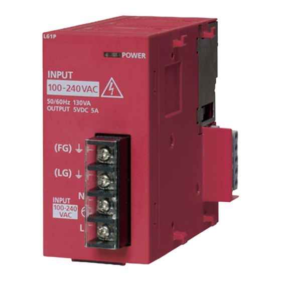
External Dimensions and Part Names
³
4
95
109
All dimensions are in "mm".
·
»
¿
´
²
No.
Description
³
DIN rail mounting hook
Indicates the power supply status
On:
Normal operation
·
POWER LED
Off:
Power is not supplied,
power has failed, or
the hardware has failed.
Ground terminal
»
FG terminal
This terminal is connected to the shield pattern of
the printed-circuit board.
Ground terminal for the power supply filter
¿
LG terminal
For AC input, it has one-half the potential of the
input voltage
´
Power input terminals
²
Serial number plate
Installation and Wiring
P
DANGER
Turn off all phases of the power supply for the PLC and other external
sources before starting the installation or wiring work.
E
CAUTION
● Use the product in the environment within the general specifications
described in the MELSEC L CPU Module User's Manual. Never use the
product in areas with dust, oily smoke, conductive dusts, corrosive or
flammable gas, vibrations or impacts, or expose it to high tempera-
ture, condensation, or wind and rain.
45
● When drilling screw holes or wiring, cutting chips or wire chips should
not enter ventilation slits. Such an accident may cause fire, failure or
malfunction.
● A protective film is attached onto the module top to prevent foreign
matter such as wire chips entering the module during wiring. Do not
remove the film during wiring. Remove it for heat dissipation before
system operation.
● Before handling modules, touch a grounded metal object to discharge
the static electricity from the human body. Not doing so may cause
failure or malfunctions of the module.
Mounting
E
CAUTION
● Modules must be mounted on a DIN rail.
● Connect an END cover on the last module on the right side.
● Do not drop the module or subject it to heavy impact.
● Do not open or modify a module. Doing so can cause a failure, mal-
function, injury or fire.
● Do not touch the conductive parts of the module directly.
● To interconnect modules, engage the respective connectors and se-
curely lock the module joint levers. Incorrect interconnection may
cause malfunction, failure, or drop of the module.
Connecting the modules
The procedure for connecting modules is shown with an example of how to
connect the L02CPU with the L61P.
Release
Lock
Mounting the modules on a DIN rail
Mount stoppers on the DIN-rail beside the leftmost and rightmost module,
to avoid lateral sliding.
NOTE
Do not slide modules from the edge of the DIN rail when mounting. Doing so
may damage the metal part located on the back of the module.
Wiring
E
● Do not lay signal cables close to the main circuit, high-voltage power
lines, or load lines. Otherwise effects of noise or surge induction are
likely to take place. Keep a safe distance of more than 100 mm from
the above when wiring.
● Wire cables of the power supply for the programmable controller, I/O
power supply, and motor power supply separately.
To release the module joint
Always use a solderless terminal for wiring to the terminal block on a power
levers located at the top and
supply module. To prevent a short when screws come loose, always use a sol-
derless terminal with insulation sleeve of 0.8mm or less in thickness.
bottom of the L02CPU:
Slide the levers toward the
Solderless terminals with
Terminal block
front side of the module.
insulation sleeve
Tighen the screws of the module using torque within the following ranges.
Loose screws may cause short circuits, mechanical failures or malfunction.
Screw
Terminal block mounting screw (M3.5 screw)
Insert the connector of the
power supply module into
that of the CPU module so
t h a t t h e y a r e s e c u r e l y
P
engaged.
After installation and wiring, attach the included terminal cover to the
module before turning it on for operation. Failure to do so may result in
electric shock.
To lock the module joint
levers:
Slide the levers toward the
back side of the module.
Make sure that the mod-
u l e s a re s e c u r e l y c o n -
nected.
Mitsubishi Electric Europe B.V. /// FA - European Business Group ///
Germany /// Tel.: +49(0)2102-4860 /// Fax: +49(0)2102-4861120 ///
www.mitsubishi-automation.com
Pull down DIN rail hooks on
the back of the modules
until they click.
Hang the upper tabs of the
modules on a DIN rail, and
push the modules in posi-
tion.
Lock the DIN rail hooks to
the DIN rail to secure the
modules in the position.
Pull the hooks up until they
c l i c k . I f t h e h o o k s a r e
beyond the reach, use a tool
such as a driver.
CAUTION
Up to two solderless terminals
can be connected to one terminal
block.
Torque
0.66 to 0.89 Nm
DANGER
Advertisement
Table of Contents

Related Manuals for Mitsubishi Electric L61P


Summary of Contents for Mitsubishi Electric L61P
- Page 1 Make sure that the mod- u l e s a re s e c u r e l y c o n - nected. Mitsubishi Electric Europe B.V. /// FA - European Business Group /// Germany /// Tel.: +49(0)2102-4860 /// Fax: +49(0)2102-4861120 /// www.mitsubishi-automation.com...
- Page 2 Sollten sich Fragen zur Installation, Programmierung und Betrieb der Steue- Prüfen Sie, ob die Module Mitsubishi Electric Europe B.V. /// FA - European Business Group /// rungen der MELSEC L-Serie ergeben, zögern Sie nicht, Ihr zuständiges Ver- fest miteinander verbun- Germany /// Tel.: +49(0)2102-4860 /// Fax: +49(0)2102-4861120 ///...
- Page 3 Si vous avez des questions concernant la programmation et le fonctionne- ment du matériel décrit dans ce manuel, contactez votre bureau de vente res- ponsable ou votre distributeur. Mitsubishi Electric Europe B.V. /// FA - European Business Group /// Germany /// Tel.: +49(0)2102-4860 /// Fax: +49(0)2102-4861120 /// www.mitsubishi-automation.com...
-
Page 4: Specifications
Inrush current 20 A, within 8 ms ● Die SPS sollte nach Möglichkeit unabhängig von anderen Gerä- (Input 24 V DC) AC power supply (L61P) / ten geerdet werden. Sollte eine eigenständige Erdung nicht AC Spannungsversorgung (L61P) / Rated output current... -
Page 5: Avvertenze Di Sicurezza
0,66 fino a 0,89 Nm Ulteriori informazioni in merito alle apparecchiature sono riportate nei manuali seguenti: ● Pieghevole di istruzioni “Prima di utilizzare il prodotto” per L61P PERICOLO ● Pieghevole di istruzioni “Prima di utilizzare il prodotto” per L63P ● Manuale utente modulo MELSEC L CPU Al termine di montaggio e cablaggio, applicare il coperchio morsettiera ●... - Page 6 Se visualiza el estado de la alimentación de tensión. los bien con las palancas de bloqueo. Si los módulos no están bien uni- o de ampliación recomendados por MITSUBISHI ELECTRIC. Todo empleo o aplica- Operación normal de trabajo. La distancia mínima con respecto a ese tipo de líneas tiene ·...
- Page 7 При возникновении вопросов по установке, программированию и экс- плуатации контроллеров серии L, обратитесь в ваше региональное торговое Mitsubishi Electric Europe B.V. /// FA - European Business Group /// представительство или к региональному дистрибьютору. Germany /// Tel.: +49(0)2102-4860 /// Fax: +49(0)2102-4861120 ///...
-
Page 8: Specifiche Tecniche
● En la medida de lo posible, el PLC debe ponerse a tierra sepa- 100 A, Inferiori 1 ms ный трансформатор. Fuente de alimentación AC (L61P)/ Corrente di spunto 20 A, Inferiori 8 ms radamente de otros aparatos. En caso de que no fuera posible (Ingresso 24 V DC) Источник... - Page 9 Jeśli pojawią się jakiekolwiek pytania związane z instalowaniem, programowaniem i działaniem sterowników z serii MELSEC L, prosimy o bezzwłoczne skontaktowanie Mitsubishi Electric Europe B.V. /// FA - European Business Group /// się z lokalnym biurem sprzedaży lub dystrybutorem. Germany /// Tel.: +49(0)2102-4860 /// Fax: +49(0)2102-4861120 ///...
- Page 10 üzembe helyezése, beállítása, ● A programozható vezérlő tápegységének vezetékeit, az I/O és a motor meghibásodott. A modulok összekapcsolásának példája az L02CPU és az L61P összekapcsolá- karbantartása, javítása és ellenőrzése során. sával van illusztrálva.
- Page 11 Zkontrolu- jte, jestli jsou oba moduly pevně spojeny. Mitsubishi Electric Europe B.V. /// FA - European Business Group /// Germany /// Tel.: +49(0)2102-4860 /// Fax: +49(0)2102-4861120 /// www.mitsubishi-automation.com...
-
Page 12: Dane Techniczne
24 V DC) AC/DC tápegység (L61P)/ ● A földelési ellenállás maximális értéke 100 . Napětí AC/DC napájecí napětí (L61P) Znamionowa wartość ● Amennyiben lehetséges, a PLC-t más berendezésektől külön- prądu wyjściowego (5 V DC) választva földelje. Ha különálló földelő csatlakozás kialakítása 100–240 V AC/...