Table of Contents
Advertisement
Advertisement
Table of Contents

Related Manuals for Mitsubishi Electric RJ71PN92


Summary of Contents for Mitsubishi Electric RJ71PN92
- Page 1 MELSEC iQ-R PROFINET IO Controller Module User's Manual (Startup) -RJ71PN92...
-
Page 3: Safety Precautions
SAFETY PRECAUTIONS (Read these precautions before using this product.) Before using this product, please read this manual and the relevant manuals carefully and pay full attention to safety to handle the product correctly. The precautions given in this manual are concerned with this product only. For the safety precautions of the programmable controller system, refer to the MELSEC iQ-R Module Configuration Manual. - Page 4 [Design Precautions] WARNING ● Configure safety circuits external to the programmable controller to ensure that the entire system operates safely even when a fault occurs in the external power supply or the programmable controller. Failure to do so may result in an accident due to an incorrect output or malfunction. (1) Emergency stop circuits, protection circuits, and protective interlock circuits for conflicting operations (such as forward/reverse rotations or upper/lower limit positioning) must be configured external to the programmable controller.
- Page 5 [Design Precautions] WARNING ● Especially, when a remote programmable controller is controlled by an external device, immediate action cannot be taken if a problem occurs in the programmable controller due to a communication failure. To prevent this, configure an interlock circuit in the program, and determine corrective actions to be taken between the external device and CPU module in case of a communication failure.
- Page 6 [Installation Precautions] WARNING ● Shut off the external power supply (all phases) used in the system before mounting or removing the module. Failure to do so may result in electric shock or cause the module to fail or malfunction. [Installation Precautions] CAUTION ●...
- Page 7 [Wiring Precautions] CAUTION ● Individually ground the FG and LG terminals of the programmable controller with a ground resistance of 100 ohms or less. Failure to do so may result in electric shock or malfunction. ● Use applicable solderless terminals and tighten them within the specified torque range. If any spade solderless terminal is used, it may be disconnected when the terminal screw comes loose, resulting in failure.
- Page 8 [Startup and Maintenance Precautions] WARNING ● Do not touch any terminal while power is on. Doing so will cause electric shock or malfunction. ● Correctly connect the battery connector. Do not charge, disassemble, heat, short-circuit, solder, or throw the battery into the fire. Also, do not expose it to liquid or strong shock. Doing so will cause the battery to produce heat, explode, ignite, or leak, resulting in injury and fire.
- Page 9 [Startup and Maintenance Precautions] CAUTION ● When connecting an external device with a CPU module or intelligent function module to modify data of a running programmable controller, configure an interlock circuit in the program to ensure that the entire system will always operate safely. For other forms of control (such as program modification, parameter change, forced output, or operating status change) of a running programmable controller, read the relevant manuals carefully and ensure that the operation is safe before proceeding.
- Page 10 [Startup and Maintenance Precautions] CAUTION ● Startup and maintenance of a control panel must be performed by qualified maintenance personnel with knowledge of protection against electric shock. Lock the control panel so that only qualified maintenance personnel can operate it. ●...
-
Page 11: Conditions Of Use For The Product
CONDITIONS OF USE FOR THE PRODUCT (1) Mitsubishi programmable controller ("the PRODUCT") shall be used in conditions; i) where any problem, fault or failure occurring in the PRODUCT, if any, shall not lead to any major or serious accident; ii) where the backup and fail-safe function are systematically or automatically provided outside of the PRODUCT for the case of any problem, fault or failure occurring in the PRODUCT. -
Page 12: Introduction
DIRECTIVES Method of ensuring compliance To ensure that Mitsubishi Electric programmable controllers maintain EMC and Low Voltage Directives when incorporated into other machinery or equipment, certain measures may be necessary. Please refer to one of the following manuals. • MELSEC iQ-R Module Configuration Manual •... -
Page 13: Table Of Contents
Communication Example of the RJ71PN92 and an IO Device ....... . -
Page 14: Relevant Manuals
This manual does not include information on the module function blocks. For details, refer to the Function Block Reference for the module used. e-Manual refers to the Mitsubishi Electric FA electronic book manuals that can be browsed using a dedicated tool. -
Page 15: Terms
A generic term for the MELSEC iQ-R series CPU modules Cycle time Time required for one cycle of data exchange between the RJ71PN92 and each IO device Device A device (X, Y, M, D, or others) in a CPU module... -
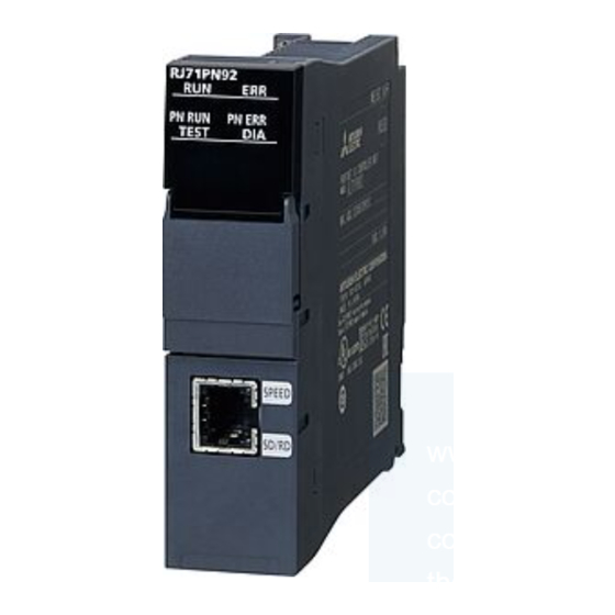
Page 16: Chapter 1 Part Names
PART NAMES This section describes the names of each part of the RJ71PN92. Name Description RUN LED Indicates the operating status. On: Normal operation Flashing: Initial processing Off: Error ( MELSEC iQ-R PROFINET IO Controller Module User's Manual (Application)) ERR LED Indicates the error status of the module. - Page 17 MEMO 1 PART NAMES...
-
Page 18: Chapter 2 Specifications
SPECIFICATIONS Performance Specifications The following table lists the performance specifications of the RJ71PN92. Item Description Data exchange Maximum input data length per network 4096 words Maximum output data length per network 4096 words Maximum input data length per IO device... - Page 19 MEMO 2 SPECIFICATIONS 2.1 Performance Specifications...
-
Page 20: Chapter 3 Function List
FUNCTION LIST The following tables list the functions of the RJ71PN92. For details on the functions, refer to the following. MELSEC iQ-R PROFINET IO Controller Module User's Manual (Application) Data communications Function Description Data exchange function Performs data exchange between the RJ71PN92 and IO devices in a specified period. - Page 21 MEMO 3 FUNCTION LIST...
-
Page 22: Chapter 4 Procedures Before Operation
This chapter describes the procedures before operation. Mounting the module to the base unit The RJ71PN92 has no module fixing hooks. For how to mount and remove a module without module fixing hooks to/from the base unit, refer to the following. - Page 23 MEMO 4 PROCEDURES BEFORE OPERATION...
-
Page 24: Chapter 5 System Configuration
SYSTEM CONFIGURATION PROFINET Configuration PROFINET consists of an RJ71PN92 (1) and IO devices (2). In PROFINET, other PROFINET IO controllers or external devices that perform TCP/IP communications can be used with the devices above on the same network. 5 SYSTEM CONFIGURATION... -
Page 25: Applicable Cpu Modules
*1 This model can be used with the R04CPU, R08CPU, R16CPU, R32CPU, and R120CPU. *2 The RJ71PN92 cannot be mounted to the base unit (including an extension base unit) which the NCCPU is mounted. If mounted, an error occurs in the control CPU of the RJ71PN92 and the NCCPU. -
Page 26: Available Software Packages
The profile is data stored the information (such as a model name) of connected devices. Profile of the RJ71PN92 are automatically registered in GX Works3 during the installation of GX Configurator-PN. If GX Works3 is installed on the condition that GX Configurator-PN is already installed, the RJ71PN92 cannot be added in GX Works3. -
Page 27: Chapter 6 Wiring
This section describes connection and disconnection of the Ethernet cable. Connecting the cable Push the Ethernet cable connector into the RJ71PN92 until it clicks. Pay attention to the connector's direction. Lightly pull it to check that it is securely connected. -
Page 28: Wiring Products
A communication error may occur due to high-frequency noise from devices other than a programmable controller in a given connection environment. The following describes countermeasures to be taken on the RJ71PN92 side to avoid high-frequency noise influence. [Wiring] • Do not install cables together with the main circuit lines or power cables. -
Page 29: Chapter 7 Communication Example
IO Device This section provides an example for data exchange between the RJ71PN92 and an IO device. System configuration example The following system configuration is used to explain data exchange between the RJ71PN92 and an IO device. System configuration GX Works3... -
Page 30: Setting Parameters
Click the [OK] button to add the module labels of the CPU module. Set the RJ71PN92 as follows. [Navigation window] [Parameter] [Module Information] Right-click [Add New Module] 7 COMMUNICATION EXAMPLE 7.1 Communication Example of the RJ71PN92 and an IO Device... - Page 31 Set the items in "Basic Setting" as follows. [Navigation window] [Parameter] [Module Information] [RJ71PN92] [Module Parameter] [Basic Setting] PROFINET module setting Start GX Configurator-PN from the engineering tool. [Navigation window] [Parameter] [Module Information] [RJ71PN92] [PROFINET Module Setting] Open the "GSDML Management"...
- Page 32 Click the [Browse] button. Select the GSDML file and click the [Open] button. Click the [Next] button. 7 COMMUNICATION EXAMPLE 7.1 Communication Example of the RJ71PN92 and an IO Device...
- Page 33 Select IM151-3 PN V2.0 in "Device Library" to add it in the network configuration setting. Select IM151-3 PN V2.0 in "Device Library". [Library] [Insert in Configuration] 7 COMMUNICATION EXAMPLE 7.1 Communication Example of the RJ71PN92 and an IO Device...
- Page 34 PN V2.0 is added in the network configuration setting from "Device Library".) • [General Configuration] tab • [Module Configuration] tab Save the set project of GX Configurator-PN. [File] [Save] Exit GX Configurator-PN. [File] [Exit] 7 COMMUNICATION EXAMPLE 7.1 Communication Example of the RJ71PN92 and an IO Device...
- Page 35 [Navigation window] [Parameter] [Module Information] [RJ71PN92] Right-click [Update PROFINET Label] Convert or rebuild programs. [Convert] [Convert] or [Rebuild All] Write the set parameters to the CPU module and the RJ71PN92. Then reset the CPU module or power off and on the system. [Online] [Write to PLC] In this example, default values are used for parameters that are not shown above.
-
Page 36: Checking The Network Status
Checking the network status Check whether the RJ71PN92 and IO device communicate with each other normally. Communications are performed normally if the status of LEDs and corresponding bits of each IO device in buffer memory areas are as follows after the program execution. -
Page 37: Program Example For Data Exchange
W1100.0 glRJ71PN92_1.SLV001SLOT002DataStructIn.SLOT002_BIT_1 W1100.1 glRJ71PN92_1.SLV001SLOT002DataStructIn.SLOT002_BIT_2 W1100.2 glRJ71PN92_1.SLV001SLOT002DataStructIn.SLOT002_BIT_3 W1100.3 Label to be defined Define global labels as shown below: (7) Program to process I/O data to IO device 1 7 COMMUNICATION EXAMPLE 7.1 Communication Example of the RJ71PN92 and an IO Device... - Page 38 MEMO 7 COMMUNICATION EXAMPLE 7.1 Communication Example of the RJ71PN92 and an IO Device...
-
Page 39: Appendix
APPENDIX Appendix 1 External Dimensions This section describes the external dimensions of the RJ71PN92. 27.8 (Unit: mm) APPENDIX Appendix 1 External Dimensions... - Page 40 MEMO APPENDIX Appendix 1 External Dimensions...
- Page 41 MEMO APPENDIX Appendix 1 External Dimensions...
-
Page 42: Index
INDEX ....18 ..... 16 Alarm acquisition function Transmission method . - Page 43 MEMO...
-
Page 44: Revisions
Japanese manual number: SH-081677-B This manual confers no industrial property rights of any other kind, nor does it confer any patent licenses. Mitsubishi Electric Corporation cannot be held responsible for any problems involving industrial property rights which may occur as a result of using the contents noted in this manual. -
Page 45: Warranty
WARRANTY Please confirm the following product warranty details before using this product. 1. Gratis Warranty Term and Gratis Warranty Range If any faults or defects (hereinafter "Failure") found to be the responsibility of Mitsubishi occurs during use of the product within the gratis warranty term, the product shall be repaired at no cost via the sales representative or Mitsubishi Service Company. -
Page 46: Trademarks
TRADEMARKS PROFINET is a trademark of PROFIBUS Nutzerorganisation e.V. The company names, system names and product names mentioned in this manual are either registered trademarks or trademarks of their respective companies. In some cases, trademark symbols such as ' ' or ' ' are not specified in this manual. - Page 48 SH(NA)-081679ENG-B(1809)MEE MODEL: RJ71PN92-U-IN-E MODEL CODE: 13JX59 HEAD OFFICE : TOKYO BUILDING, 2-7-3 MARUNOUCHI, CHIYODA-KU, TOKYO 100-8310, JAPAN NAGOYA WORKS : 1-14 , YADA-MINAMI 5-CHOME , HIGASHI-KU, NAGOYA , JAPAN When exported from Japan, this manual does not require application to the Ministry of Economy, Trade and Industry for service transaction permission.