
Related Manuals for Mitsubishi Electric RJ72GF15-T2


Summary of Contents for Mitsubishi Electric RJ72GF15-T2
- Page 1 MELSEC iQ-R CC-Link IE Field Network Remote Head Module User's Manual (Startup) -RJ72GF15-T2...
-
Page 3: Safety Precautions
SAFETY PRECAUTIONS (Read these precautions before using this product.) Before using this product, please read this manual and the relevant manuals carefully and pay full attention to safety to handle the product correctly. The precautions given in this manual are concerned with this product only. For the safety precautions of the programmable controller system, refer to the MELSEC iQ-R Module Configuration Manual. - Page 4 [Design Precautions] WARNING ● Configure safety circuits external to the programmable controller to ensure that the entire system operates safely even when a fault occurs in the external power supply or the programmable controller. Failure to do so may result in an accident due to an incorrect output or malfunction. (1) Emergency stop circuits, protection circuits, and protective interlock circuits for conflicting operations (such as forward/reverse rotations or upper/lower limit positioning) must be configured external to the programmable controller.
- Page 5 [Design Precautions] WARNING ● If a communication cable is disconnected, the network may be unstable, resulting in a communication failure of multiple stations. Configure an interlock circuit in the program to ensure that the entire system will always operate safely even if communications fail. Failure to do so may result in an accident due to an incorrect output or malfunction.
- Page 6 [Design Precautions] CAUTION ● Do not install the control lines or communication cables together with the main circuit lines or power cables. Keep a distance of 100mm or more between them. Failure to do so may result in malfunction due to noise. ●...
- Page 7 [Installation Precautions] CAUTION ● Use the programmable controller in an environment that meets the general specifications in the Safety Guidelines included with the base unit. Failure to do so may result in electric shock, fire, malfunction, or damage to or deterioration of the product. ●...
- Page 8 [Wiring Precautions] CAUTION ● Individually ground the FG and LG terminals of the programmable controller with a ground resistance of 100 ohms or less. Failure to do so may result in electric shock or malfunction. ● Use applicable solderless terminals and tighten them within the specified torque range. If any spade solderless terminal is used, it may be disconnected when the terminal screw comes loose, resulting in failure.
- Page 9 [Startup and Maintenance Precautions] WARNING ● Do not touch any terminal while power is on. Doing so will cause electric shock or malfunction. ● Correctly connect the battery connector. Do not charge, disassemble, heat, short-circuit, solder, or throw the battery into the fire. Also, do not expose it to liquid or strong shock. Doing so will cause the battery to produce heat, explode, ignite, or leak, resulting in injury and fire.
- Page 10 [Startup and Maintenance Precautions] CAUTION ● Startup and maintenance of a control panel must be performed by qualified maintenance personnel with knowledge of protection against electric shock. Lock the control panel so that only qualified maintenance personnel can operate it. ●...
- Page 11 [Transportation Precautions] CAUTION ● When transporting lithium batteries, follow the transportation regulations. For details on the regulated models, refer to the MELSEC iQ-R Module Configuration Manual. ● The halogens (such as fluorine, chlorine, bromine, and iodine), which are contained in a fumigant used for disinfection and pest control of wood packaging materials, may cause failure of the product.
-
Page 12: Conditions Of Use For The Product
CONDITIONS OF USE FOR THE PRODUCT (1) Mitsubishi programmable controller ("the PRODUCT") shall be used in conditions; i) where any problem, fault or failure occurring in the PRODUCT, if any, shall not lead to any major or serious accident; ii) where the backup and fail-safe function are systematically or automatically provided outside of the PRODUCT for the case of any problem, fault or failure occurring in the PRODUCT. -
Page 13: Introduction
INTRODUCTION Thank you for purchasing the Mitsubishi Electric MELSEC iQ-R series programmable controllers. This manual describes the specifications, procedures before operation, system configuration, wiring, and communication examples of the relevant product listed below. Before using this product, please read this manual and the relevant manuals carefully and develop familiarity with the functions and performance of the MELSEC iQ-R series programmable controller to handle the product correctly. -
Page 14: Compliance With Emc And Low Voltage Directives
DIRECTIVES Method of ensuring compliance To ensure that Mitsubishi Electric programmable controllers maintain EMC and Low Voltage Directives when incorporated into other machinery or equipment, certain measures may be necessary. Please refer to one of the following manuals. • MELSEC iQ-R Module Configuration Manual •... -
Page 15: Table Of Contents
CONTENTS SAFETY PRECAUTIONS ..............1 CONDITIONS OF USE FOR THE PRODUCT . -
Page 16: Relevant Manuals
• Installation For details, refer to the following. MELSEC iQ-R Module Configuration Manual e-Manual refers to the Mitsubishi Electric FA electronic book manuals that can be browsed using a dedicated tool. e-Manual has the following features: • Required information can be cross-searched in multiple manuals. -
Page 17: Terms
This station responds to a transient transmission request from another station. Remote head module The abbreviation for the RJ72GF15-T2 CC-Link IE Field Network remote head module Remote I/O station A station that exchanges I/O signals (bit data) with the master station by cyclic transmission... - Page 18 Term Description Remote register (RWw) Word data output from the master station to a slave station (For some areas in a local station, data are output in the opposite direction.) SIL2 function module Another name for the R6PSFM. This module is used with the SIL2 Process CPU as a pair and performs safety control. The module can only be paired with the SIL2 Process CPU.
-
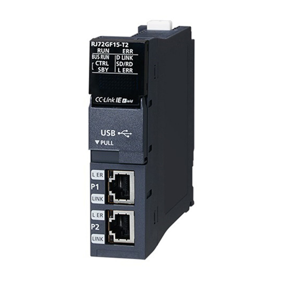
Page 19: Chapter 1 Part Names
PART NAMES This chapter describes the part names of the remote head module. (10) (11) (12) (13) (15) (14) Name Description RUN LED Indicates the operating status of the CPU module and the error level. ● RUN LEDERR LED status ERR LED Onoff: Normal operation Onon: Minor error... - Page 20 Name Description CTRL LED Indicates the status of the control system when the remote head module is redundant. (Always off when the module is not redundant.) On: Operating as the control system (system switching enabled state) Flashing: Operating as the control system (system switching disabled state) Off: Not operating as a control system SBY LED Indicates the status of the standby system and memory copy when the remote head module is redundant.
- Page 21 Name Description (13) Ethernet port (P2) PORT2 connector for CC-Link IE Field Network. Connect an Ethernet cable. For wiring methods and wiring precautions, refer to the following. ( Page 31 WIRING) L ER LED Same as the P1 connector LINK LED (14) Switch/USB cover A cover for a switch and USB port.
-
Page 22: Chapter 2 Performance Specifications
PERFORMANCE SPECIFICATIONS This chapter describes the performance specifications of the remote head module. For the specifications of CC-Link IE Field Network, refer to the following. User's manual for the master/local module used Item Specifications Maximum number of link points 2K points (2048 points, 256 bytes) per station 2K points (2048 points, 256 bytes) - Page 23 *1 This is the maximum number of points that can be assigned to the actual module in "I/O Assignment Setting" in the [I/O Assignment] tab of the "System Parameter" window of the engineering tool. *2 These are the maximum points that can be handled in the remote head module. The number of points actually used differs depending on the module used.
-
Page 24: Chapter 3 Function List
FUNCTION LIST The following table lists the functions of the remote head module. For details on the functions, refer to the following. MELSEC iQ-R CC-Link IE Field Network Remote Head Module User's Manual (Application) Function Description Cyclic transmission Uses the input and output data of the modules connected to the remote head module just like those of the master station. - Page 25 *1 When the network synchronization communication is performed with the master station, set the inter-module synchronization cycle to any of the following. 0.888ms 1.777ms 3.555ms 0.8 to 10.0ms (set in increments of 0.05ms) 3 FUNCTION LIST...
-
Page 26: Chapter 4 Procedures Before Operation
PROCEDURES BEFORE OPERATION This chapter describes the procedures before operation. Mounting modules and connecting cables Mount modules on the base unit, and connect cables. ( MELSEC iQ-R Module Configuration Manual, Page 31 WIRING) Powering on the system Check the following items, and then power on the system. •... -
Page 27: Creating A Project
[OK] button. • RJ72GF15-T2: When the redundant remote head module system is not used • RJ72GF15-T2 (SR): When the redundant remote head module system is used (single line) • RJ72GF15-T2 (LR): When the redundant remote head module system is used... -
Page 28: Initializing The Remote Head Module
Initializing the Remote Head Module Initialize the remote head module. [Online] [CPU Memory Operation] Procedure Select "Data Memory" on the "Memory Management" window, and click the [Initialization] button. Select "File Storage Area", and click the [Initialization] button. After the initialization processing completes, click the [Close] button. - Page 29 ■Parameters of the remote head module Set CPU parameters of the remote head module including a network number and station number. [Navigation window] [Parameter] [RJ72GF15-T2] [CPU Parameter] ■Multiple module parameters and module extension parameters Some intelligent function modules require multiple module parameters and module extension parameters.
-
Page 30: Writing To The Remote Head Module
Writing to the Remote Head Module Write the parameters to the remote head module. [Online] [Write to PLC] Procedure Select the "System Parameter/CPU Parameter" and "Module Parameter" on the "Online Data Operation" window. Click the [Execute] button. After the write processing completes, click the [Close] button. •... -
Page 31: Chapter 5 System Configuration
SYSTEM CONFIGURATION Mount the remote head module into the CPU slot on the main base unit. For CC-Link IE Field Network configuration, refer to the following. User's manual for the master/local module used Redundant system The redundant system comprises of two remote head modules mounted in slots, CPU slot and slot number 0, on the main base unit, and it controls I/O modules and intelligent function modules. - Page 32 System using the SIL2 Process CPU The SIL2 Process CPU, SIL2 function module, and the modules which have the SIL2 mode obtained the safety approvals (IEC61511: 2015 SIL2 and IEC61508: 2010 SIL2). Use the SIL2 Process CPU with the SIL2 function module as a pair. Programs for safety control and for standard control can be executed simultaneously in one system.
-
Page 33: Chapter 6 Wiring
WIRING This chapter describes the wiring to the remote head module. Wiring methods The following describes connection and disconnection of the Ethernet cable. For cables and switching hubs required for wiring, refer to the following. User's manual for the master/local module used ■Connecting the cable Push the Ethernet cable connector into the remote head module until it clicks. - Page 34 ■Precautions • Place the Ethernet cable in a duct or clamp them. If not, dangling cable may swing or inadvertently be pulled, resulting in damage to the module or cables or malfunction due to poor contact. • Do not touch the core of the cable-side or module-side connector, and protect it from dirt or dust. If oil from your hand, dirt or dust is attached to the core, it can increase transmission loss, arising a problem in data link.
-
Page 35: Chapter 7 Communication Examples
(2) Intelligent device station (network number 1, station number 1) • Power supply module: R61P • Remote head module: RJ72GF15-T2 • Analog output module: R60DA4 (start I/O number: 0000H to 000FH *1 For RX/RY setting of the master station, set 1000H to 100FH as a start I/O number of the analog output module. - Page 36 Link device assignment 256 points are assigned to each station. ■RX/RY assignment R04CPU RJ71GF11-T2 RJ72GF15-T2 R60DA4 1000H 0000H 0000H 0000H 0000H 100FH 000FH 000FH 000FH 000FH 10FFH 00FFH 00FFH 00FFH 1000H 0000H 0000H 0000H 0000H 100FH 000FH 000FH 000FH 000FH...
- Page 37 ■RWr/RWw assignment R04CPU RJ71GF11-T2 RJ72GF15-T2 R60DA4 1000H 0000H 0000H 1000H (0000H) 1008H (0024H) 1009H (0025H) 1010H (0026H) 10FFH 00FFH 00FFH 10FFH 0000H 0000H 0000H 0000H (01CCH) 0001H 0002H (0294H) 0003H 0004H (035CH) 1060 (0424H) 00FFH 00FFH 00FFH 10FFH The following shows the correspondence between CPU module devices and buffer memory areas of the analog output module.
-
Page 38: Setting In The Master Station
Setting in the Master Station Connect the engineering tool to the CPU module of the master station and set parameters. Set the CPU module as follows. [Project] [New] Click the [OK] button to add the module labels of the CPU module. Set the master/local module as follows. - Page 39 Click the [OK] button to add the module labels of the master/local module. Set the items in "Required Settings" of "Module Parameter" as follows. [Navigation window] [Parameter] [Module Information] [RJ71GF11-T2] [Required Settings] Set the network configuration as follows. [Navigation window] ...
- Page 40 Write the set parameters to the CPU module on the master station. Then reset the CPU module or power off and on the system. [Online] [Write to PLC] In this example, default values were used for parameters that are not shown above. For the parameters, refer to the following.
-
Page 41: Setting The Intelligent Device Station
[Project] [New] Set the items in "Network Required Setting" of "CPU Parameter" as follows. [Navigation window] [Parameter] [RJ72GF15-T2] [CPU Parameter] [Network Required Setting] Set the analog output module as follows. [Navigation window] [Parameter] [Module Information] Right-click [Add New Module] Click the [OK] button. - Page 42 Set the items in "Basic setting" of "Module Parameter" as follows. [Navigation window] [Parameter] [Module Information] [R60DA4] [Basic setting] Set the items in "Application setting" of "Module Parameter" as follows. [Navigation window] [Parameter] [Module Information] [R60DA4] [Application setting] Set the items in "Refresh settings"...
- Page 43 Write the set parameters to the remote head module on the intelligent device station. Then, reset the remote head module or power the system off and on. [Online] [Write to PLC] In this example, default values were used for parameters that are not shown above. For the parameters, refer to the following.
-
Page 44: Checking The Network Status
Checking the Network Status Once parameters are set for the master station and intelligent device station, CC-Link IE Field Network diagnostics of the engineering tool can be used to check whether data link is normally operating between the master station and intelligent device station. - Page 45 7 COMMUNICATION EXAMPLES 7.5 Program Examples...
- Page 46 7 COMMUNICATION EXAMPLES 7.5 Program Examples...
- Page 47 (0) Check the data link status of the remote head module (station number 1). (6) Set the digital values of CH1 to CH4. (17) Enable outputs from CH1 to CH4. (24) Disable outputs from CH1 to CH4 if any of the following signals is off. •...
-
Page 48: Appendix
APPENDIX Appendix 1 External Dimensions RJ72GF15-T2 27.8 (Unit: mm) APPENDIX Appendix 1 External Dimensions... - Page 49 MEMO APPENDIX Appendix 1 External Dimensions...
-
Page 50: Index
INDEX ..... 20 Cascade connection ......15 Control system . - Page 51 MEMO...
-
Page 52: Revisions
Japanese manual number: SH-081613-C This manual confers no industrial property rights of any other kind, nor does it confer any patent licenses. Mitsubishi Electric Corporation cannot be held responsible for any problems involving industrial property rights which may occur as a result of using the contents noted in this manual. -
Page 53: Warranty
WARRANTY Please confirm the following product warranty details before using this product. 1. Gratis Warranty Term and Gratis Warranty Range If any faults or defects (hereinafter "Failure") found to be the responsibility of Mitsubishi occurs during use of the product within the gratis warranty term, the product shall be repaired at no cost via the sales representative or Mitsubishi Service Company. -
Page 54: Trademarks
TRADEMARKS Ethernet is a registered trademark of Fuji Xerox Co., Ltd. in Japan. The company names, system names and product names mentioned in this manual are either registered trademarks or trademarks of their respective companies. In some cases, trademark symbols such as ' ' or ' ' are not specified in this manual. - Page 56 SH(NA)-081614ENG-D(1712)MEE MODEL: RJ72GF15-T2-U-IN-E MODEL CODE: 13JX52 HEAD OFFICE : TOKYO BUILDING, 2-7-3 MARUNOUCHI, CHIYODA-KU, TOKYO 100-8310, JAPAN NAGOYA WORKS : 1-14 , YADA-MINAMI 5-CHOME , HIGASHI-KU, NAGOYA , JAPAN When exported from Japan, this manual does not require application to the Ministry of Economy, Trade and Industry for service transaction permission.