Siemens MICROMASTER 440 Parameter Manual
0.12 kw - 250 kw
Hide thumbs
Also See for MICROMASTER 440:
- Operating instructions manual (312 pages) ,
- Quick start manual (68 pages) ,
- Getting started manual (20 pages)
Table of Contents
Advertisement
Quick Links
Advertisement
Table of Contents

Related Manuals for Siemens MICROMASTER 440


Summary of Contents for Siemens MICROMASTER 440
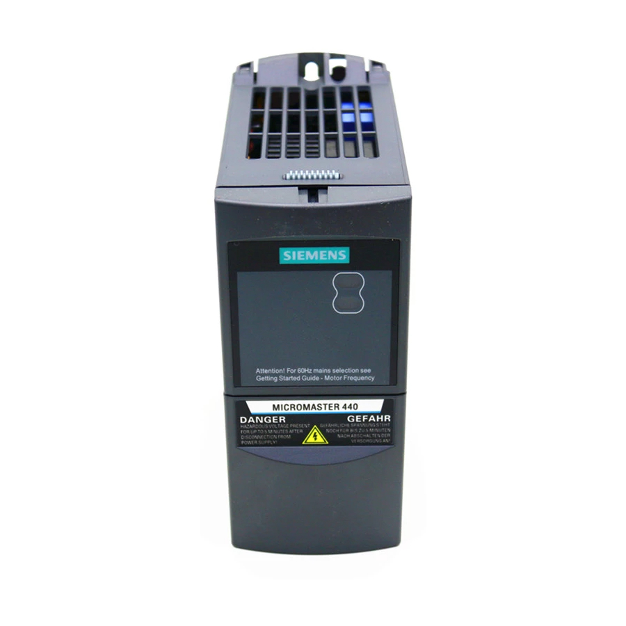
- Page 1 MICROMASTER 440 Parameter List Issue 01/06 User Documentation 6SE6400-5BB00-0BP0...
- Page 2 Available Documentation for the MICROMASTER 440 Getting Started Guide Is for quick commissioning with SDP and BOP. Operating Instructions Gives information about features of the MICROMASTER 440, Installation, Commissioning, Control modes, System Parameter structure, Troubleshooting, Specifications and available options of the MICROMASTER 440.
- Page 3 Block Diagram and Terminals Parameter List MICROMASTER 440 Function Diagrams Parameter List User Documentation Faults and Alarms Abbreviations Valid for Issue 01/06 Converter Type Software Version MICROMASTER 440 V2.1 Issue 01/06...
- Page 4 Please refer to all Definitions and Warnings contained in the Operating Instructions. You will find the Operating Instructions on the Docu CD delivered with your inverter. If the CD is lost, it can be ordered via your local Siemens department under the Order No. 6SE6400-5AD00-1AP0.
-
Page 5: Table Of Contents
Table of Contents Parameters MICROMASTER 440 This Parameter List must only be used together with the Operating Instructions of the MICROMASTER 440. Please pay special attention to the Warnings, Cautions, Notices and Notes contained in these manuals. Table of Contents Block Diagram and Terminals ..............7... -
Page 6: Table Of Contents
Positioning down ramp ................239 3.39 Free function blocks (FFB) ..............241 3.40 Inverter parameters ................257 Function Diagrams ................259 Faults and Alarms ................. 307 Fault messages ..................307 Alarm Messages..................315 Abbreviations..................321 MICROMASTER 440 Parameter List 6SE6400-5BB00-0BP0... -
Page 7: Block Diagram And Terminals
30 V DC / 5 A (resistive) Relay2 250 V AC / 2 A (inductive) 0 - 20 mA DIP switch current (on I/O Board) 0 - 10 V voltage Relay3 COM link RS485 U,V,W automatic Option MICROMASTER 440 Parameter List 6SE6400-5BB00-0BP0... -
Page 8: Power Terminals
Block Diagram and Terminals Issue 01/06 Power Terminals You can gain access to the mains and motor terminals by removing the front covers. Fig. 1-1 Frame Size A - F MICROMASTER 440 Parameter List 6SE6400-5BB00-0BP0... - Page 9 Status Display Panel Elektronic box Bottom adjustment rail Bottom retaining screw Fan screws Shield connection control leads Fan fuses Transformer adaption Motor cable Phase U2, V2, W2 Motor cable PE Shield connection Fig. 1-2 Frame Size FX MICROMASTER 440 Parameter List 6SE6400-5BB00-0BP0...
- Page 10 Status Display Panel Elektronic box Bottom adjustment rail Bottom retaining screw Fan screws Shield connection control leads Fan fuses Transformer adaption Motor cable Phase U2, V2, W2 Motor cable PE Shield connection Fig. 1-3 Frame Size GX MICROMASTER 440 Parameter List 6SE6400-5BB00-0BP0...
-
Page 11: Control Terminals
Digital output 3 / Changeover contact DAC2+ Analog output 2 (+) DAC2- Analog output 2 (-) Isolated output 0 V / max. 100 mA RS485 port RS485 port Fig. 1-4 Control terminals of MICROMASTER 440 MICROMASTER 440 Parameter List 6SE6400-5BB00-0BP0... -
Page 12: Parameters
2 settings. The BiCo system allows complex functions to be programmed. Boolean and mathematical relationships can be set up between inputs (digital, analog, serial etc.) and outputs (inverter current, frequency, analog output, relays, etc.). MICROMASTER 440 Parameter List 6SE6400-5BB00-0BP0... - Page 13 Indicates the level of user access. There are four access levels: Standard, Extended, Expert and Service. The number of parameters that appear in each functional group depends on the access level set in P0003 (user access level). MICROMASTER 440 Parameter List 6SE6400-5BB00-0BP0...
- Page 14 Comparison operators > Greater than >= Greater than / equal to < Less than <= Less than / equal to Equivalence operators Equal to Not equal to Logical operators && AND logic operation OR logic operation MICROMASTER 440 Parameter List 6SE6400-5BB00-0BP0...
- Page 15 To reset all parameters to the factory default settings; the following parameters should be set as follows: Set P0010 = 30 Set P0970 = 1 Note The reset process takes approximately 10 seconds to complete. Reset to Factory default MICROMASTER 440 Parameter List 6SE6400-5BB00-0BP0...
- Page 16 Seven-segment display The seven-segment display is structured as follows: Segment Bit 15 14 13 12 Segment Bit The significance of the relevant bits in the display is described in the status and control word parameters. MICROMASTER 440 Parameter List 6SE6400-5BB00-0BP0...
-
Page 17: Command And Drive Datasets - Overview
CI: PID feedback P1071[3] CI: Main setpoint scaling 1) X = Parameters will be altered during data set switchover (CDS) in the state "Run" – = Parameters will be altered in the state "Ready" only MICROMASTER 440 Parameter List 6SE6400-5BB00-0BP0... - Page 18 Magnetizing curve imag 1 P1009[3] Fixed frequency 9 P0367[3] Magnetizing curve imag 2 P1010[3] Fixed frequency 10 P0368[3] Magnetizing curve imag 3 P1011[3] Fixed frequency 11 P0369[3] Magnetizing curve imag 4 P1012[3] Fixed frequency 12 MICROMASTER 440 Parameter List 6SE6400-5BB00-0BP0...
- Page 19 P1251[3] Integration time Vdc-controller P1530[3] Motoring power limitation P1252[3] Differential time Vdc-controller P1531[3] Regenerative power limitation P1253[3] Vdc-controller output limitation P1570[3] CO: Fixed value flux setpoint P1256[3] Reaction of kinetic buffering P1574[3] Dynamic voltage headroom MICROMASTER 440 Parameter List 6SE6400-5BB00-0BP0...
- Page 20 Delay time permitted deviation P2484[3] No. of shaft turns = 1 Unit P2487[3] Positional error trim value P2166[3] Delay time ramp up completed P2488[3] Distance / No. of revolutions P2167[3] Switch-off frequency f_off P2168[3] Delay time T_off MICROMASTER 440 Parameter List 6SE6400-5BB00-0BP0...
-
Page 21: Binector Input Parameters
BI: Timer 1 P1141[3] BI: RFG start P2854 BI: Timer 2 P1142[3] BI: RFG enable setpoint P2859 BI: Timer 3 P1230[3] BI: Enable DC braking P2864 BI: Timer 4 P1477[3] BI: Set integrator of n-ctrl. MICROMASTER 440 Parameter List 6SE6400-5BB00-0BP0... -
Page 22: Connector Input Parameters
BO: XOR 3 r2867 BO: Timer 4 r2829 BO: NOT 1 r2868 BO: Nout timer 4 r2831 BO: NOT 2 r2886 BO: CMP 1 r2833 BO: NOT 3 r2888 BO: CMP 2 r2835 BO: Q D-FF 1 MICROMASTER 440 Parameter List 6SE6400-5BB00-0BP0... -
Page 23: Connector Output Parameters
CO: Upper torque limit (total) r0086 CO: Act. active current r1539 CO: Lower torque limit (total) r0090 CO: Act. rotor angle P1570[3] CO: Fixed value flux setpoint r0394 CO: Stator resistance IGBT [%] r1583 CO: Flux setpoint (smoothed) MICROMASTER 440 Parameter List 6SE6400-5BB00-0BP0... -
Page 24: Connector/Binector Output Parameters
CO/BO: Act. control word 1 r0747 CO/BO: State of digital outputs r0055 CO/BO: Act. control word 2 r0785 CO/BO: Zustand Analogausgang r1407 CO/BO: Status 2 of motor control r2197 CO/BO: Monitoring word 1 r2198 CO/BO: Monitoring word 2 MICROMASTER 440 Parameter List 6SE6400-5BB00-0BP0... -
Page 25: Parameter Description
Commands, binary I/O ADC and DAC Setpoint channel / RFG Drive features Motor control Communication Alarms / warnings / monitoring Technology controller (e.g. PID) Example: P0004 = 22 specifies that only PID parameters will be visible. MICROMASTER 440 Parameter List 6SE6400-5BB00-0BP0... - Page 26 Defines time period after which the backlight display turns off if no operator keys have been pressed. Value: P0007 = 0: Backlight always on (default state). P0007 = 1 - 2000: Number of seconds after which the backlight will turn off. MICROMASTER 440 Parameter List 6SE6400-5BB00-0BP0...
- Page 27 P0013 index 19 = 12 (key for user defined parameter) P0013 index 18 = 10 (commissioning parameter filter) P0013 index 17 = 3 (user access level) 4. Set P0003 = 0 to activate the user defined parameter. MICROMASTER 440 Parameter List 6SE6400-5BB00-0BP0...
- Page 28 6. If "Store request via USS/CB" and P0014[x] are not consistent, the setting of P14[x] = "store nonvolatile (EEPROM)" has always higher priority. Store request via USS /CB Value of P 0014[x] Result EEPROM EEPROM EEPROM EEPROM EEPROM EEPROM EEPROM MICROMASTER 440 Parameter List 6SE6400-5BB00-0BP0...
-
Page 29: Diagnosis Parameters
Def: P-Group: CONTROL Max: Displays calculated rotor speed based on inverter output frequency [Hz] x 120 / number of poles. ⋅ r0022 [1/min] r0021 [Hz] r0313 Note: This calculation makes no allowance for load-dependent slip. MICROMASTER 440 Parameter List 6SE6400-5BB00-0BP0... - Page 30 Note: For asynchronous motors, a limit is calculated for the torque generating current component (in conjunction with the maximum possible output voltage (r0071), motor leakage and current field weakening (r0377)) and this prevents motor stalling. MICROMASTER 440 Parameter List 6SE6400-5BB00-0BP0...
- Page 31 Min: Datatype: Float Unit: °C Def: P-Group: MOTOR Max: Displays measured motor temperature. Index: r0035[0] : 1st. Drive data set (DDS) r0035[1] : 2nd. Drive data set (DDS) r0035[2] : 3rd. Drive data set (DDS) MICROMASTER 440 Parameter List 6SE6400-5BB00-0BP0...
- Page 32 Displays electrical energy used by inverter since display was last reset (see P0040 - reset energy consumption meter). ac t ⋅ ⋅ ⋅ ⋅ ⋅ ϕ r0039 ∫ ∫ Dependency: Value is reset when P0040 = 1 (reset energy consumption meter). MICROMASTER 440 Parameter List 6SE6400-5BB00-0BP0...
- Page 33 Displays currently selected and active drive data set (DDS). Possible Settings: 1st. Drive data set (DDS) 2nd. Drive data set (DDS) 3rd. Drive data set (DDS) Index: r0051[0] : Selected drive data set r0051[1] : Active drive data set Details: See parameter P0820. MICROMASTER 440 Parameter List 6SE6400-5BB00-0BP0...
- Page 34 Output of Bit3 (Fault) will be inverted on digital output (Low = Fault, High = No Fault). r0052 Bit08 "Deviation setpoint / act. value" ==> see parameter P2164 r0052 Bit10 "f_act >= P1082 (f_max)" ==> see parameter P1082 r0052 Bit12 "Motor holding brake active" ==> see parameter P1215 MICROMASTER 440 Parameter List 6SE6400-5BB00-0BP0...
- Page 35 Bit03 ==> see parameter P2170 r0053 Bit04 ==> see parameter P2155 r0053 Bit05 ==> see parameter P2155 r0053 Bit06 ==> see parameter P2150 r0053 Bit07 ==> see parameter P2172 r0053 Bit08 ==> see parameter P2172 MICROMASTER 440 Parameter List 6SE6400-5BB00-0BP0...
- Page 36 DC brake enabled Bit11 Droop enabled Bit12 Torque control Bit13 External fault 1 Bit15 Command data set (CDS) Bit 1 Details: See description of seven-segment display given in the "Introduction to MICROMASTER System Parameters" in this handbook. MICROMASTER 440 Parameter List 6SE6400-5BB00-0BP0...
- Page 37 160 ms Act. filtered frequency P1300 r0021 Act. frequency SLVC <20 (Observer r0063 20,22 model) 21,23 P0400 r0313 ⋅ P0408 Act. encoder frequency r0061 Encoder 1, 2 P1300 = 21,23 and P0400 = 0 --> F0090 MICROMASTER 440 Parameter List 6SE6400-5BB00-0BP0...
- Page 38 Level Min: Datatype: Float Unit: A Def: P-Group: CONTROL Max: Displays phase currents. Index: r0069[0] : U_phase r0069[1] : V_phase r0069[2] : W_phase r0069[3] : Offset U_phase r0069[4] : Offset V_phase r0069[5] : Offset W_phase MICROMASTER 440 Parameter List 6SE6400-5BB00-0BP0...
- Page 39 Unit: % Def: P-Group: CONTROL Max: Displays actual modulation index. The modulation index is defined as ratio between the magnitude of the fundamental component in the inverter phase output voltage and half of the dc-link voltage. MICROMASTER 440 Parameter List 6SE6400-5BB00-0BP0...
- Page 40 Applies when V/f control is selected in P1300 (control mode); otherwise, the display shows the value zero. r0090 CO: Act. rotor angle Level Min: Datatype: Float Unit: ° Def: P-Group: CONTROL Max: Indicates the current angle of the rotor. This function is not available on single input channel encoders. MICROMASTER 440 Parameter List 6SE6400-5BB00-0BP0...
- Page 41 5th PZD signal r0096[5] : 6th PZD signal r0096[6] : 7th PZD signal r0096[7] : 8th PZD signal r0096[8] : 9th PZD signal r0096[9] : 10th PZD signal Note: r0096 = 100 % corresponds to 4000 hex. MICROMASTER 440 Parameter List 6SE6400-5BB00-0BP0...
-
Page 42: Inverter Parameters (Hw)
P0100 setting 2 (==> [kW], frequency default 60 [Hz]) is not overwritten by the setting of DIP switch 2 (see diagram above). P0199 Equipment system number Level Min: CStat: Datatype: U16 Unit: - Def: P-Group: - Active: first confirm QuickComm.: No Max: Equipment system number This parameter has no operation effect. MICROMASTER 440 Parameter List 6SE6400-5BB00-0BP0... - Page 43 3A C380-480V +10% -10% 47-63Hz 4 Cl. A 91 6SE6440-2UD25-5CA x 3A C380-480V +10% -10% 47-63Hz 7,5 no 92 6SE6440-2UD27-5CA x 3A C380-480V +10% -10% 47-63Hz 11 no 93 6SE6440-2UD31-1CA x 3A C380-480V +10% -10% 47-63Hz 15 no MICROMASTER 440 Parameter List 6SE6400-5BB00-0BP0...
- Page 44 Act. inverter type Min: Datatype: U16 Unit: - Def: P-Group: INVERTER Max: Type number of actual inverter identified. Possible Settings: MICROMASTER 420 MICROMASTER 440 MICRO- / COMBIMASTER 411 MICROMASTER 410 Reserved MICROMASTER 440 PX MICROMASTER 430 MICROMASTER 440 Parameter List 6SE6400-5BB00-0BP0...
- Page 45 P ~ f P ~ f Characteristic Calenders with Application Winders Hoisting gear Pumps viscous friction Facing lathes Belt conveyors Fans Eddy-current brakes Rotary cutting Process machines Centrifuges machines Involving forming Rolling mills Planers Compressors MICROMASTER 440 Parameter List 6SE6400-5BB00-0BP0...
- Page 46 The different values can be taken from the appropriate Catalog or are saved in the drive inverter (refer to Fig.). The VT rated current r0207[1] or CT rated current r0207[2] represent the matching 4-pole Siemens IEC standard motor for the selected load duty cycle (refer to the diagram). Parameters r0207[1] or r0207[2] are used as default values for P0305 as a function of the CT/VT application (load duty cycle).
- Page 47 : Max. allowed unscreened cable length r0231[1] : Max. allowed screened cable length Notice: For full EMC compliance, the screened cable must not exceed 25 m in length when an EMC filter is fitted. MICROMASTER 440 Parameter List 6SE6400-5BB00-0BP0...
- Page 48 Bit01 Reserved Bit02 Phase loss detection enable Index: P0291[0] : 1st. Drive data set (DDS) P0291[1] : 2nd. Drive data set (DDS) P0291[2] : 3rd. Drive data set (DDS) Details: See P0290 (inverter overload reaction) MICROMASTER 440 Parameter List 6SE6400-5BB00-0BP0...
- Page 49 Active: first confirm QuickComm.: No Max: 3600 Defines inverter fan switch off delay time in seconds after drive has stopped. Note: Setting to 0, inverter fan will switch off when the drive stops, that is no delay. MICROMASTER 440 Parameter List 6SE6400-5BB00-0BP0...
-
Page 50: Motor Parameters
P1335 Slip compensation P1336 Slip limit P0320 Motor magnetizing current P0330 Rated motor slip P0331 Rated magnetization current P0332 Rated power factor P0384 Rotor time constant P1200, P1202, P1203 Flying start P1230, P1232, P1233 DC braking MICROMASTER 440 Parameter List 6SE6400-5BB00-0BP0... - Page 51 MICROMASTER 410 MICROMASTER 411 MICROMASTER 420 MICROMASTER 430 MICROMASTER 440 *) Line supply voltage 1-ph. 110 V AC is stepped-up --> frequency inverter output voltage 3-ph. 230 V AC Index: P0304[0] : 1st. Drive data set (DDS) P0304[1] : 2nd. Drive data set (DDS) P0304[2] : 3rd.
- Page 52 Dependency: If P0100 = 1, values will be in [hp] - see diagram P0304 (rating plate). Changeable only when P0010 = 1 (quick commissioning). Default value is depending on inverter type and its rating data. MICROMASTER 440 Parameter List 6SE6400-5BB00-0BP0...
- Page 53 Pole pair number recalculated automatically if parameter is changed. Default value is depending on inverter type and its rating data. Required for vector control and V/f control with speed controller. Details: See diagram in P0304 (rating plate) MICROMASTER 440 Parameter List 6SE6400-5BB00-0BP0...
- Page 54 Unit: A Def: P-Group: MOTOR Max: Displays calculated magnetizing current of motor in [A]. Index: r0331[0] : 1st. Drive data set (DDS) r0331[1] : 2nd. Drive data set (DDS) r0331[2] : 3rd. Drive data set (DDS) MICROMASTER 440 Parameter List 6SE6400-5BB00-0BP0...
- Page 55 Applications with variable torque the reduction of max. current leeds automatically to a reduction of the load / output current. Notice: Motors of series 1LA1 and 1LA8 have an internal fan. This internal motor fan must not be confused with the fan at the end of the motor shaft. MICROMASTER 440 Parameter List 6SE6400-5BB00-0BP0...
- Page 56 (P0344, P0341, P0342). P0340 = 4: The vector control parameters are pre-assigned starting from the motor equivalent circuit diagram parameters (ESB, P0350 - P0369) and motor weight/moment of inertia, moment of inertia ratio (P0344, P0341, P0342). MICROMASTER 440 Parameter List 6SE6400-5BB00-0BP0...
- Page 57 P2003[3] Reference torque P2174[3] Torque threshold M_thresh P2185[3] Upper torque threshold 1 P2186[3] Lower torque threshold 1 P2187[3] Upper torque threshold 2 P2188[3] Lower torque threshold 2 P2189[3] Upper torque threshold 3 P2190[3] Lower torque threshold 3 MICROMASTER 440 Parameter List 6SE6400-5BB00-0BP0...
- Page 58 If boost settings are higher than 100 %, magnetization time may be reduced. Default value is depending on inverter type and its rating data. An excessive reduction of this time can result in insufficient motor magnetization. MICROMASTER 440 Parameter List 6SE6400-5BB00-0BP0...
- Page 59 Since measured line-to-line, this value may appear to be higher (up to 2 times higher) than expected. The value entered in P0350 (stator resistance) is the one obtained by the method last used. Default value is depending on inverter type and its rating data. MICROMASTER 440 Parameter List 6SE6400-5BB00-0BP0...
- Page 60 Index: P0358[0] : 1st. Drive data set (DDS) P0358[1] : 2nd. Drive data set (DDS) P0358[2] : 3rd. Drive data set (DDS) Dependency: Calculated automatically using the motor model or determined using P1910 (motor identification). MICROMASTER 440 Parameter List 6SE6400-5BB00-0BP0...
- Page 61 Invers - Γ Γ Γ Γ - equivalent circuit : Cable res. [%] Stator res. [%] Tot.leak.react. [%] Rotor res. [%] r0372.D r0370.D r0377.D r0374.D RΓ (r0331) σ RΓ Cable µΓ Main reactance [%] mΓ r0382.D Cable MICROMASTER 440 Parameter List 6SE6400-5BB00-0BP0...
- Page 62 Specifies second flux value of saturation characteristic in [%] relative to rated motor voltage (P0304). Index: P0363[0] : 1st. Drive data set (DDS) P0363[1] : 2nd. Drive data set (DDS) P0363[2] : 3rd. Drive data set (DDS) Details: See P0362 (magnetizing curve flux 1). MICROMASTER 440 Parameter List 6SE6400-5BB00-0BP0...
- Page 63 Index: P0368[0] : 1st. Drive data set (DDS) P0368[1] : 2nd. Drive data set (DDS) P0368[2] : 3rd. Drive data set (DDS) Dependency: Affects P0320 (motor magnetizing current). Details: See P0362 (magnetizing curve flux 1). MICROMASTER 440 Parameter List 6SE6400-5BB00-0BP0...
- Page 64 : 2nd. Drive data set (DDS) r0373[2] : 3rd. Drive data set (DDS) Note: ambient temperature, refer to P0625 temperature rise of the stator winding, refer to P0627 Rated motor impedance: 0304 <=> ⋅ ⋅ 0305 MICROMASTER 440 Parameter List 6SE6400-5BB00-0BP0...
- Page 65 ⋅ (P0360 P0358) σ Index: r0382[0] : 1st. Drive data set (DDS) r0382[1] : 2nd. Drive data set (DDS) r0382[2] : 3rd. Drive data set (DDS) Note: Rated motor impedance: 0304 <=> ⋅ ⋅ 0305 MICROMASTER 440 Parameter List 6SE6400-5BB00-0BP0...
- Page 66 Note: Actual rotor winding temperature, refer to r0633 Values greater than 25 % tend to produce excessive motor slip. Check rated motor speed [rpm] value (P0311). Rated motor impedance: 0304 <=> ⋅ ⋅ 0305 MICROMASTER 440 Parameter List 6SE6400-5BB00-0BP0...
-
Page 67: Speed Encoder
Encoders with zero pulse can also be connected, but the zero pulse is not used in MM4. The term "quadrature" in setting 2 refers to two periodic functions separated by a quarter cycle or 90 degrees. MICROMASTER 440 Parameter List 6SE6400-5BB00-0BP0... - Page 68 When allowed frequency difference is set to 0, both the high frequency and low frequency encoder loss detection is disabled, thus encoder loss will not be detected. If encoder loss detection is disabled and encoder loss occurs, then operation of the motor may become unstable. MICROMASTER 440 Parameter List 6SE6400-5BB00-0BP0...
-
Page 69: Application Macros
Using a PTC sensor the temperature of the motor is calculated by the sensor in conjunction with the thermal model. This allows for redundancy of the monitoring process. MICROMASTER 440 Parameter List 6SE6400-5BB00-0BP0... - Page 70 The data, required for the thermal motor model, is estimated from the rating plate data entered during the quick commissioning. This data permits reliable, stable operation for standard Siemens motors. If required, parameter changes must be made for motors from third-party manufacturers. We always recommend that an automatic motor data identification run is made after quick commissioning so that the electrical equivalent circuit diagram data can be determined.
- Page 71 Clearly a motor running with a high current (maybe due to boost) and a low speed, will overheat more quickly than one running at 50 or 60 Hz, full load. The MM4 take account of these factors. MICROMASTER 440 Parameter List 6SE6400-5BB00-0BP0...
- Page 72 Active: Immediately QuickComm.: No Max: 200.0 Overtemperature of stator iron. Index: P0626[0] : 1st. Drive data set (DDS) P0626[1] : 2nd. Drive data set (DDS) P0626[2] : 3rd. Drive data set (DDS) Note: See parameter P0627 MICROMASTER 440 Parameter List 6SE6400-5BB00-0BP0...
- Page 73 Unit: °C Def: P-Group: MOTOR Max: Displays stator winding temperature of motor mass model. Index: r0632[0] : 1st. Drive data set (DDS) r0632[1] : 2nd. Drive data set (DDS) r0632[2] : 3rd. Drive data set (DDS) MICROMASTER 440 Parameter List 6SE6400-5BB00-0BP0...
- Page 74 P0640[2] : 3rd. Drive data set (DDS) Dependency: Limited to maximum inverter current or to 400 % of rated motor current (P0305), whichever is the lower. ⋅ (r0209, P0305) ⋅ P0640 P0305 Details: See function diagram for current limitation. MICROMASTER 440 Parameter List 6SE6400-5BB00-0BP0...
-
Page 75: Command Source
P0700 = 2 P0700 = 4 P0700 = 5 P0700 = 6 P0701 P0702 P0703 P0704 P0705 P0706 P0707 P0708 P0731 52.3 52.3 52.3 52.3 52.3 52.3 P0732 52.7 52.7 52.7 52.7 52.7 52.7 P0733 P0800 P0801 MICROMASTER 440 Parameter List 6SE6400-5BB00-0BP0... - Page 76 The following parameters are not overwritten when changing P 0700: P0810 P0811 P0820 P0821 P2810 P2812 P2814 P2816 P2818 P2820 P2822 P2824 P2826 P2828 P2830 P2832 P2834 P2837 P2840 P2843 P2846 P2849 P2854 P2859 P2864 MICROMASTER 440 Parameter List 6SE6400-5BB00-0BP0...
-
Page 77: Digital Inputs
P0700 command source or P0010 = 1, P3900 = 1, 2 or 3 quick commissioning or P0010 = 30, P0970 = 1 factory reset in order to reset. Notice: Setting 99 (BICO) for expert use only. MICROMASTER 440 Parameter List 6SE6400-5BB00-0BP0... - Page 78 Disable additional freq setpoint Enable BICO parameterization Index: P0703[0] : 1st. Command data set (CDS) P0703[1] : 2nd. Command data set (CDS) P0703[2] : 3rd. Command data set (CDS) Details: See P0701 (function of digital input 1). MICROMASTER 440 Parameter List 6SE6400-5BB00-0BP0...
- Page 79 Disable additional freq setpoint Enable BICO parameterization Index: P0705[0] : 1st. Command data set (CDS) P0705[1] : 2nd. Command data set (CDS) P0705[2] : 3rd. Command data set (CDS) Details: See P0701 (function of digital input 1). MICROMASTER 440 Parameter List 6SE6400-5BB00-0BP0...
- Page 80 P0707[1] : 2nd. Command data set (CDS) P0707[2] : 3rd. Command data set (CDS) Note: Signals above 4 V are active, signals below 1,6 V are inactive. Details: See P0701 (function of digital input 1). MICROMASTER 440 Parameter List 6SE6400-5BB00-0BP0...
- Page 81 Cmd = CB on COM link Setpoint = USS on BOP link Cmd = CB on COM link Setpoint = CB on COM link Cmd = CB on COM link Setpoint = Analog 2 setp MICROMASTER 440 Parameter List 6SE6400-5BB00-0BP0...
- Page 82 Digital input 3 Bit03 Digital input 4 Bit04 Digital input 5 Bit05 Digital input 6 Bit06 Digital input 7 (via ADC 1) Bit07 Digital input 8 (via ADC 2) Note: Segment is lit when signal is active. MICROMASTER 440 Parameter List 6SE6400-5BB00-0BP0...
- Page 83 Possible Settings: NPN mode ==> low active PNP mode ==> high active Value: NPN: Terminals 5/6/7/8/16/17 must be connected via terminal 28 ( O V). PNP: Terminals 5/6/7/8/16/17 must be connected via terminal 9 (24 V). MICROMASTER 440 Parameter List 6SE6400-5BB00-0BP0...
-
Page 84: Digital Outputs
PID output r2294 == P2292 (PID_min) 0 Closed 53.B PID output r2294 == P2291 (PID_max) 0 Closed Details: Display functions ==> see parameter r0052, r0053 Motor holding brake ==> see parameter P1215 DC brake ==> see parameter P1232, P1233 MICROMASTER 440 Parameter List 6SE6400-5BB00-0BP0... - Page 85 0 Closed 53.7 Act. Vdc r0026 < P2172 0 Closed 53.8 Act. Vdc r0026 > P2172 0 Closed 53.A PID output r2294 == P2292 (PID_min) 0 Closed 53.B PID output r2294 == P2291 (PID_max) 0 Closed MICROMASTER 440 Parameter List 6SE6400-5BB00-0BP0...
-
Page 86: Analog Inputs
Wire breakage / signal loss F0080 is detected if the ADC input quantity is less than 0.5 * P0761. Analog input P0761 0,5 ⋅ P0761 Signal loss r0751 Fault acknowl. P0762 F0080 Act. ADC after scaling r0755 MICROMASTER 440 Parameter List 6SE6400-5BB00-0BP0... - Page 87 Max: Shows smoothed value of analog input in [%] after scaling block. Index: r0754[0] : Analog input 1 (ADC 1) r0754[1] : Analog input 2 (ADC 2) Dependency: P0757 to P0760 define range (ADC scaling). MICROMASTER 440 Parameter List 6SE6400-5BB00-0BP0...
- Page 88 OFF = voltage input (10 V) ON = current input (20 mA) Allocation of DIPs to analog inputs is as follows: DIP on left (DIP 1) = Analog input 1 DIP on right (DIP 2) = Analog input 2 MICROMASTER 440 Parameter List 6SE6400-5BB00-0BP0...
- Page 89 ASPmin represents lowest analog setpoint (this may be at 0 V or 20 mA). Default values provide a scaling of 0 V or 0 mA = 0 %, and 10 V or 20 mA = 100 %. MICROMASTER 440 Parameter List...
- Page 90 Sets value of Y1 in [%] as described in P0757 (ADC scaling) Index: P0758[0] : Analog input 1 (ADC 1) P0758[1] : Analog input 2 (ADC 2) Dependency: Affects P2000 to P2003 (reference frequency, voltage, current or torque) depending on which setpoint is to be generated. MICROMASTER 440 Parameter List 6SE6400-5BB00-0BP0...
- Page 91 0.2 V wide (0.1 V to each side of center, ADC value 0 to 10 V, -50 to +50 Hz): P2000 = 50 Hz P0759 = 8 V P0760 = 75 % P0757 = 2 V P0758 = -75 % P0761 = 0.1 V P0756 = 0 or 1 MICROMASTER 440 Parameter List 6SE6400-5BB00-0BP0...
- Page 92 Defines time delay between loss of analog setpoint and appearance of fault code F0080. Index: P0762[0] : Analog input 1 (ADC 1) P0762[1] : Analog input 2 (ADC 2) Note: Expert users can choose the desired reaction to F0080 (default is OFF2). MICROMASTER 440 Parameter List 6SE6400-5BB00-0BP0...
-
Page 93: Analog Outputs
If the value was originally negative then the corresponding bit in R0783 is set, otherwise it is cleared. Possible Settings: Index: P0775[0] : Analog output 1 (DAC 1) P0775[1] : Analog output 2 (DAC 2) MICROMASTER 440 Parameter List 6SE6400-5BB00-0BP0... - Page 94 The default values of the scaling block provides a scaling of: P1: 0.0 % = 0 mA P2: 100.0 % = 20 mA Dependency: Affects P2000 to P2003 (referency frequency, voltage, current or torque) depending on which setpoint is to be generated. MICROMASTER 440 Parameter List 6SE6400-5BB00-0BP0...
- Page 95 Min: CStat: Datatype: Float Unit: - Def: P-Group: TERMINAL Active: first confirm QuickComm.: No Max: Defines y2 of output characteristic. Index: P0780[0] : Analog output 1 (DAC 1) P0780[1] : Analog output 2 (DAC 2) MICROMASTER 440 Parameter List 6SE6400-5BB00-0BP0...
- Page 96 Displays status of analog output. Bit 0 indicates that the value of analog output 1 is negative. Bit 1 indicates that the value of analog output 2 is negative. Bitfields: Bit00 Analog output 1 -ve Bit01 Analog output 2 -ve MICROMASTER 440 Parameter List 6SE6400-5BB00-0BP0...
-
Page 97: Parameter / Command / Drive Data Set
722.3 = Digital input 4 (requires P0704 to be set to 99, BICO) 722.4 = Digital input 5 (requires P0705 to be set to 99, BICO) 722.5 = Digital input 6 (requires P0706 to be set to 99, BICO) Note: See parameter P0800 MICROMASTER 440 Parameter List 6SE6400-5BB00-0BP0... - Page 98 CO/BO: Act CtrlWd2 P0811 r0055 (0:0) r0055 CO/BO: Act BI: CDS b0 loc/rem CtrlWd1 P0810 r0054 (0:0) r0054 Changeover Changeover approx. approx. time time CDS active 4 ms 4 ms r0050 CO: Active CDS r0050 MICROMASTER 440 Parameter List 6SE6400-5BB00-0BP0...
- Page 99 722.6 = Digital input 7 (via analog input 1, requires P0707 to be set to 99) 722.7 = Digital input 8 (via analog input 2, requires P0708 to be set to 99) Note: P0810 is also relevant for command data set (CDS) selection. MICROMASTER 440 Parameter List 6SE6400-5BB00-0BP0...
- Page 100 CO/BO: Act CtrlWd2 P0821 r0055 (0:0) r0055 BI: DDS bit 0 CO/BO: Act CtrlWd2 P0820 r0055 (0:0) r0055 Changeover time Changeover time approx. 50 ms approx. 50 ms DDS active r0051[1] CO: Active DDS r0051 [2] MICROMASTER 440 Parameter List 6SE6400-5BB00-0BP0...
- Page 101 Connect P0820 (P0821 if necessary) with DDS source (i.e. via DIN 4: P0704[0] = 99, P0820 = 722.3) Switch-over to DDS2 (check it via r0051) Commission Motor 2; Adapt all other DDS2 parameters (as required) Motor 1 Motor 2 Note: P0821 is also relevant for drive data set (DDS) selection. MICROMASTER 440 Parameter List 6SE6400-5BB00-0BP0...
-
Page 102: Bico Command Parameters
Active only when P0719 < 10. See parameter P0719 (Selection of command/setpoint source). Note: OFF1 means a ramp stop down to 0 using P1121. OFF1 is low active. For the priority of all soft commands, the following applies: OFF2, OFF3, OFF1 MICROMASTER 440 Parameter List 6SE6400-5BB00-0BP0... - Page 103 Active only when P0719 < 10. See parameter P0719 (Selection of command/setpoint source). Note: OFF2 means an immediate pulse inhibit; the motor coasts down. OFF2 is low active. The following applies for the priority of all of the OFF commands: OFF2, OFF3, OFF1 MICROMASTER 440 Parameter List 6SE6400-5BB00-0BP0...
- Page 104 Dependency: Active only when P0719 < 10. See parameter P0719 (Selection of command/setpoint source). Note: OFF3 means fast ramp-down to 0 Hz through P1135. OFF3 is low-active. Priority of all OFF commands: OFF2, OFF3, OFF1 MICROMASTER 440 Parameter List 6SE6400-5BB00-0BP0...
-
Page 105: Communication Parameters
The following applies when a PROFIBUS module is used: DIP switch = 0 Address defined in P0918 (CB address) is valid DIP switch not = 0 DIP switch setting has priority and P0918 indicates DIP switch setting. MICROMASTER 440 Parameter List 6SE6400-5BB00-0BP0... - Page 106 Whenever a fault in index 0 is acknowledged (F1e), the fault history shifts as indicated in the diagram above. Dependency: Index 1 used only if second fault occurs before first fault is acknowledged. Details: See "Faults and Warnings" MICROMASTER 440 Parameter List 6SE6400-5BB00-0BP0...
- Page 107 : Recent fault trip -2, fault value 5 r0949[5] : Recent fault trip -2, fault value 6 r0949[6] : Recent fault trip -3, fault value 7 r0949[7] : Recent fault trip -3, fault value 8 MICROMASTER 440 Parameter List 6SE6400-5BB00-0BP0...
- Page 108 Datatype: U16 Unit: - Def: P-Group: COMM Max: Firmware version data. Index: r0964[0] : Company (Siemens = 42) r0964[1] : Product type r0964[2] : Firmware version r0964[3] : Firmware date (year) r0964[4] : Firmware date (day/month) Example: Value Meaning r0964[0]...
- Page 109 Drivemonitor is displayed "NC" (not connected) in the status line or "drive busy". BOP displays "busy" After completion of the transfer process, the communication between the inverter and the PC-tools (e.g. Starter) or BOP is automatically re-established. MICROMASTER 440 Parameter List 6SE6400-5BB00-0BP0...
-
Page 110: Setpoint Source
+ Analog setpoint 2 USS on BOP link + Analog setpoint 2 USS on COM link + Analog setpoint 2 CB on COM link + Analog setpoint 2 Analog setpoint 2 + Analog setpoint 2 MICROMASTER 440 Parameter List 6SE6400-5BB00-0BP0... - Page 111 Be aware, by changing of parameter P1000 all BICO parameters (see table below) are modified. Note: Single digits denote main setpoints that have no additional setpoint. Changing this parameter sets (to default) all settings on item selected (see table). MICROMASTER 440 Parameter List 6SE6400-5BB00-0BP0...
- Page 112 755.1 P1070 1.0 P1071 x = 7 755.1 755.1 755.1 755.1 755.1 755.1 755.1 755.1 P1075 1.0 P1076 Example: P1000 = 21 → P1070 = 1050.0 P1071 = 1.0 P1075 = 755.0 P1076 = 1.0 MICROMASTER 440 Parameter List 6SE6400-5BB00-0BP0...
-
Page 113: Fixed Frequencies
P1001[2] : 3rd. Drive data set (DDS) Example: Binary coded selection : DIN4 DIN3 DIN2 DIN1 0 Hz P1001 P1002 P1003 P1004 P1005 P1006 P1007 P1008 P1009 P1010 FF10 P1011 FF11 P1012 FF12 P1013 FF13 P1014 FF14 P1015 FF15 MICROMASTER 440 Parameter List 6SE6400-5BB00-0BP0... - Page 114 650.00 Defines fixed frequency setpoint 5. Index: P1005[0] : 1st. Drive data set (DDS) P1005[1] : 2nd. Drive data set (DDS) P1005[2] : 3rd. Drive data set (DDS) Details: See parameter P1001 (fixed frequency 1). MICROMASTER 440 Parameter List 6SE6400-5BB00-0BP0...
- Page 115 650.00 Defines fixed frequency setpoint 11. Index: P1011[0] : 1st. Drive data set (DDS) P1011[1] : 2nd. Drive data set (DDS) P1011[2] : 3rd. Drive data set (DDS) Details: See parameter P1001 (fixed frequency 1). MICROMASTER 440 Parameter List 6SE6400-5BB00-0BP0...
- Page 116 P1016[0] : 1st. Command data set (CDS) P1016[1] : 2nd. Command data set (CDS) P1016[2] : 3rd. Command data set (CDS) Details: See table in P1001 (fixed frequency 1) for description of how to use fixed frequencies. MICROMASTER 440 Parameter List 6SE6400-5BB00-0BP0...
- Page 117 P1023 = 722.3 ==> Digital input 4 P1026 = 722.4 ==> Digital input 5 P1028 = 722.5 ==> Digital input 6 Dependency: Accessible only if P0701 - P0706 = 99 (function of digital inputs = BICO) MICROMASTER 440 Parameter List 6SE6400-5BB00-0BP0...
- Page 118 P1026[1] : 2nd. Command data set (CDS) P1026[2] : 3rd. Command data set (CDS) Dependency: Accessible only if P0701 - P0706 = 99 (function of digital inputs = BICO). Details: See P1020 (fixed frequency selection Bit 0) for most common settings. MICROMASTER 440 Parameter List 6SE6400-5BB00-0BP0...
- Page 119 P1028[1] : 2nd. Command data set (CDS) P1028[2] : 3rd. Command data set (CDS) Dependency: Accessible only if P0701 - P0706 = 99 (function of digital inputs = BICO). Details: See P1020 (fixed frequency selection Bit 0) for most common settings. MICROMASTER 440 Parameter List 6SE6400-5BB00-0BP0...
-
Page 120: Motorized Potentiometer (Mop)
722.6 = Digital input 7 (via analog input 1, requires P0707 to be set to 99) 722.7 = Digital input 8 (via analog input 2, requires P0708 to be set to 99) 19.E = MOP down via BOP MICROMASTER 440 Parameter List 6SE6400-5BB00-0BP0... - Page 121 Bit13 r2036 Bit14 P0719 = 51 P0719 = 0, P0700 = 6, P1000 = 1 CB control word CB control word P0719 = 1, P0700 = 6 r2090 Bit13 r2090 Bit14 P0719 = 61 MICROMASTER 440 Parameter List 6SE6400-5BB00-0BP0...
- Page 122 722.7 = Digital input 8 (via analog input 2, requires P0708 to be set to 99) 19.9 = JOG left via BOP Dependency: Active only when P0719 < 10. See parameter P0719 (Selection of command/setpoint source). MICROMASTER 440 Parameter List 6SE6400-5BB00-0BP0...
- Page 123 Index: P1059[0] : 1st. Drive data set (DDS) P1059[1] : 2nd. Drive data set (DDS) P1059[2] : 3rd. Drive data set (DDS) Dependency: P1060 and P1061 set up and down ramp times respectively for jogging. MICROMASTER 440 Parameter List 6SE6400-5BB00-0BP0...
- Page 124 Ramp times will be used as follows: P1060 / P1061 : JOG mode is active P1120 / P1121 : Normal mode (ON/OFF) is active P1060 / P1061 : Normal mode (ON/OFF) and P1124 is active MICROMASTER 440 Parameter List 6SE6400-5BB00-0BP0...
-
Page 125: Setpoint Channel
P1075[0] : 1st. Command data set (CDS) P1075[1] : 2nd. Command data set (CDS) P1075[2] : 3rd. Command data set (CDS) Common Settings: = Analog input 1 setpoint 1024 = Fixed frequency setpoint 1050 = Motor potentiometer (MOP) setpoint MICROMASTER 440 Parameter List 6SE6400-5BB00-0BP0... - Page 126 P1055 (BI: Enable JOG right) or P1056 (BI: Enable JOG left) define command source of JOG right or JOG left respectively. Note: P1055 = 0 and P1056 = 0 ==> Total frequency setpoint is selected. MICROMASTER 440 Parameter List 6SE6400-5BB00-0BP0...
- Page 127 |f_act| > f_min P2153 = 0 r0053 Bit 02 Note: Value set here is valid both for clockwise and for anticlockwise rotation. Under certain conditions (e.g. ramping, current limiting), motor can run below minimum frequency. MICROMASTER 440 Parameter List 6SE6400-5BB00-0BP0...
- Page 128 If for example P1082 = 80 Hz, P2000 = 50 Hz and the analog input is parameterised with P0757 = 0 V, P0758 = 0 %, P0759 = 10 V, P0760 = 100 %, a setpoint frequency of 50 Hz will be applied at 10 V of the analog input. MICROMASTER 440 Parameter List 6SE6400-5BB00-0BP0...
- Page 129 Defines skip frequency 3 which avoids effects of mechanical resonance and suppresses frequencies within +/- P1101 (skip frequency bandwidth). Index: P1093[0] : 1st. Drive data set (DDS) P1093[1] : 2nd. Drive data set (DDS) P1093[2] : 3rd. Drive data set (DDS) Details: See P1091 (skip frequency 1). MICROMASTER 440 Parameter List 6SE6400-5BB00-0BP0...
- Page 130 This function does not disable the "reverse command functions" (e.g. Reverse, ON left); rather, a reverse command causes motor to run in the positive direction only, as described above. P1110 = 1 ON/OFF1 Reverse (r1170) P1080 -P1080 (r1078) MICROMASTER 440 Parameter List 6SE6400-5BB00-0BP0...
-
Page 131: Ramp-Function Generator
Ramp times will be used as follows: P1060 / P1061 : JOG mode is active P1120 / P1121 : Normal mode (ON/OFF) is active P1060 / P1061 : Normal mode (ON/OFF) and P1124 is active MICROMASTER 440 Parameter List 6SE6400-5BB00-0BP0... - Page 132 Ramp times will be used as follows: P1060 / P1061 : JOG mode is active P1120 / P1121 : Normal mode (ON/OFF) is active P1060 / P1061 : Normal mode (ON/OFF) and P1124 is active MICROMASTER 440 Parameter List 6SE6400-5BB00-0BP0...
- Page 133 Defines rounding time at start of ramp-down as shown in P1130 (ramp-up initial rounding time). Index: P1132[0] : 1st. Drive data set (DDS) P1132[1] : 2nd. Drive data set (DDS) P1132[2] : 3rd. Drive data set (DDS) Details: See parameter P1130. MICROMASTER 440 Parameter List 6SE6400-5BB00-0BP0...
- Page 134 P1134[0] : 1st. Drive data set (DDS) P1134[1] : 2nd. Drive data set (DDS) P1134[2] : 3rd. Drive data set (DDS) Dependency: No effect until P1132 (Ramp-down initial rounding time) or P1133 (Ramp-down final rounding time) > 0 s. MICROMASTER 440 Parameter List 6SE6400-5BB00-0BP0...
- Page 135 P1142[1] : 2nd. Command data set (CDS) P1142[2] : 3rd. Command data set (CDS) r1170 CO: Frequency setpoint after RFG Level Min: Datatype: Float Unit: Hz Def: P-Group: SETPOINT Max: Displays overall frequency setpoint after ramp generator. MICROMASTER 440 Parameter List 6SE6400-5BB00-0BP0...
-
Page 136: Flying Restart
Settings 4 to 6 search only in direction of setpoint. Flying start must be used in cases where the motor may still be turning (e.g. after a short mains break) or can be driven by the load. Otherwise, overcurrent trips will occur. MICROMASTER 440 Parameter List 6SE6400-5BB00-0BP0... - Page 137 Note: A higher value produces a flatter gradient and thus a longer search time. A lower value has the opposite effect. For closed-loop vector control, parameter P1203 is de-activated MICROMASTER 440 Parameter List 6SE6400-5BB00-0BP0...
- Page 138 RFG hold Bit06 N-adaption set to zero Bit07 Reserved Bit08 Reserved Bit09 Reserved Bit10 Direction Positive Bit11 Search is started Bit12 Current is applied Bit13 Search is aborted Bit14 Deviation is zero Bit15 N-controller is active MICROMASTER 440 Parameter List 6SE6400-5BB00-0BP0...
-
Page 139: Automatic Restart
The inverter will acknowledge the faults (F0003 etc.) at power on after blackout or brownout and restarts the drive. It is necessary that the ON command is wired via digital input (DIN). Setting 6 causes the motor to restart immediately. Following table presents an overview of parameter P1210 and its functionality. MICROMASTER 440 Parameter List 6SE6400-5BB00-0BP0... - Page 140 Number of restart attempts Level Min: CStat: Datatype: U16 Unit: - Def: P-Group: FUNC Active: first confirm QuickComm.: No Max: Specifies number of times inverter will attempt to restart if automatic restart P1210 is activated. MICROMASTER 440 Parameter List 6SE6400-5BB00-0BP0...
-
Page 141: Motor Holding Brake
OFF2 Active OFF1/OFF3 Motor excitation finished r0056 Bit04 p0346 fmin (p1080) p1216 r0052.C Bit 12 open Brake Status closed Brake Release Time Brake Closing Time Possible Settings: Motor holding brake disabled Motor holding brake enabled MICROMASTER 440 Parameter List 6SE6400-5BB00-0BP0... - Page 142 P1080, the motor is held at the minimum frequency for this time. This means that the brake can reliably close before the motor is switched into a no-current condition. P1217 ≥ Application time of the brake + relay closing time Details: See parameter P1215. MICROMASTER 440 Parameter List 6SE6400-5BB00-0BP0...
-
Page 143: Dc Braking
! DC braking is not possible when using a synchronous motor (i.e. P0300 = 2). Notice: This delay time is set in P0347 (demagnetization time). If this delay is too short, overcurrent trips can occur. MICROMASTER 440 Parameter List 6SE6400-5BB00-0BP0... - Page 144 Bit00 P1233 OFF1/OFF3 P0347 OFF2 f OFF ramp OFF2 P1234 DC braking OFF2 DC braking active r0053 Bit00 P1233 The DC current, that is impressed during time P1233, is specified by parameter P1232. MICROMASTER 440 Parameter List 6SE6400-5BB00-0BP0...
- Page 145 DC braking current P1232 for the time duration set in P1233. Index: P1234[0] : 1st. Drive data set (DDS) P1234[1] : 2nd. Drive data set (DDS) P1234[2] : 3rd. Drive data set (DDS) Details: See P1232 (DC braking current) and P1233 (duration of DC braking) MICROMASTER 440 Parameter List 6SE6400-5BB00-0BP0...
-
Page 146: Compound Braking
If used with the Vdc max controller enabled the drive behaviour whilst braking may be worsened paticularly with high values of compound braking. Compound braking does not function when the drive is in vector control. MICROMASTER 440 Parameter List 6SE6400-5BB00-0BP0... -
Page 147: Dynamic Braking
Initially the brake will operate at a high duty cycle dependant on the DC link level until the thermal limit is approached. The duty cycle specified by this parameter will then be imposed. The resistor should be able to operate at this level indefinitely without overheating. Chopper resistor Chopper control MICROMASTER 440 Parameter List 6SE6400-5BB00-0BP0... -
Page 148: Vdc Controller
Vdc-max controller enabled Kinetic buffering (Vdc-min controller) enabled Vdc-max controller and kinetic buffering (KIB) enabled Index: P1240[0] : 1st. Drive data set (DDS) P1240[1] : 2nd. Drive data set (DDS) P1240[2] : 3rd. Drive data set (DDS) MICROMASTER 440 Parameter List 6SE6400-5BB00-0BP0... - Page 149 P1243 = 100 % means parameters P1250, P1251 and P1252 (gain, integration time and differential time) are used as set. Otherwise, these are multiplied by P1243 (dynamic factor of Vdc-max). Note: Vdc controller adjustment is calculated automatically from motor and inverter data. MICROMASTER 440 Parameter List 6SE6400-5BB00-0BP0...
- Page 150 Active: Immediately QuickComm.: No Max: 1000.0 Enters differential time constant for Vdc controller. Index: P1252[0] : 1st. Drive data set (DDS) P1252[1] : 2nd. Drive data set (DDS) P1252[2] : 3rd. Drive data set (DDS) MICROMASTER 440 Parameter List 6SE6400-5BB00-0BP0...
- Page 151 P1256[2] : 3rd. Drive data set (DDS) Note: P1256 = 0: Maintain dclink voltage until mains is returned or drive is tripped undervoltage. The frequency is kept above the frequency limit provided in P1257. P1245 DC_min P1257 Pulse enabled MICROMASTER 440 Parameter List 6SE6400-5BB00-0BP0...
- Page 152 Frequency which kinetic buffering (KIB) either hold speed or disable pulses depending on P1256. Index: P1257[0] : 1st. Drive data set (DDS) P1257[1] : 2nd. Drive data set (DDS) P1257[2] : 3rd. Drive data set (DDS) MICROMASTER 440 Parameter List 6SE6400-5BB00-0BP0...
-
Page 153: Control Mode
User defined characteristic (see P1320) For synchronous motors (e.g. SIEMOSYN motors) P1300 = 5,6 : V/f for textil applications Slip compensation disabled. Imax controller modifies the output voltage only. Imax controller does not influence the output frequency. MICROMASTER 440 Parameter List 6SE6400-5BB00-0BP0... - Page 154 P1470: P gain (SLVC) P1472: I term (SLVC) P1610: Continuous torque boost (SLVC, open loop boost) P1611: Acceleration torque boost (SLVC, open loop boost) P1750: Control word of motor model P1755: Start-frequency motor model (SLVC) MICROMASTER 440 Parameter List 6SE6400-5BB00-0BP0...
- Page 155 Allowed speed difference P0494[3] Delay speed loss reaction − − − − − − − − − 1) If the speed control (main setpoint) is selected a torque setpoint is available via the additional setpoint channel . MICROMASTER 440 Parameter List 6SE6400-5BB00-0BP0...
-
Page 156: V/F Control Technique
P1310 ⋅ ⋅ 0305 0350 ConBoost ConBoost,1 ConBoost,5 Index: P1310[0] : 1st. Drive data set (DDS) P1310[1] : 2nd. Drive data set (DDS) P1310[2] : 3rd. Drive data set (DDS) MICROMASTER 440 Parameter List 6SE6400-5BB00-0BP0... - Page 157 P1311[0] : 1st. Drive data set (DDS) P1311[1] : 2nd. Drive data set (DDS) P1311[2] : 3rd. Drive data set (DDS) Dependency: Acceleration boost P1311 has no effect during vector operation. Note: See parameter P1310 MICROMASTER 440 Parameter List 6SE6400-5BB00-0BP0...
- Page 158 Acceleration boost P1312 has no effect during vector operation. Note: See parameter P1310 Level r1315 CO: Total boost voltage Min: Datatype: Float Unit: V Def: P-Group: CONTROL Max: Displays total value of voltage boost (in volts). MICROMASTER 440 Parameter List 6SE6400-5BB00-0BP0...
- Page 159 Continuous boost P1310 at zero 0 Hz Rated motor voltage P0304 at rated motor frequency P0310 The acceleration boost and starting boost defined in P1311 and P1312 are applied to V/f with programmable characteristic. MICROMASTER 440 Parameter List 6SE6400-5BB00-0BP0...
- Page 160 4000:0 BICO parameter for selecting source of voltage setpoint for independent V/f control. Index: P1330[0] : 1st. Command data set (CDS) P1330[1] : 2nd. Command data set (CDS) P1330[2] : 3rd. Command data set (CDS) MICROMASTER 440 Parameter List 6SE6400-5BB00-0BP0...
- Page 161 A value that is excessively low can result in instability. The constant voltage boost P1310 is continuously de-activated - essentially the same as when switching-in FCC. Contrary, the voltage boosts P1311 and P1312 remain active over the complete frequency range. MICROMASTER 440 Parameter List 6SE6400-5BB00-0BP0...
-
Page 162: Slip Compensation
100 % 6 % 10 % Notice: The applied value of the slip compensation (scaled by P1335) is limited by following equation: P1336 1335 P1335 ⋅ r0330 Slip_comp_ Slip_comp_max Slip_act r1337 r0065 Setpoint channel r1078 r0063 MICROMASTER 440 Parameter List 6SE6400-5BB00-0BP0... -
Page 163: Resonance Damping
In the V/f control modes (refer to P1300), the resonance damping controller is activate in a range from approximately 5 % up to 70 % of the rated motor frequency (P0310). An excessively high value results in instability (positive feedback). MICROMASTER 440 Parameter List 6SE6400-5BB00-0BP0... -
Page 164: Imax Controller
PI control See description in parameter P1340 for further information. Index: P1341[0] : 1st. Drive data set (DDS) P1341[1] : 2nd. Drive data set (DDS) P1341[2] : 3rd. Drive data set (DDS) MICROMASTER 440 Parameter List 6SE6400-5BB00-0BP0... - Page 165 I_max voltage controller normal PI control See description in parameter P1340 for further information. Index: P1346[0] : 1st. Drive data set (DDS) P1346[1] : 2nd. Drive data set (DDS) P1346[2] : 3rd. Drive data set (DDS) MICROMASTER 440 Parameter List 6SE6400-5BB00-0BP0...
-
Page 166: Soft Starting
The settings for this parameter bring benefits and drawbacks: P1350 = 0: (jump to boost voltage) Benefit: flux is built up quickly Drawback: motor may move P1350 = 1: (smooth voltage build-up) Benefit: motor less likely to move Drawback: flux build-up takes longer MICROMASTER 440 Parameter List 6SE6400-5BB00-0BP0... -
Page 167: Field-Orientated Vector Control
Bit10 Enable droop Bit15 DDS change active Details: See P052 (CO/BO: Status word 1) r1438 CO: Freq. setpoint to controller Level Min: Datatype: Float Unit: Hz Def: P-Group: CONTROL Max: Displays setpoint of speed controller. MICROMASTER 440 Parameter List 6SE6400-5BB00-0BP0... -
Page 168: Speed Controller With/Without Encoder
P-Group: CONTROL Active: Immediately QuickComm.: No Max: 32001 Enters integral time of speed controller. Index: P1462[0] : 1st. Drive data set (DDS) P1462[1] : 2nd. Drive data set (DDS) P1462[2] : 3rd. Drive data set (DDS) MICROMASTER 440 Parameter List 6SE6400-5BB00-0BP0... - Page 169 If the P1482 (integral component of speed controller) is connected upon pulse enable, the integral component of the controller is set to the last value prior the pulse inhibit. Neither function works after flying start. MICROMASTER 440 Parameter List 6SE6400-5BB00-0BP0...
-
Page 170: Droop
Index: P1488[0] : 1st. Drive data set (DDS) P1488[1] : 2nd. Drive data set (DDS) P1488[2] : 3rd. Drive data set (DDS) Dependency: Droop scaling (P1489) must be > 0 for droop to be effective. MICROMASTER 440 Parameter List 6SE6400-5BB00-0BP0... - Page 171 Possible Settings: Disabled Enabled Index: P1492[0] : 1st. Drive data set (DDS) P1492[1] : 2nd. Drive data set (DDS) P1492[2] : 3rd. Drive data set (DDS) Dependency: Effective only if droop scaling P1489 > 0. MICROMASTER 440 Parameter List 6SE6400-5BB00-0BP0...
-
Page 172: Speed Controller Pre-Control
Enters scaling of acceleration in [%] for sensorless torque control (SLVC) at low frequencies. Index: P1499[0] : 1st. Drive data set (DDS) P1499[1] : 2nd. Drive data set (DDS) P1499[2] : 3rd. Drive data set (DDS) MICROMASTER 440 Parameter List 6SE6400-5BB00-0BP0... -
Page 173: Torque Control
⇒ P1511 = r2015.1 P1500 = 2 r2015 CO: PZD from BOP link (USS) Sequence control BOP link P1000 = Additonal COM link torque setpoint Torque control COM link P1000 = 2 Torque setpoint ADC2 MICROMASTER 440 Parameter List 6SE6400-5BB00-0BP0... - Page 174 = 6 2050.1 2050.1 2050.1 2050.1 2050.1 P1511 755.0 2015.1 2018.1 2050.1 755.1 P1503 x = 7 755.1 755.1 755.1 755.1 755.1 755.1 P1511 Example: P1500 = 24 → P1503 = 2015.1 P1511 = 755.0 MICROMASTER 440 Parameter List 6SE6400-5BB00-0BP0...
- Page 175 Free Function Blocks (FFB): P1501 Source Torque switch-over P0844 & OFF2 Source ON/OFF1 P0840 ON/OFF1 Details: Speed control with encoder feedback see P1460 Speed control without encoder feedback see P1470 MICROMASTER 440 Parameter List 6SE6400-5BB00-0BP0...
-
Page 176: Supplementary Torque Setpoint
Specifies fixed value for upper torque limitation. 1.5 ⋅ r0333 P1520 ± 4 ⋅ r0333 P1520 Index: P1520[0] : 1st. Drive data set (DDS) P1520[1] : 2nd. Drive data set (DDS) P1520[2] : 3rd. Drive data set (DDS) MICROMASTER 440 Parameter List 6SE6400-5BB00-0BP0... -
Page 177: Torque / Power Limiting
Displays actual upper torque limitation. Resultant torque limit Power Stall limitation limitation Torque limitation r1526 r1527 P1530 P1531 Constant Constant Stall stall torque power power Dependency: The parameters r1526 and r1527 depend on P1520, P1521, P1522, P1523 and P1525. MICROMASTER 440 Parameter List 6SE6400-5BB00-0BP0... - Page 178 Unit: A Def: P-Group: CONTROL Max: Displays maximum torque motoring current component. r1537 CO: Max trq regenerative current Level Min: Datatype: Float Unit: A Def: P-Group: CONTROL Max: Displays maximum torque of the regenerative current component. MICROMASTER 440 Parameter List 6SE6400-5BB00-0BP0...
-
Page 179: Flux Control
The maximum possible output voltage r0071 of the drive inverter is determined by the DC link voltage r0026 and the maximum modulation depth P1803 in the gating unit. Ψ Ψ Motor P1570 N,Motor Ψ (100 %) Motor Field weakening N,Motor MICROMASTER 440 Parameter List 6SE6400-5BB00-0BP0... - Page 180 P1580 as well as in the full load range using P1570. 1570 ⋅ P1580 = 0 % sd,N P1580 = x % P1580 = 100 % ⋅ 5 sd,N sd ,N MICROMASTER 440 Parameter List 6SE6400-5BB00-0BP0...
- Page 181 For P1610 = 0 %, a current setpoint is calculated that corresponds to the no-load case (rated magnetization current). For P1610 = 100 %, a current setpoint is calculated that corresponds to the rated motor torque. MICROMASTER 440 Parameter List 6SE6400-5BB00-0BP0...
-
Page 182: Current Controller
Displays actual output of Isd current (flux current) controller (PI controller). It contains the proportional and integral part of the PI controller. Level r1724 CO: Integral output of Isd ctrl. Min: Datatype: Float Unit: V Def: P-Group: CONTROL Max: Displays integral output of Isd current (flux current) controller (PI controller). MICROMASTER 440 Parameter List 6SE6400-5BB00-0BP0... -
Page 183: Motor Model
Control word of motor model. This parameter controls the operation of the sensorless vector control (SLVC) at very low frequencies. This therefore includes the following conditions: Operation directly after an ON command zero crossing. Start Zero crossing Closed loop Closed loop P1755 P1755 Open loop Open loop P1755 MICROMASTER 440 Parameter List 6SE6400-5BB00-0BP0... - Page 184 Displays status of transition from feed-forward to observer-control and vice versa. Bitfields: Bit00 Transit to SLVC open loop Bit01 N-adaption enabled Bit02 Transit to SLVC closed loop Bit03 Speed controller enabled Bit04 Current injection Bit05 Start flux decrease Bit14 Rs adapted Bit15 Xh adapted MICROMASTER 440 Parameter List 6SE6400-5BB00-0BP0...
- Page 185 Sets the minimum time when the changeover frequency is exceeded when changing from the open-loop controlled into the closed-loop controlled mode. Index: P1759[0] : 1st. Drive data set (DDS) P1759[1] : 2nd. Drive data set (DDS) P1759[2] : 3rd. Drive data set (DDS) Dependency: Refer to P1750, P1755, P1756 MICROMASTER 440 Parameter List 6SE6400-5BB00-0BP0...
- Page 186 Enable observer Rs/Xm-adapt. Index: P1780[0] : 1st. Drive data set (DDS) P1780[1] : 2nd. Drive data set (DDS) P1780[2] : 3rd. Drive data set (DDS) Note: Only stator resistance adaptation is carried out for synchronous motors. MICROMASTER 440 Parameter List 6SE6400-5BB00-0BP0...
- Page 187 P-Group: CONTROL Max: Displays main reactance adaptation from controller in [%] relative to rated impedance. f ≤ is valid r0382 r1787 ⋅ Γ Γ Γ Start adapt Note: Rated motor impedance: 0304 <=> ⋅ ⋅ 0305 MICROMASTER 440 Parameter List 6SE6400-5BB00-0BP0...
-
Page 188: Inverter Parameters (Modulator)
P1820[2] : 3rd. Drive data set (DDS) Dependency: If positive and negative revolution is enabled, frequency setpoint is directly used. If both positive and negative revolution are disabled, reference value is set to zero. Details: See P1000 (select frequency setpoint) MICROMASTER 440 Parameter List 6SE6400-5BB00-0BP0... -
Page 189: Motor Data Identification
If the motor data identification routine is activated (e.g. P1910 = 1), then at the next ON command, the measuring operation is started and alarm A0541 is generated. After the measurement is completed, both P1910 and the alarm are reset. MICROMASTER 440 Parameter List 6SE6400-5BB00-0BP0... - Page 190 Identified stator inductance 1 Level Min: Datatype: Float Unit: - Def: P-Group: MOTOR Max: Displays identified stator inductance. Index: r1916[0] : U_phase r1916[1] : V_phase r1916[2] : W_phase Details: See P1915 (identified nominal stator inductance). MICROMASTER 440 Parameter List 6SE6400-5BB00-0BP0...
- Page 191 Specifies reference voltage for generation of a test voltage vector (e.g. used for shunt calibration). Level P1931 Phase Min: CStat: Datatype: U16 Unit: - Def: P-Group: INVERTER Active: Immediately QuickComm.: No Max: Defines phase of voltage vector MICROMASTER 440 Parameter List 6SE6400-5BB00-0BP0...
-
Page 192: Speed Optimization
(standardized (Hex) or physical (i.e. Hz) values) may differ. MICROMASTER implicitly makes an automatic conversion to the target value. P2016 r0021 r0021[Hz] USS-PZD ⋅ y[Hex] 4000 BOP link P2000[Hz] x[Hz] y[Hex] r2015 P1070 USS-PZD r2015[1] ⋅ y[Hz] 2000 BOP link 4000[Hex] y[Hz] x[Hex] MICROMASTER 440 Parameter List 6SE6400-5BB00-0BP0... - Page 193 If a BICO connection is made between two parameters, the "unit" of the parameters (standardized (Hex) or physical (i.e. V) values) may differ. MICROMASTER implicitly makes an automatic conversion to the target value. P0771 r0026 r0026[V] ⋅ y[Hex] 4000 P2001[V] x[V] y[Hex] MICROMASTER 440 Parameter List 6SE6400-5BB00-0BP0...
- Page 194 If a BICO connection is made between two parameters, the "unit" of the parameters (standardized (Hex) or physical (i.e. kW / hp) values) may differ. MICROMASTER implicitly makes an automatic conversion to the target value. P2019 r0032 r0032 ⋅ y[Hex] 4000 COM link r2004 x[kW] y[Hex] x[hp] depending on P0100 MICROMASTER 440 Parameter List 6SE6400-5BB00-0BP0...
-
Page 195: Communication Parameters (Uss, Cb)
P2011[0] : Serial interface COM link P2011[1] : Serial interface BOP link Note: You can connect up to a further 30 inverters via the serial link (i.e. 31 inverters in total) and control them with the USS serial bus protocol. MICROMASTER 440 Parameter List 6SE6400-5BB00-0BP0... - Page 196 When P2012 is greater than or equal to 4 the additional control word (2nd control word) must transferred in the 4th PZD-word, if the serial interface controls the inverter (P0700 or P0719). STW2 PZD1 PZD2 PZD3 PZD4 P2012 Control word Main setpoint Main actual value Status word Process data MICROMASTER 440 Parameter List 6SE6400-5BB00-0BP0...
- Page 197 P2013 = 3 P2013 = 4 P2013 = 127 Master → MM4 22BC 0000 0005 22BC 0000 0000 0005 22BC 0000 0005 0000 MM4 → Master 12BC 0000 0005 12BC 0000 0000 0005 12BC 0000 0005 MICROMASTER 440 Parameter List 6SE6400-5BB00-0BP0...
- Page 198 2nd PZD-word, When P2012 is greater than or equal to 4 the additional control word (2nd control word) must transferred in the 4th PZD-word, if the above serial interface controls the inverter (P0700 or P0719). MICROMASTER 440 Parameter List 6SE6400-5BB00-0BP0...
- Page 199 P2016[0] = 52.0 (default). In this case, the value of r0052[0] (CO/BO: Status word) is transmitted as 1st PZD to the BOP link. Note: If r0052 not indexed, display does not show an index (".0" ). MICROMASTER 440 Parameter List 6SE6400-5BB00-0BP0...
- Page 200 2nd PZD-word, When P2012 is greater than or equal to 4 the additional control word (2nd control word) must transferred in the 4th PZD-word, if the above serial interface controls the inverter (P0700 or P0719). MICROMASTER 440 Parameter List 6SE6400-5BB00-0BP0...
- Page 201 (ADR) does not correspond to the node number (for slave) or the expected slave node number (for the master). Index: r2025[0] : Serial interface COM link r2025[1] : Serial interface BOP link MICROMASTER 440 Parameter List 6SE6400-5BB00-0BP0...
- Page 202 Bit06 Setpoint enable Bit07 Fault acknowledge Bit08 JOG right Bit09 JOG left Bit10 Control from PLC Bit11 Reverse (setpoint inversion) Bit13 Motor potentiometer MOP up Bit14 Motor potentiometer MOP down Bit15 CDS Bit 0 (Local/Remote) MICROMASTER 440 Parameter List 6SE6400-5BB00-0BP0...
- Page 203 Drive data set (DDS) Bit 1 Bit08 PID enabled Bit09 DC brake enabled Bit11 Droop enabled Bit12 Torque control Bit13 External fault 1 Bit15 Command data set (CDS) Bit 1 Details: See r2033 (control word 2 from BOP link). MICROMASTER 440 Parameter List 6SE6400-5BB00-0BP0...
- Page 204 2nd PZD-word, When P2012 is greater than or equal to 4 the additional control word (2nd control word) must transferred in the 4th PZD-word, if the above serial interface controls the inverter (P0700 or P0719). MICROMASTER 440 Parameter List 6SE6400-5BB00-0BP0...
- Page 205 : CB diagnosis 1 r2054[2] : CB diagnosis 2 r2054[3] : CB diagnosis 3 r2054[4] : CB diagnosis 4 r2054[5] : CB diagnosis 5 r2054[6] : CB diagnosis 6 Details: See relevant communications board manual. MICROMASTER 440 Parameter List 6SE6400-5BB00-0BP0...
- Page 206 PID enabled Bit09 DC brake enabled Bit11 Droop enabled Bit12 Torque control Bit13 External fault 1 Bit15 Command data set (CDS) Bit 1 Details: See relevant communication board manual for protocol definition and appropriate settings. MICROMASTER 440 Parameter List 6SE6400-5BB00-0BP0...
-
Page 207: Faults, Alarms, Monitoring
722.5 = Digital input 6 (requires P0706 to be set to 99, BICO) 722.6 = Digital input 7 (via analog input 1, requires P0707 to be set to 99) 722.7 = Digital input 8 (via analog input 2, requires P0708 to be set to 99) MICROMASTER 440 Parameter List 6SE6400-5BB00-0BP0... - Page 208 Total number of warnings Level Min: CStat: Datatype: U16 Unit: - Def: P-Group: ALARMS Active: first confirm QuickComm.: No Max: Displays number of warning (up to 4) since last reset. Set to 0 to reset the warning history. MICROMASTER 440 Parameter List 6SE6400-5BB00-0BP0...
- Page 209 Month (1 - 12) Years (00 - 250) Time is measured from Jan 1st 2000. Values are in binary form. Index: P2115[0] : Real Time, Seconds+Minutes P2115[1] : Real Time, Hours+Days P2115[2] : Real Time, Month+Year MICROMASTER 440 Parameter List 6SE6400-5BB00-0BP0...
- Page 210 Specifies time constant of first-order frequency filter. The filtered frequency is then compared to the thresholds. Index: P2153[0] : 1st. Drive data set (DDS) P2153[1] : 2nd. Drive data set (DDS) P2153[2] : 3rd. Drive data set (DDS) Details: See diagram in P2155, P2157 and P2159 MICROMASTER 440 Parameter List 6SE6400-5BB00-0BP0...
- Page 211 Delay time for comparing frequency to threshold f_2 (P2157). Index: P2158[0] : 1st. Drive data set (DDS) P2158[1] : 2nd. Drive data set (DDS) P2158[2] : 3rd. Drive data set (DDS) Details: See diagram in P2157 (threshold frequency f_2) MICROMASTER 440 Parameter List 6SE6400-5BB00-0BP0...
- Page 212 > 0 Hyst . freq. f_hys 0.00 ... 10.00 [Hz] P2150.D (3.00) Index: P2161[0] : 1st. Drive data set (DDS) P2161[1] : 2nd. Drive data set (DDS) P2161[2] : 3rd. Drive data set (DDS) MICROMASTER 440 Parameter List 6SE6400-5BB00-0BP0...
- Page 213 Delay time for detecting permitted deviation of frequency from setpoint. Index: P2165[0] : 1st. Drive data set (DDS) P2165[1] : 2nd. Drive data set (DDS) P2165[2] : 3rd. Drive data set (DDS) Details: See diagram in P2164. MICROMASTER 440 Parameter List 6SE6400-5BB00-0BP0...
- Page 214 P2168[0] : 1st. Drive data set (DDS) P2168[1] : 2nd. Drive data set (DDS) P2168[2] : 3rd. Drive data set (DDS) Dependency: Active if holding brake (P1215) not parameterized. Details: See diagram in P2167 (switch-off frequency) MICROMASTER 440 Parameter List 6SE6400-5BB00-0BP0...
- Page 215 Defines delay time prior to activation of current comparison. Index: P2171[0] : 1st. Drive data set (DDS) P2171[1] : 2nd. Drive data set (DDS) P2171[2] : 3rd. Drive data set (DDS) Details: See diagram in P2170 (threshold current I_thresh) MICROMASTER 440 Parameter List 6SE6400-5BB00-0BP0...
- Page 216 Defines delay time prior to activation of threshold comparison. Index: P2173[0] : 1st. Drive data set (DDS) P2173[1] : 2nd. Drive data set (DDS) P2173[2] : 3rd. Drive data set (DDS) Details: See diagram in P2172 (threshold DC-link voltage) MICROMASTER 440 Parameter List 6SE6400-5BB00-0BP0...
- Page 217 QuickComm.: No Max: 10000 Delay time for identification that motor is pulled out. Index: P2178[0] : 1st. Drive data set (DDS) P2178[1] : 2nd. Drive data set (DDS) P2178[2] : 3rd. Drive data set (DDS) MICROMASTER 440 Parameter List 6SE6400-5BB00-0BP0...
-
Page 218: Load Torque Monitoring
Trip: Low torque / frequency Trip: High torque / frequency Trip: High / low torque / frequency Index: P2181[0] : 1st. Command data set (CDS) P2181[1] : 2nd. Command data set (CDS) P2181[2] : 3rd. Command data set (CDS) MICROMASTER 440 Parameter List 6SE6400-5BB00-0BP0... - Page 219 Sets a threshold F2 for comparing actual torque to torque the envelope for belt failure detection. Index: P2183[0] : 1st. Drive data set (DDS) P2183[1] : 2nd. Drive data set (DDS) P2183[2] : 3rd. Drive data set (DDS) Details: See P2182 (belt threshold frequency 1). MICROMASTER 440 Parameter List 6SE6400-5BB00-0BP0...
- Page 220 Upper limit threshold value 3 for comparing actual torque. Index: P2189[0] : 1st. Drive data set (DDS) P2189[1] : 2nd. Drive data set (DDS) P2189[2] : 3rd. Drive data set (DDS) Details: See P2182 (belt threshold frequency 1). MICROMASTER 440 Parameter List 6SE6400-5BB00-0BP0...
- Page 221 Motor blocked Bit07 Motor pulled out Bit08 | I_act r0068 | > P2170 Bit09 | m_act | > P2174 & setpoint reached Bit10 | m_act | > P2174 Bit11 Belt failure warning Bit12 Belt failure trip MICROMASTER 440 Parameter List 6SE6400-5BB00-0BP0...
-
Page 222: Technology Controller (Pid Controller)
DIN1 to DIN6 or from any other BiCo source. The minimum and maximum motor frequencies (P1080 and P1082) as well as the skip frequencies (P1091 to P1094) remain active on the inverter output. However, enabling skip frequencies with PID control can produce instabilities. MICROMASTER 440 Parameter List 6SE6400-5BB00-0BP0... - Page 223 PID - FF7 P1008 PID - FF8 P1009 PID - FF9 P1010 PID - FF10 P1011 PID - FF11 P1012 PID - FF12 P1013 PID - FF13 P1014 PID - FF14 P1015 PID - FF15 MICROMASTER 440 Parameter List 6SE6400-5BB00-0BP0...
- Page 224 200.00 Defines Fixed PID Setpoint 5 Index: P2205[0] : 1st. Drive data set (DDS) P2205[1] : 2nd. Drive data set (DDS) P2205[2] : 3rd. Drive data set (DDS) Details: See P2201 (Fixed PID Setpoint 1). MICROMASTER 440 Parameter List 6SE6400-5BB00-0BP0...
- Page 225 200.00 Defines Fixed PID Setpoint 11 Index: P2211[0] : 1st. Drive data set (DDS) P2211[1] : 2nd. Drive data set (DDS) P2211[2] : 3rd. Drive data set (DDS) Details: See P2201 (Fixed PID Setpoint 1). MICROMASTER 440 Parameter List 6SE6400-5BB00-0BP0...
- Page 226 Direct selection Direct selection + ON command Binary coded selection + ON command Index: P2217[0] : 1st. Command data set (CDS) P2217[1] : 2nd. Command data set (CDS) P2217[2] : 3rd. Command data set (CDS) MICROMASTER 440 Parameter List 6SE6400-5BB00-0BP0...
- Page 227 722.3 = Digital input 4 (requires P0704 to be set to 99, BICO) 722.4 = Digital input 5 (requires P0705 to be set to 99, BICO) 722.5 = Digital input 6 (requires P0706 to be set to 99, BICO) MICROMASTER 440 Parameter List 6SE6400-5BB00-0BP0...
- Page 228 722.3 = Digital input 4 (requires P0704 to be set to 99, BICO) 722.4 = Digital input 5 (requires P0705 to be set to 99, BICO) 722.5 = Digital input 6 (requires P0706 to be set to 99, BICO) MICROMASTER 440 Parameter List 6SE6400-5BB00-0BP0...
- Page 229 Neg. PID-MOP setpoint is allowed Neg. PID-MOP setpoint inhibited Note: Setting 0 enables a change of motor direction using the motor potentiometer setpoint (increase/decrease frequency either by using digital inputs or motor potentiometer up/down buttons. MICROMASTER 440 Parameter List 6SE6400-5BB00-0BP0...
- Page 230 Allows user to set a digital PID setpoint in [%]. Index: P2240[0] : 1st. Drive data set (DDS) P2240[1] : 2nd. Drive data set (DDS) P2240[2] : 3rd. Drive data set (DDS) Note: P2240 = 100 % corresponds to 4000 hex MICROMASTER 440 Parameter List 6SE6400-5BB00-0BP0...
- Page 231 Application Control structure Motor control setpoint Variable speed drive (VSD) Motor control setpoint limit − feedback PID control Motor setpoint control limit setpoint − feedback Dancer control MICROMASTER 440 Parameter List 6SE6400-5BB00-0BP0...
- Page 232 USS on BOP link 2019.1 USS on COM link 2050.1 CB on COM link P2264 CI: PID feedback 755.0 Analog input 1 755.1 Analog input 2 Dependency: Active when PID loop is enabled (see P2200). MICROMASTER 440 Parameter List 6SE6400-5BB00-0BP0...
- Page 233 CStat: Datatype: Float Unit: - Def: 100.00 P-Group: TECH Active: Immediately QuickComm.: No Max: 100.00 Gain factor for PID trim. This gain factor scales the trim signal, which is added to the main PID setpoint. MICROMASTER 440 Parameter List 6SE6400-5BB00-0BP0...
- Page 234 (F0001). r2260 CO: PID setpoint after PID-RFG Level Min: Datatype: Float Unit: % Def: P-Group: TECH Max: Displays total active PID setpoint after PID-RFG in [%]. Note: r2260 = 100 % corresponds to 4000 hex MICROMASTER 440 Parameter List 6SE6400-5BB00-0BP0...
- Page 235 Defines time constant for PID feedback filter. Level r2266 CO: PID filtered feedback Min: Datatype: Float Unit: % Def: P-Group: TECH Max: Displays PID feedback signal in [%]. Note: r2266 = 100 % corresponds to 4000 hex MICROMASTER 440 Parameter List 6SE6400-5BB00-0BP0...
- Page 236 CO: PID error Level Min: Datatype: Float Unit: % Def: P-Group: TECH Max: Displays PID error (difference) signal between setpoint and feedback signals in [%]. Note: r2273 = 100 % corresponds to 4000 hex MICROMASTER 440 Parameter List 6SE6400-5BB00-0BP0...
- Page 237 If F max (P1082) is greater than P2000 (reference frequency), either P2000 or P2291 (PID output upper limit) must be changed to achieve F max. Note: P2291 = 100 % corresponds to 4000 hex (as defined by P2000 (reference frequency)). MICROMASTER 440 Parameter List 6SE6400-5BB00-0BP0...
- Page 238 3 is the choice. For cases where no D term is wanted then option 4 can be selected. The tuning procedure is the same for all options. It is just the calculation of P,I and D values that is different. After autotune this parameter is set to zero (autotune completed). MICROMASTER 440 Parameter List 6SE6400-5BB00-0BP0...
-
Page 239: Positioning Down Ramp
Defines the ratio between number of motor shaft revolutions to equal one revolution of the gearbox output shaft. Index: P2482[0] : 1st. Drive data set (DDS) P2482[1] : 2nd. Drive data set (DDS) P2482[2] : 3rd. Drive data set (DDS) MICROMASTER 440 Parameter List 6SE6400-5BB00-0BP0... - Page 240 Positioning ramp down is an open loop control method. So, there might be a difference between the position setpoint and the calculated actual position shown in r2489. That means, it could happen that the setpoint position is already reached, although r2489 displays a different actual position . MICROMASTER 440 Parameter List 6SE6400-5BB00-0BP0...
-
Page 241: Free Function Blocks (Ffb)
P2801[3] = 2, P2801[4] = 2, P2802[3] = 3, P2802[4] = 2 FFBs will be calculated in following order: P2802[3], P2801[3] , P2801[4], P2802[4] Dependency: Set P2800 to 1 to enable function blocks. All active function blocks will be calculated in every 132 ms. MICROMASTER 440 Parameter List 6SE6400-5BB00-0BP0... - Page 242 P2801[3] = 2, P2801[4] = 2, P2802[3] = 3, P2802[4] = 2 FFBs will be calculated in following order: P2802[3], P2801[3] , P2801[4], P2802[4] Dependency: Set P2800 to 1 to enable function blocks. All active function blocks will be calculated in every 132 ms. MICROMASTER 440 Parameter List 6SE6400-5BB00-0BP0...
- Page 243 BO: AND 3 Min: Datatype: U16 Unit: - Def: P-Group: TECH Max: Output of AND 3 element. Displays and logic of bits defined in P2814[0], P2814[1]. Dependency: P2801[2] is active level for the AND element. MICROMASTER 440 Parameter List 6SE6400-5BB00-0BP0...
- Page 244 BO: OR 3 Level Min: Datatype: U16 Unit: - Def: P-Group: TECH Max: Output of OR 3 element. Displays or logic of bits defined in P2820[0], P2820[1]. Dependency: P2801[5] is active level for the OR element. MICROMASTER 440 Parameter List 6SE6400-5BB00-0BP0...
- Page 245 BO: XOR 3 Level Min: Datatype: U16 Unit: - Def: P-Group: TECH Max: Output of XOR 3 element. Displays exclusive-or logic of bits defined in P2826[0], P2826[1]. Dependency: P2801[8] is active level for the XOR element. MICROMASTER 440 Parameter List 6SE6400-5BB00-0BP0...
- Page 246 BO: NOT 3 Level Min: Datatype: U16 Unit: - Def: P-Group: TECH Max: Output of NOT 3 element. Displays not logic of bit defined in P2832. Dependency: P2801[11] is active level for the NOT element. MICROMASTER 440 Parameter List 6SE6400-5BB00-0BP0...
- Page 247 P2837[0], P2837[1], P2837[2], P2837[3] define inputs of D-FlipFlop 2, outputs are P2838, 2839. Index: P2837[0] : Binector input: Set P2837[1] : Binector input: D input P2837[2] : Binector input: Store pulse P2837[3] : Binector input: Reset Dependency: P2801[13] is active level for the D-FlipFlop. MICROMASTER 440 Parameter List 6SE6400-5BB00-0BP0...
- Page 248 P2801[15] is active level for the RS-FlipFlop. r2844 BO: Q RS-FF 2 Level Min: Datatype: U16 Unit: - Def: P-Group: TECH Max: Displays output of RS-FlipFlop 2, inputs are defined in P2843[0], P2843[1] Dependency: P2801[15] is active level for the RS-FlipFlop. MICROMASTER 440 Parameter List 6SE6400-5BB00-0BP0...
- Page 249 P2801[16] is active level for the RS-FlipFlop. r2848 BO: NOT-Q RS-FF 3 Level Min: Datatype: U16 Unit: - Def: P-Group: TECH Max: Displays Not-output of RS-FlipFlop 3, inputs are defined in P2846[0], P2846[1] Dependency: P2801[16] is active level for the RS-FlipFlop. MICROMASTER 440 Parameter List 6SE6400-5BB00-0BP0...
- Page 250 P-Group: TECH Active: first confirm QuickComm.: No Max: 9999.9 Defines delay time of timer 1. P2849, P2850, P2851 are the inputs of the timer, outputs are P2852, P2853. Dependency: P2802[0] is active level for the timer. MICROMASTER 440 Parameter List 6SE6400-5BB00-0BP0...
- Page 251 Min: Datatype: U16 Unit: - Def: P-Group: TECH Max: Displays output of timer 2. P2854, P2855, P2856 are the inputs of the timer, outputs are P2857, P2858. Dependency: P2802[1] is active level for the timer. MICROMASTER 440 Parameter List 6SE6400-5BB00-0BP0...
- Page 252 P-Group: TECH Active: first confirm QuickComm.: No Max: 9999.9 Defines delay time of timer 4. P2864, P2865, P2866 are the inputs of the timer, outputs are P2867, P2868. Dependency: P2802[3] is active level for the timer. MICROMASTER 440 Parameter List 6SE6400-5BB00-0BP0...
- Page 253 P2871[1] : Connector input 1 (CI 1) Dependency: P2802[5] is active level for the Adder. r2872 CO: ADD 2 Level Min: Datatype: Float Unit: % Def: P-Group: TECH Max: Result of Adder 2. Dependency: P2802[5] is active level for the Adder. MICROMASTER 440 Parameter List 6SE6400-5BB00-0BP0...
- Page 254 P2877[1] : Connector input 1 (CI 1) Dependency: P2802[8] is active level for the Multiplier. r2878 CO: MUL 1 Level Min: Datatype: Float Unit: % Def: P-Group: TECH Max: Result of Multiplier 1. Dependency: P2802[8] is active level for the Multiplier. MICROMASTER 440 Parameter List 6SE6400-5BB00-0BP0...
- Page 255 P2883[1] : Connector input 1 (CI 1) Dependency: P2802[11] is active level for the Divider. r2884 CO: DIV 2 Level Min: Datatype: Float Unit: % Def: P-Group: TECH Max: Result of Divider 2. Dependency: P2802[11] is active level for the Divider. MICROMASTER 440 Parameter List 6SE6400-5BB00-0BP0...
- Page 256 Range : - 200% ... 200 % P2890 CO: Fixed setpoint 2 in [%] Level Min: -200.00 CStat: Datatype: Float Unit: % Def: 0.00 P-Group: TECH Active: first confirm QuickComm.: No Max: 200.00 Fixed percent setting 2. MICROMASTER 440 Parameter List 6SE6400-5BB00-0BP0...
-
Page 257: Inverter Parameters
Datatype: U16 Unit: - Def: P-Group: - Max: Used to classify firmware (only for SIEMENS internal purposes). Index: r3954[0] : CM version (major release) r3954[1] : CM version (minor release) r3954[2] : CM version (baselevel or patch) r3954[3] : GUI ID... - Page 258 See r0947 (last fault code) r3986[2] Number of parameters Level Min: Datatype: U16 Unit: - Def: P-Group: - Max: Number of parameters on the drive Index: r3986[0] : Read only r3986[1] : Read & write MICROMASTER 440 Parameter List 6SE6400-5BB00-0BP0...
-
Page 259: Function Diagrams
Issue 01/06 Function Diagrams Function Diagrams MICROMASTER 440 Parameter List 6SE6400-5BB00-0BP0... - Page 260 Function Diagrams Issue 01/06 MICROMASTER 440 Parameter List 6SE6400-5BB00-0BP0...
- Page 261 Issue 01/06 Function Diagrams MICROMASTER 440 Parameter List 6SE6400-5BB00-0BP0...
- Page 262 Function Diagrams Issue 01/06 MICROMASTER 440 Parameter List 6SE6400-5BB00-0BP0...
- Page 263 Issue 01/06 Function Diagrams MICROMASTER 440 Parameter List 6SE6400-5BB00-0BP0...
- Page 264 Function Diagrams Issue 01/06 MICROMASTER 440 Parameter List 6SE6400-5BB00-0BP0...
- Page 265 Issue 01/06 Function Diagrams MICROMASTER 440 Parameter List 6SE6400-5BB00-0BP0...
- Page 266 Function Diagrams Issue 01/06 MICROMASTER 440 Parameter List 6SE6400-5BB00-0BP0...
- Page 267 Issue 01/06 Function Diagrams MICROMASTER 440 Parameter List 6SE6400-5BB00-0BP0...
- Page 268 Function Diagrams Issue 01/06 MICROMASTER 440 Parameter List 6SE6400-5BB00-0BP0...
- Page 269 Issue 01/06 Function Diagrams MICROMASTER 440 Parameter List 6SE6400-5BB00-0BP0...
- Page 270 Function Diagrams Issue 01/06 MICROMASTER 440 Parameter List 6SE6400-5BB00-0BP0...
- Page 271 Issue 01/06 Function Diagrams MICROMASTER 440 Parameter List 6SE6400-5BB00-0BP0...
- Page 272 Function Diagrams Issue 01/06 MICROMASTER 440 Parameter List 6SE6400-5BB00-0BP0...
- Page 273 Issue 01/06 Function Diagrams MICROMASTER 440 Parameter List 6SE6400-5BB00-0BP0...
- Page 274 Function Diagrams Issue 01/06 MICROMASTER 440 Parameter List 6SE6400-5BB00-0BP0...
- Page 275 Issue 01/06 Function Diagrams MICROMASTER 440 Parameter List 6SE6400-5BB00-0BP0...
- Page 276 Function Diagrams Issue 01/06 MICROMASTER 440 Parameter List 6SE6400-5BB00-0BP0...
- Page 277 Issue 01/06 Function Diagrams MICROMASTER 440 Parameter List 6SE6400-5BB00-0BP0...
- Page 278 Function Diagrams Issue 01/06 MICROMASTER 440 Parameter List 6SE6400-5BB00-0BP0...
- Page 279 Issue 01/06 Function Diagrams MICROMASTER 440 Parameter List 6SE6400-5BB00-0BP0...
- Page 280 Function Diagrams Issue 01/06 MICROMASTER 440 Parameter List 6SE6400-5BB00-0BP0...
- Page 281 Issue 01/06 Function Diagrams MICROMASTER 440 Parameter List 6SE6400-5BB00-0BP0...
- Page 282 Function Diagrams Issue 01/06 MICROMASTER 440 Parameter List 6SE6400-5BB00-0BP0...
- Page 283 Issue 01/06 Function Diagrams MICROMASTER 440 Parameter List 6SE6400-5BB00-0BP0...
- Page 284 Function Diagrams Issue 01/06 MICROMASTER 440 Parameter List 6SE6400-5BB00-0BP0...
- Page 285 Issue 01/06 Function Diagrams MICROMASTER 440 Parameter List 6SE6400-5BB00-0BP0...
- Page 286 Function Diagrams Issue 01/06 MICROMASTER 440 Parameter List 6SE6400-5BB00-0BP0...
- Page 287 Issue 01/06 Function Diagrams MICROMASTER 440 Parameter List 6SE6400-5BB00-0BP0...
- Page 288 Function Diagrams Issue 01/06 MICROMASTER 440 Parameter List 6SE6400-5BB00-0BP0...
- Page 289 Issue 01/06 Function Diagrams MICROMASTER 440 Parameter List 6SE6400-5BB00-0BP0...
- Page 290 Function Diagrams Issue 01/06 MICROMASTER 440 Parameter List 6SE6400-5BB00-0BP0...
- Page 291 Issue 01/06 Function Diagrams MICROMASTER 440 Parameter List 6SE6400-5BB00-0BP0...
- Page 292 Function Diagrams Issue 01/06 MICROMASTER 440 Parameter List 6SE6400-5BB00-0BP0...
- Page 293 Issue 01/06 Function Diagrams MICROMASTER 440 Parameter List 6SE6400-5BB00-0BP0...
- Page 294 Function Diagrams Issue 01/06 MICROMASTER 440 Parameter List 6SE6400-5BB00-0BP0...
- Page 295 Issue 01/06 Function Diagrams MICROMASTER 440 Parameter List 6SE6400-5BB00-0BP0...
- Page 296 Function Diagrams Issue 01/06 MICROMASTER 440 Parameter List 6SE6400-5BB00-0BP0...
- Page 297 Issue 01/06 Function Diagrams MICROMASTER 440 Parameter List 6SE6400-5BB00-0BP0...
- Page 298 Function Diagrams Issue 01/06 MICROMASTER 440 Parameter List 6SE6400-5BB00-0BP0...
- Page 299 Issue 01/06 Function Diagrams MICROMASTER 440 Parameter List 6SE6400-5BB00-0BP0...
- Page 300 Function Diagrams Issue 01/06 MICROMASTER 440 Parameter List 6SE6400-5BB00-0BP0...
- Page 301 Issue 01/06 Function Diagrams ⋅ ⋅ ⋅ MICROMASTER 440 Parameter List 6SE6400-5BB00-0BP0...
- Page 302 Function Diagrams Issue 01/06 ⋅ ⋅ ⋅ MICROMASTER 440 Parameter List 6SE6400-5BB00-0BP0...
- Page 303 Issue 01/06 Function Diagrams MICROMASTER 440 Parameter List 6SE6400-5BB00-0BP0...
- Page 304 Function Diagrams Issue 01/06 MICROMASTER 440 Parameter List 6SE6400-5BB00-0BP0...
- Page 305 Issue 01/06 Function Diagrams MICROMASTER 440 Parameter List 6SE6400-5BB00-0BP0...
- Page 306 Function Diagrams Issue 01/06 MICROMASTER 440 Parameter List 6SE6400-5BB00-0BP0...
-
Page 307: Faults And Alarms
(regenerative mode). the motor can be generating as it is decelerating quickly or due to the fact that an active load is driving the motor. MICROMASTER 440 Parameter List 6SE6400-5BB00-0BP0... - Page 308 (P0604) ? F0012 No inverter temperature signal STOP I Quit Refer to F0001 Cause wire breakage of the inverter-temperature sensor (heatsink) Diagnosis & Remedy replace the inverter MICROMASTER 440 Parameter List 6SE6400-5BB00-0BP0...
- Page 309 "overcurrent". If fault F0022 sporadically occurs, the causes can be as follows: sudden load changes or mechanical obstructions extremely short ramp-up times (accelerating times) poor optimization of the sensorless closed-loop vector control incorrect braking resistor is installed with an excessively low resistance MICROMASTER 440 Parameter List 6SE6400-5BB00-0BP0...
- Page 310 F0040 is therefore only to be expected while the inverter is being manufactured and not in operation. Diagnosis & Remedy change the drive MICROMASTER 440 Parameter List 6SE6400-5BB00-0BP0...
- Page 311 I/O EEPROM read operation or invalid data. Diagnosis & Remedy Please check the following: check I/O data and if required repeat the operation the installation of the I/O module in the inverter if required, replace the I/O module MICROMASTER 440 Parameter List 6SE6400-5BB00-0BP0...
- Page 312 F0085 External fault STOP II Quit Refer to F0001 Cause external fault as a result of command input via terminals. Diagnosis & Remedy inhibit terminal input to initiate fault. MICROMASTER 440 Parameter List 6SE6400-5BB00-0BP0...
- Page 313 = 8: Several tests carried-out at the I/O module were unsuccessful (only MICROMASTER 420) r0949 = 16: Failure of the internal RAM at the switch-on test Diagnosis & Remedy the drive is functional, but several functions are not correctly executed. replace the drive MICROMASTER 440 Parameter List 6SE6400-5BB00-0BP0...
- Page 314 P1611 for sensorless closed-loop vector control use closed-loop vector control with encoder instead of sensorless closed-loop vector control. activate the V/f closed-loop control mode (P1300 less than 20) instead of closed-loop vector control MICROMASTER 440 Parameter List 6SE6400-5BB00-0BP0...
-
Page 315: Alarm Messages
A0506 Inverter load duty cycle Cause difference between the temperature at the heatsink and IGBT exceeds the alarm limit values. Diagnosis & Remedy please ensure that the load duty cycle and load surge lie within the permissible limits. MICROMASTER 440 Parameter List 6SE6400-5BB00-0BP0... - Page 316 (P0344)? the permissible overtemperature can be changed using P0626, P0627, P0628, if the motor is not a standard Siemens motor. If P0601 = 2, then please check the following: is the temperature displayed in r0035 plausible? is an KTY84 temperature sensor being used? (others are not supported).
- Page 317 CB User Manual A0705 CB alarm 6 Cause CB-(Communications module)-specific Diagnosis & Remedy refer to the CB User Manual A0706 CB alarm 7 Cause CB-(Communications module)-specific Diagnosis & Remedy refer to the CB User Manual MICROMASTER 440 Parameter List 6SE6400-5BB00-0BP0...
- Page 318 P1240). the kinetic energy of the motor is used to buffer the DC link voltage and therefore to slow down the drive. therefore brief line failures no longer automatically result in an undervoltage trip. MICROMASTER 440 Parameter List 6SE6400-5BB00-0BP0...
- Page 319 P2192 (delay time, load torque monitoring) A0936 PID auto tuning active Cause PID auto tuning (P2350) is selected or is presently running. Diagnosis & Remedy after automatic PID optimization has been completed, the alarm is reset. MICROMASTER 440 Parameter List 6SE6400-5BB00-0BP0...
- Page 320 Faults and Alarms Issue 01/06 MICROMASTER 440 Parameter List 6SE6400-5BB00-0BP0...
-
Page 321: Abbreviations
Clockwise Digital analog converter Digital analog converter Direct current Drive data set Digital input DIP switch DOUT Digital output Drive state European Economic Community EEPROM Electrical erasable programmable read-only memory ELCB Earth leakage circuit breaker MICROMASTER 440 Parameter List 6SE6400-5BB00-0BP0... - Page 322 PID controller (proportional, integral, derivative) Parameter ID Parameter ID value Programmable logic controller Parameter list Positive negative positive Potentiometer Parameter process data object Positive temperature coefficient Parameter value Pulse-width modulation Power extension Process data Quick commissioning Random-access memory MICROMASTER 440 Parameter List 6SE6400-5BB00-0BP0...
- Page 323 Revolutions per minute Scaling Status display panel SLVC Sensorless vector control Control word Start of text Space vector modulation Transistor-transistor logic Universal serial interface Vector control DC-link voltage Variable torque Status word ZUSW Additional setpoint MICROMASTER 440 Parameter List 6SE6400-5BB00-0BP0...
- Page 324 Abbreviations Issue 01/06 MICROMASTER 440 Parameter List 6SE6400-5BB00-0BP0...
- Page 325 Suggestions and/or Corrections Suggestions Corrections Siemens AG For Publication/Manual: Automation & Drives Group MICROMASTER 440 SD SPA PM 4 Parameter List P.O. Box 3269 D-91050 Erlangen Federal Republic of Germany Email: documentation.sd@siemens.com User Documentation From Order number: 6SE6400-5BB00-0BP0 Name: Date of Issue: 01/06...
- Page 326 MICROMASTER 440 Parameter List 6SE6400-5BB00-0BP0...
- Page 327 MICROMASTER 440 Parameter List 6SE6400-5BB00-0BP0...
- Page 328 Siemens AG Automation and Drives Group (A&D) Standard Drives (SD) Division Postfach 3269, D-91050 Erlangen © Siemens AG, 2001, 2002, 2003, 2004, 2005 Federal Republic of Germany Subject to change without prior notice Siemens Aktiengesellschaft Order No.: 6SE6400-5BB00-0BP0...
Need help?
Do you have a question about the MICROMASTER 440 and is the answer not in the manual?
Questions and answers
how to check running motor kw in micromaster 440
To check the running motor kW in the Siemens MICROMASTER 440, you need to monitor the actual motor power parameter during operation. This value is not directly listed in the provided context, but typically, the drive calculates and displays actual motor power in real-time through specific diagnostic parameters.
Use the operator panel or connected software to access diagnostic parameters where actual motor power is shown. Look for parameters related to motor power output, often found in the diagnostic or monitoring section of the drive interface.
Exact parameter numbers for real-time motor kW are not provided in the context, so refer to the drive's diagnostic menu or manual for the actual parameter displaying running kW.
This answer is automatically generated