
Related Manuals for Velleman K4001


Summary of Contents for Velleman K4001
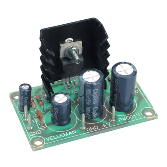
- Page 1 Total solder points: 33 Difficulty level: beginner 1 advanced 7W mono amplifier K4001 ILLUSTRATED ASSEMBLY MANUAL H4001IP-1...
-
Page 3: Specifications
Features & Specifications Features: This small amplifier is constructed around the TDA2003 IC, capable of delivering 4Wrms at 4ohms. The IC is completely thermally and short-circuit protected. A conventional direct current can be connected as supply. Specifications : Music output power : 7W/4ohm RMS output power : 3.5W/4ohm or 2W/8ohm Total harmonic distortion : 0.05% (1W/1KHz) Frequency response : 20Hz-20KHz (-3dB) -
Page 4: Assembly Hints
Assembly hints 1. Assembly (Skipping this can lead to troubles ! ) Ok, so we have your attention. These hints will help you to make this project successful. Read them carefully. 1.1 Make sure you have the right tools: • A good quality soldering iron (25-40W) with a small tip. - Page 5 AXIAL COMPONENTS ARE TAPED IN THE CORRECT MOUNTING SEQUENCE ! REMOVE THEM FROM THE TAPE ONE AT A TIME ! You will find the colour code for the resistances and the LEDs in the HALG (general manual) and on our website: http://www.velleman.be/common/service.aspx...
- Page 6 Construction 6. IC. 1. Resistors. 4. PCB tabs R... IC1 : TDA2003! R1 : 470 (4 - 7 - 1 - B) R2 : 4,7 (4 - 7 - B - B) R3 : 100 (1 - 0 - 1 - B) 5.
-
Page 7: Supply Connection
Supply connection 7. Supply connection Figure 1 is an example of a suitable mains supply for this circuit. Naturally, you can also use batteries to power the circuit. FUSEHOLDER MAINS FUSE 1A T POWER SWITCH 240V 3A RECTIFIER BRIDGE 1.5A 50V TRANSFORMER 12V AC 6VA STRAIN RELIEF... -
Page 8: Volume Control
Volume control 8. Volume control Adjust the volume by connecting a 47K logarithmic potentiometer as indicated in figure 2.0. TO AMPLIFIER SHIELDED CABLE Signal IN FROM SOURCE POTENTIOMETER 47K OHM LOG Fig. 2.0 SIGNAL (+) - Page 9 Connection example 9. Connection example Figure 3.0 is an example of a connection diagram of a 4 or 8 ohm speaker that is connected to the pins LS and GND. The input signal should be connected with the IN and GND pins. FROM AUDIO SOURCE 4/8 OHM SPEAKER 47K LOG POTENTIOMETER...
- Page 10 10. PCB layout.
- Page 11 Diagram 11. Diagram...
- Page 12 VELLEMAN Components NV Legen Heirweg 33 9890 Gavere Belgium Europe www.velleman.be www.velleman-kit.com Modifications and typographical errors reserved © Velleman Components nv. H4001IP - 2004 - ED1 5 4 1 0 3 2 9 2 8 9 0 0 3...
Need help?
Do you have a question about the K4001 and is the answer not in the manual?
Questions and answers