
Related Manuals for Velleman K4003


Summary of Contents for Velleman K4003
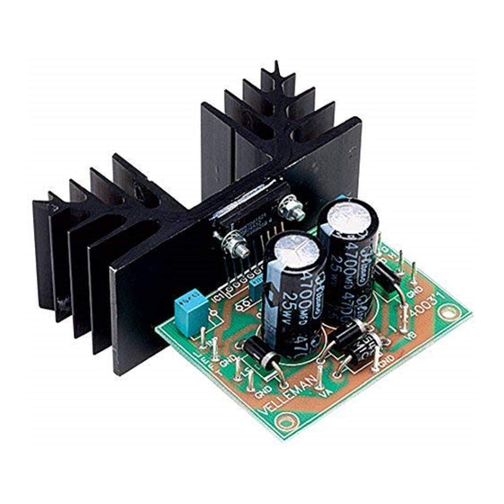
- Page 1 Total solder points: 46 Difficulty level: beginner 1 advanced 2 X 30W STEREO AMPLIFIER K4003 ILLUSTRATED ASSEMBLY MANUAL H4003IP-1...
- Page 2 VELLEMAN NV Legen Heirweg 33 9890 Gavere Belgium Europe www.velleman.be www.velleman-kit.com...
-
Page 3: Features And Specifications
Features & Specifications Features: This small amplifier is constructed with the TDA2616 IC, with a maximum supply capability of 2 x 15Wrms (4ohm) of 2 x 10Wrms (8ohm). The IC is thermally and short-circuit protected. Additional rectifier and smoothing filter are unnecessary, as alternating current can be directly connected to the unit. Specifications : Music power output: 2 x 30W / 4ohm RMS output: 2 x 15Wrms / 4ohm or 2 x 10Wrms / 8ohm... -
Page 4: Assembly Hints
Assembly hints 1. Assembly (Skipping this can lead to troubles ! ) Ok, so we have your attention. These hints will help you to make this project successful. Read them carefully. 1.1 Make sure you have the right tools: • A good quality soldering iron (25-40W) with a small tip. - Page 5 Assembly hints 1.3 Soldering Hints : 1- Mount the component against the PCB surface and carefully solder the leads 2- Make sure the solder joints are cone-shaped and shiny 3- Trim excess leads as close as possible to the solder joint REMOVE THEM FROM THE TAPE ONE AT A TIME ! DO NOT BLINDLY FOLLOW THE ORDER OF THE COMPONENTS ONTO THE TAPE.
- Page 6 Construction 6. Electrolytic Capacitors. 1. Resistors 4. PCB tabs Watch the polarity ! R... Left C6 : 2200µF C7 : 2200µF C... Right R1 : 8,2 (8 - 2 - B - B) R2 : 8,2 (8 - 2 - B - B) (2x) GND (2x) 2.
- Page 7 Construction 7. IC IC1 : TDA2616 Mount the IC with the metal back pointing at the edge of the circuit board. Mount it sufficiently high, so that the pins do NOT need to be pruned. Then mount the IC against the heatsink, as indicated in the diagram 1.0.
- Page 8 Connection 8. Connection Make the connections as indicated in figure 2.0 & fig 3.0. Watch the polarity of the loudspeakers. If a ring-core transformer is used, it is possible that the OV (GND) connection consists of two leads. Finish all connec- tions before switching on the power.
- Page 9 Fig. 3.0...
- Page 10 9. PCB layout.
- Page 11 Diagram 10. Diagram...
- Page 12 Modifications and typographical errors reserved VELLEMAN NV © Velleman nv. Legen Heirweg 33, 9890 Gavere H4003IP - 2004 - ED1 (rev.1) Belgium - Europe 5 4 1 0 3 2 9 2 8 9 0 3 4...
Need help?
Do you have a question about the K4003 and is the answer not in the manual?
Questions and answers