Velleman K4040 Manual
Hide thumbs
Also See for K4040:
- Illustrated assembly manual (28 pages) ,
- Illustrated assembly manual (28 pages)
Table of Contents
Advertisement
Quick Links
Total solder points: 700
Difficulty level:
beginner 1o 2o 3o 4o 5þ advanced
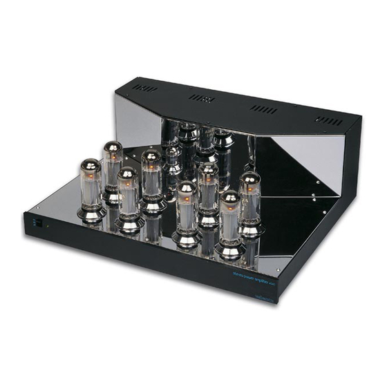
K4040
STEREO VALVE POWER AMPLIFIER
⇒ Pure valve sound with high quality EL34 valves
⇒ High quality black and chrome housing
⇒ Chrome valve socket covers
⇒ Easy bias adjustment with LED indication
⇒ Removable bottom for easy access and service
⇒ High quality capacitors and components
⇒ Gold plated input and speaker terminals
⇒ Standby function
⇒ Soft start circuit for power transformer
Specifications
• 2 x 90Wrms in 4 or 8Ω
• Up to 2 x 15Wrms full class A
• Bandwidth: 8Hz to 80KHz (-3dB/1W)
• Harmonic distortion: 0.1% @ 1W/1KHz
• Signal to noise ratio: >105dB (A weighted)
• Input sensitivity: 1Vrms
• 115VAC or 230VAC / 500VA max.
modifications reserved
ILLUSTRATED PARTLIST
H4040IP-ED1
Advertisement
Table of Contents

Related Manuals for Velleman K4040


Summary of Contents for Velleman K4040
- Page 1 Total solder points: 700 Difficulty level: beginner 1o 2o 3o 4o 5þ advanced K4040 STEREO VALVE POWER AMPLIFIER ⇒ Pure valve sound with high quality EL34 valves ⇒ High quality black and chrome housing ⇒ Chrome valve socket covers ⇒ Easy bias adjustment with LED indication ⇒...
- Page 2 COLOR= 2… 5 4K7= ( 4 - 7 - 2 - B ) 4K7= ( 4 - 7 - 0 - 1 - 1 ) COLOUR CODIFI- KLEUR CODICE CODIGO CODIGO VÄRI FÄRG FARVE FARGE FARB CODE CATION KODE SCHEMA COLORE KOODI KODE...
- Page 3 __________________________________________________________________________________________________________________________________________________________ VELLEMAN KIT NV Legen Heirweg 33 9890 Gavere Belgium http://www.velleman.be...
- Page 4 _______________________________________________________________________________________________________________________________________________________ STEREO VALVE AMPLIFIER TECHNICAL DATA* • Output power: 2 X 0 to 15 Wrms class A 2 x 15 to 90 Wrms class AB • Output impedance 4 or 8 Ohms • Ultra linear output transformers • Switch-on delay, to protect the output tubes: approx. 1 minute •...
- Page 5 __________________________________________________________________________________________________________________________________________________________ Assembly of the small input PCB P4040i: This PCB is used to connect the input signal (via two RCA sockets) via two holes at the rear of the cabi- net. 1. CAPACITORS 3. SHIELDED WIRE CONNECTION Carefully strip the screened cable supplied and make the connection as shown in the figure C...
- Page 6 _______________________________________________________________________________________________________________________________________________________ Assembly of the main PCB P4040B: Foreword: Because of the PCB dimensions, first mount the 8 large tube sockets so that the PCB can rest on a ta- ble, without the component leads being touched. When mounting the components, it is best to fold back the component leads a little before turning the PCB over to solder them.
- Page 7 __________________________________________________________________________________________________________________________________________________________ 2. JUMPERS 3. JUMPERS FOR VOLTAGE SELECTION Note that from J1 to J6, two jumper leads have to be mounted in the same hole. In order to get nice straight wiring, without too much folding and measuring, follow these hints: •...
- Page 8 _______________________________________________________________________________________________________________________________________________________ 5. ZENER DIODES (Check the polarity!) D... CATHODE ZD... CATHODE D1: 1N4148 D2 :1N4148 ZD1: 3V9 D3: 1N4007 ZD2: 3V9 D4: 1N4007 D5: 1N4007 6. ¼W RESISTORS D6: 1N4007 D7: 1N4007 D8: 1N4007 D9: 1N4007 D10: 1N4007 R... D11: 1N5408 not on tape ! D12: 1N5408 not on tape ! D13: 1N5408 not on tape ! D14: 1N5408 not on tape !
- Page 9 __________________________________________________________________________________________________________________________________________________________ R23: 820K (8 - 2 - 4 - B) 7. 1/2W RESISTORS R24: 820 (8 - 2 - 1 - B) R25: 180 (1 - 8 - 1 - B) R26: 1M (1 - 0 - 5 - B) R27: 22K (2 - 2 - 3 - B) R...
- Page 10 _______________________________________________________________________________________________________________________________________________________ 8. 1W RESISTORS 9. LEDs (Check the polarity!) R... COLOR = 2...5 LD... CATHODE R77: 270 (2 - 7 - 1 - B) LD1: 5mm red blinking R78: 10K (1 - 0 - 3 - B) LD2: 3mm bicolor: R79: 10K (1 - 0 - 3 - B) Carefully check the assembly of this LED: R80: 15K (1 - 5 - 3 - B)
- Page 11 __________________________________________________________________________________________________________________________________________________________ 10. IC SOCKETS 12. RESISTOR TRIMMERS, (Check the position of the notch!) vertical type IC... RV... IC1: 18P 11. REED RELAYS (Check the position of the notch!) RV1: 100K RV2: 100K RV3: 100K RV4: 100K RV5: 100K RV6: 100K PIN 1 RV7: 100K RV8: 100K...
- Page 12 _______________________________________________________________________________________________________________________________________________________ 14. 5W RESISTORS 16. CAPACITORS R... C... Check the minimum voltage ! C3: 100p/400V C4: 100p/400V REMARK: You will have two 8.2 Ohm 5W resis- C5: 22n/630V (0.022) tors left over for later use. R105: 15 C6: 22n/630V (0.022) R106: 15 C7: 470n (0.47, 474) R107: 15...
- Page 13 __________________________________________________________________________________________________________________________________________________________ 17. ELECTROLYTIC CAPACITOR 18. PCB CONNECTOR (Check the polarity!) C... With the holes facing the PCB edge ! SK3: 2 POLE SK4: 2 POLE SK5: 3 POLE SK6: 8 POLE C23: 4u7 SK7: 8 POLE C24: 100u SK8: 8 POLE C25: 470u C26: 470u 19.
- Page 14 _______________________________________________________________________________________________________________________________________________________ 20. POWER RELAYS 21. FUSE HOLDER The various relays have leads that correspond to the printing on the PCB: RY3: VR5V122C F... RY... RY4: VR10V121C Insert a 5A fuse for 115V RY5: VR10V121C Insert a 2.5A fuse for 230V Fit the protective cap to the fuse holder.
- Page 15 __________________________________________________________________________________________________________________________________________________________ 23. ELECTROLYTIC CAPACITOR 24. SWITCH (Check the polarity!) Generally these capacitors are from the snap-in type and cannot be mounted incorrectly. SW... IMPORTANT: C... Don't leave a gap between the SWITCH and the PCB! C35: 22u/350V C36: 22u/350V C37: 100u/400V SIDE VIEW C38: 100u/400V C39: 220u/450V...
- Page 16 _______________________________________________________________________________________________________________________________________________________ 26 6.3V VALVE WIRING Wiring for the 8 tube sockets V1 to V8. Use twisted brown wire for each one. For safety, it is advisable to check with an ohmmeter that the two 6.3V terminals are not short circuited. 6.3VAC 6.3VAC VIEWED FROM SOLDERSIDE...
- Page 17 __________________________________________________________________________________________________________________________________________________________ • Mount the input PCB on the right-hand side of the housing as shown in the figure. It is possible that a masking sticker from the cabinet will have to be removed, so that one of FIG 2 the supporting bushes can make contact with the cabinet. M3 NUT M3 LOCK WASHER 5mm SPACER...
- Page 18 _______________________________________________________________________________________________________________________________________________________ • Solder a 12 cm length of blue wire to the N terminal of the mains connector. • Solder a 12 cm length of brown wire to the L terminal of the mains connector. • Solder a 20 cm length of yellow/green earth wire and a 12 cm length to the middle terminal of the mains connector.
- Page 19 __________________________________________________________________________________________________________________________________________________________ WIRES WIRES ADHESIVE ADHESIVE ADHESIVE PROTECTION PROTECTION PROTECTION FOIL FOIL FOIL POWER OUTPUT OUTPUT TRANSFORMER TRANSFORMER TRANSFORMER 8D002 ZD043 ZD043 ADHESIVE ADHESIVE ADHESIVE FOOT FOOT FOOT WIRES WIRES WIRES FIG 6 ◊ Turn over the housing and solder the transformer leads to the output terminals, see figure. BLUE HEAT-SHRINK SLEEVE...
- Page 20 _______________________________________________________________________________________________________________________________________________________ ◊ Mount the supply transformer in the middle of the cabinet. Ensure that the leads are positioned as shown in the figure 6. The thick grey and green wires must be at the highest point. ◊ Mount an output transformer along the right-hand side of the housing, see figure 6. Check the po- sition of the wires.
- Page 21 __________________________________________________________________________________________________________________________________________________________ 8 0 4 MAINS OUTPUT TRANSFORMER POWER TRANSFORMER OUTPUT TRANSFORMER ZD043 8D002 ZD043 EARTH N BLUE L BROWN 6.3VAC 6.3VAC GREEN GRAY The thick grey wires may be twisted and connected the 6.3V connection (SK3) of the left-hand amplifier. The thick green wires should be connected in the same way to the 6.3V connection of the right-hand amplifier PCB.
- Page 22 _______________________________________________________________________________________________________________________________________________________ FIRST SWITCH OFF THE MAINS VOLTAGE AND REMOVE THE MAINS CORD FROM THE SOCKET. WAIT FOR A COUPLE OF MINUTES UNTIL THE HIGH VOLTAGES ON THE SUPPLY ELCOS HAVE DISSAPEARED. Fit the small tubes: V9 and V10, type ECC83 or 12AX7, CV492. V11, type ECC82 or 12AU7, CV491.
- Page 23 __________________________________________________________________________________________________________________________________________________________ Adjustment of the right-hand channel: ◊ Ensure that all switches of the left-hand channel are OFF (up). ◊ Switch the first switch of SW3 (right DIP switch) ON (down). ◊ Carefully adjust RV5 until the second or third LED lights up (LD4 or LD5). Switch OFF the first switch (up).
- Page 24 _______________________________________________________________________________________________________________________________________________________ FINAL ASSEMBLY OF THE CABINET Before fitting the covers, check the supply and amplifier PCBs to see that no components have been mounted too high. ◊ Mount the cover on the base (set the cabinet on its side) using black Allen bolts. ◊...
- Page 25 If you decide to send the complete unit, you MUST order a special protective shipping box (order code DM4040) from you distributor. If not then the unit will surely be damaged during transport and it will suffer damage beyond repair. Velleman Kit can never be hold responsible for damage during transport! Happy listening.
- Page 26 _______________________________________________________________________________________________________________________________________________________...
- Page 27 __________________________________________________________________________________________________________________________________________________________...
- Page 28 _______________________________________________________________________________________________________________________________________________________...
- Page 29 __________________________________________________________________________________________________________________________________________________________...
Need help?
Do you have a question about the K4040 and is the answer not in the manual?
Questions and answers